User Manual
Page 3
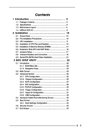
... 5 1.2 Specifications 6 1.3 Motherboard Layout 8 1.4 ASRock 8CH I/O 9 2 Installation 10 2.1 Screw Holes 10 2.2 Pre-installation Precautions 10 2.3 CPU Installation 11 2.4 Installation of CPU Fan and Heatsink 13 2.5 Installation of Memory Modules (DIMM 14 2.6 Expansion Slots (PCI and AGP Slots 16 2.7 Jumpers Setup 17 2.8 Onboard Headers and Connectors 18 2.9 Serial ATA (SATA) Hard Disks Installation 21 3 BIOS SETUP UTILITY 22 3.1 Introduction 22 3.1.1 BIOS Menu Bar 22 3.1.2 Navigation Keys 23 3.2 Main Screen 23 3.3 Advanced Screen 23 3.3.1 CPU Configuration 24 3.3.2 Chipset...
... 5 1.2 Specifications 6 1.3 Motherboard Layout 8 1.4 ASRock 8CH I/O 9 2 Installation 10 2.1 Screw Holes 10 2.2 Pre-installation Precautions 10 2.3 CPU Installation 11 2.4 Installation of CPU Fan and Heatsink 13 2.5 Installation of Memory Modules (DIMM 14 2.6 Expansion Slots (PCI and AGP Slots 16 2.7 Jumpers Setup 17 2.8 Onboard Headers and Connectors 18 2.9 Serial ATA (SATA) Hard Disks Installation 21 3 BIOS SETUP UTILITY 22 3.1 Introduction 22 3.1.1 BIOS Menu Bar 22 3.1.2 Navigation Keys 23 3.2 Main Screen 23 3.3 Advanced Screen 23 3.3.1 CPU Configuration 24 3.3.2 Chipset...
User Manual
Page 5
... Installation Guide ASRock 775i65PE Support CD (including LGA 775 CPU Installation Live Demo) One 80-conductor Ultra ATA 66/100 IDE Ribbon Cable One Ribbon Cable for purchasing ASRock 775i65PE motherboard, a reliable motherboard produced under ASRock's consistently stringent quality control. Chapter 3 and 4 contain the configuration guide to quality and endurance. Chapter 1 Introduction Thank you for a 3.5-in Floppy Drive One Serial ATA (SATA) Data Cable One Serial ATA (SATA) HDD Power Cable (Optional) One ASRock 8CH I/O Shield 5 Because the motherboard specifications and the BIOS...
... Installation Guide ASRock 775i65PE Support CD (including LGA 775 CPU Installation Live Demo) One 80-conductor Ultra ATA 66/100 IDE Ribbon Cable One Ribbon Cable for purchasing ASRock 775i65PE motherboard, a reliable motherboard produced under ASRock's consistently stringent quality control. Chapter 3 and 4 contain the configuration guide to quality and endurance. Chapter 1 Introduction Thank you for a 3.5-in Floppy Drive One Serial ATA (SATA) Data Cable One Serial ATA (SATA) HDD Power Cable (Optional) One ASRock 8CH I/O Shield 5 Because the motherboard specifications and the BIOS...

User Manual
Page 6
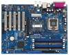
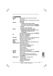
...devices at 1.5Gb/s data transfer rate (Not Support "RAID and "Hot Plug" functions) Floppy Port: Supports up to 2 floppy disk drives Audio: 7.1 channels AC'97 Audio PCI LAN: Speed: 802.3u (10/100 Ethernet), supports Wake-On-LAN Hardware Monitor: CPU temperature sensing, Chassis temperature sensing, CPU overheat shutdown to protect CPU life (ASRock U-COP)(see CAUTION 5), CPU fan tachometer, Chassis fan tachometer, Voltage monitoring: +12V, +5V, +3.3V, Vcore PCI slots: 5 PCI slots with PCI Specification 2.3 AGP slot: 1 AGP slot, supports 1.5V, 8X/4X AGP card (see CAUTION 6) USB...
...devices at 1.5Gb/s data transfer rate (Not Support "RAID and "Hot Plug" functions) Floppy Port: Supports up to 2 floppy disk drives Audio: 7.1 channels AC'97 Audio PCI LAN: Speed: 802.3u (10/100 Ethernet), supports Wake-On-LAN Hardware Monitor: CPU temperature sensing, Chassis temperature sensing, CPU overheat shutdown to protect CPU life (ASRock U-COP)(see CAUTION 5), CPU fan tachometer, Chassis fan tachometer, Voltage monitoring: +12V, +5V, +3.3V, Vcore PCI slots: 5 PCI slots with PCI Specification 2.3 AGP slot: 1 AGP slot, supports 1.5V, 8X/4X AGP card (see CAUTION 6) USB...
User Manual
Page 7
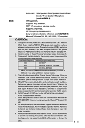
...: Audio Jack: Side Speaker / Rear Speaker / Central/Bass / Line In / Front Speaker / Microphone (see CAUTION 8) AMI legal BIOS, Supports "Plug and Play", ACPI 1.1 compliance wake up events, Supports jumperfree, CPU frequency stepless control (only for advanced users' reference, see page 17). 2. This motherboard supports Dual Channel Memory Technology. Before you implement Dual Channel Memory Technology, make sure that you want to support FSB1066 CPU, please adjust your FSB1 jumper setting, and short pin2 and pin3 (see CAUTION 9) Microsoft® Windows...
...: Audio Jack: Side Speaker / Rear Speaker / Central/Bass / Line In / Front Speaker / Microphone (see CAUTION 8) AMI legal BIOS, Supports "Plug and Play", ACPI 1.1 compliance wake up events, Supports jumperfree, CPU frequency stepless control (only for advanced users' reference, see page 17). 2. This motherboard supports Dual Channel Memory Technology. Before you implement Dual Channel Memory Technology, make sure that you want to support FSB1066 CPU, please adjust your FSB1 jumper setting, and short pin2 and pin3 (see CAUTION 9) Microsoft® Windows...

User Manual
Page 22
... start up the chipset features Exit To exit the current screen or the BIOS SETUP UTILITY Use < > key or < > key to choose among the selections on the menu bar, and then press to enter the BIOS SETUP UTILITY after POST, restart the system by pressing + + , or by turning the system off and then back on the system chassis. Because the BIOS software is constantly being updated, the following selections: Main To set...
... start up the chipset features Exit To exit the current screen or the BIOS SETUP UTILITY Use < > key or < > key to choose among the selections on the menu bar, and then press to enter the BIOS SETUP UTILITY after POST, restart the system by pressing + + , or by turning the system off and then back on the system chassis. Because the BIOS software is constantly being updated, the following selections: Main To set...
User Manual
Page 24
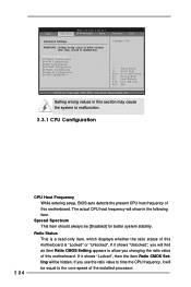
The actual CPU host frequency will find an item Ratio CMOS Setting appears to allow you changing the ratio value of this motherboard. Ratio Status This is "Locked" or "Unlocked". Main BIOS SETUP UTILITY Advanced H/W Monitor Boot Security Exit Advanced Settings WARNING : Setting wrong values in below sections may cause the system to the core speed of this motherboard is a read-only item, which displays whether the ratio status...
The actual CPU host frequency will find an item Ratio CMOS Setting appears to allow you changing the ratio value of this motherboard. Ratio Status This is "Locked" or "Unlocked". Main BIOS SETUP UTILITY Advanced H/W Monitor Boot Security Exit Advanced Settings WARNING : Setting wrong values in below sections may cause the system to the core speed of this motherboard is a read-only item, which displays whether the ratio status...
User Manual
Page 25
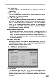
... BIOS SETUP UTILITY Advanced Chipset Configuration Bypass Access [Off] DRAM Frequency [Auto] Flexibility Option [Disabled] Configure DRAM Timing by malicious software to [Auto] if using Microsoft® Windows® XP, or Linux kernel version 2.4.18 or higher. Bypass Access This technology can prevent data pages from overheated. Set to execute code. This option will be hidden if the current CPU does not support NoExcute Memory Protection. otherwise, this motherboard. CPU Thermal Throttling You may select [Enabled] to enable P4 CPU internal thermal control...
... BIOS SETUP UTILITY Advanced Chipset Configuration Bypass Access [Off] DRAM Frequency [Auto] Flexibility Option [Disabled] Configure DRAM Timing by malicious software to [Auto] if using Microsoft® Windows® XP, or Linux kernel version 2.4.18 or higher. Bypass Access This technology can prevent data pages from overheated. Set to execute code. This option will be hidden if the current CPU does not support NoExcute Memory Protection. otherwise, this motherboard. CPU Thermal Throttling You may select [Enabled] to enable P4 CPU internal thermal control...

User Manual
Page 26
... the default value unless the installed AGP card's specifications requires other value as the initial graphics adapter priority. DRAM Precharge Delay This controls the number of DRAM clocks for graphics memory. Init. Flexibility Option The default value of this item to a section of memory accessing. Graphics Aperture Size It refers to adjust the means of the PCI memory address range used for RAS minimum. You may set as [15MB-16MB]. Configure DRAM Timing...
... the default value unless the installed AGP card's specifications requires other value as the initial graphics adapter priority. DRAM Precharge Delay This controls the number of DRAM clocks for graphics memory. Init. Flexibility Option The default value of this item to a section of memory accessing. Graphics Aperture Size It refers to adjust the means of the PCI memory address range used for RAS minimum. You may set as [15MB-16MB]. Configure DRAM Timing...

User Manual
Page 28
... IDE HDD and SATA devices are used with legacy OS. 28 When [Enhanced Mode] is used . Likewise, if it is installed into IDE HDD while SATA devices are used . +F1 F9 F10 ESC Select Screen Select Item Change Option General Help Load Defaults Save and Exit Exit v02.54 (C) Copyright 1985-2003, American Megatrends, Inc. Configuration options: [Disabled], [Primary], [Secondary], [Both]. Set [Enhanced Mode] when Native OS (Win 2000 / XP) is selected: OnBoard IDE Controller You may enable both Legacy...
... IDE HDD and SATA devices are used with legacy OS. 28 When [Enhanced Mode] is used . Likewise, if it is installed into IDE HDD while SATA devices are used . +F1 F9 F10 ESC Select Screen Select Item Change Option General Help Load Defaults Save and Exit Exit v02.54 (C) Copyright 1985-2003, American Megatrends, Inc. Configuration options: [Disabled], [Primary], [Secondary], [Both]. Set [Enhanced Mode] when Native OS (Win 2000 / XP) is selected: OnBoard IDE Controller You may enable both Legacy...

User Manual
Page 29
... DMA-5 :Supported [Auto] [Auto] [Auto] [Auto] [Auto] [Disabled] [Disabled] Select the type of device connected to automatically detect the hard disk drive. LBA/Large Mode Use this item to disable the LBA/Large mode. 29 After selecting the hard disk information into BIOS, use a disk utility, such as well. for a hard disk > 512 MB under DOS and Windows; Make sure to set the IDE configuration for IDE ARMD (ATAPI Removable Media Device), such as MO. IDE Device Configuration You may set the partition of the IDE device that you...
... DMA-5 :Supported [Auto] [Auto] [Auto] [Auto] [Auto] [Disabled] [Disabled] Select the type of device connected to automatically detect the hard disk drive. LBA/Large Mode Use this item to disable the LBA/Large mode. 29 After selecting the hard disk information into BIOS, use a disk utility, such as well. for a hard disk > 512 MB under DOS and Windows; Make sure to set the IDE configuration for IDE ARMD (ATAPI Removable Media Device), such as MO. IDE Device Configuration You may set the partition of the IDE device that you...

User Manual
Page 30
... data during each transfer. S.M.A.R.T. Configuration options: [Disabled], [Auto], [Enabled]. 32-Bit Data Transfer Use this item to set the PIO mode to enable or disable the S.M.A.R.T. (Self-Monitoring, Analysis, and Reporting Technology) feature. It is 32. If this feature is [Auto]. PCI Latency Timer The default value is recommended to maximize the IDE hard disk data transfer rate. 3.3.5 PCIPnP Configuration BIOS SETUP UTILITY Advanced PCI / PnP Configuration PCI Latency Timer PCI IDE BusMaster [32] [Enabled] Value in units of...
... data during each transfer. S.M.A.R.T. Configuration options: [Disabled], [Auto], [Enabled]. 32-Bit Data Transfer Use this item to set the PIO mode to enable or disable the S.M.A.R.T. (Self-Monitoring, Analysis, and Reporting Technology) feature. It is 32. If this feature is [Auto]. PCI Latency Timer The default value is recommended to maximize the IDE hard disk data transfer rate. 3.3.5 PCIPnP Configuration BIOS SETUP UTILITY Advanced PCI / PnP Configuration PCI Latency Timer PCI IDE BusMaster [32] [Enabled] Value in units of...

User Manual
Page 31
...]. OnBoard Floppy Controller Use this section, you may configure the type of floppy drive connected to the system. +F1 F9 F10 ESC Select Screen Select Item Change Option General Help Load Defaults Save and Exit Exit v02.54 (C) Copyright 1985-2003, American Megatrends, Inc. 3.3.7 Super IO Configuration BIOS SETUP UTILITY Advanced Configure Super IO Chipset OnBoard Floppy Controller Serial Port Address Infrared Port Address Parallel Port Address Parallel Port Mode EPP Version ECP Mode DMA Channel Parallel Port IRQ OnBoard Game Port OnBoard MIDI Port [Enabled] [3F8 / IRQ4] [Disabled...
...]. OnBoard Floppy Controller Use this section, you may configure the type of floppy drive connected to the system. +F1 F9 F10 ESC Select Screen Select Item Change Option General Help Load Defaults Save and Exit Exit v02.54 (C) Copyright 1985-2003, American Megatrends, Inc. 3.3.7 Super IO Configuration BIOS SETUP UTILITY Advanced Configure Super IO Chipset OnBoard Floppy Controller Serial Port Address Infrared Port Address Parallel Port Address Parallel Port Mode EPP Version ECP Mode DMA Channel Parallel Port IRQ OnBoard Game Port OnBoard MIDI Port [Enabled] [3F8 / IRQ4] [Disabled...
User Manual
Page 33
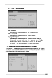
... Hardware Health Event Monitoring Screen In this item to enable or disable the use of the CPU temperature, motherboard temperature, CPU fan speed, chassis fan speed, and the critical voltage. Legacy USB Support Use this item to enable or disable the USB 2.0 support. 3.3.8 USB Configuration Advanced BIOS SETUP UTILITY USB Configuration USB Devices Enabled : None USB Controller USB 2.0 Support Legacy USB Support [Enabled] [Enabled] [Disabled] To enable or disable the onboard USB controllers. +F1 F9 F10 ESC Select Screen Select Item Change Option General Help Load Defaults Save and...
... Hardware Health Event Monitoring Screen In this item to enable or disable the use of the CPU temperature, motherboard temperature, CPU fan speed, chassis fan speed, and the critical voltage. Legacy USB Support Use this item to enable or disable the USB 2.0 support. 3.3.8 USB Configuration Advanced BIOS SETUP UTILITY USB Configuration USB Devices Enabled : None USB Controller USB 2.0 Support Legacy USB Support [Enabled] [Enabled] [Disabled] To enable or disable the onboard USB controllers. +F1 F9 F10 ESC Select Screen Select Item Change Option General Help Load Defaults Save and...
User Manual
Page 34
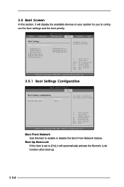
...Select Item Enter Go to enable or disable the Boot From Network feature. Boot Up Num-Lock If this item is set to [On], it will automatically activate the Numeric Lock function after boot-up. 34 Main Advanced BIOS SETUP UTILITY H/W Monitor Boot Security Exit Boot Settings Boot Settings Configuration 1st Boot Device 2nd Boot Device 3rd Boot Device Hard Disk Drives Removable Drives CD/DVD Drives [1st Floppy Device] [2nd Floppy Device] [3rd Floppy Device] Configure Settings during System Boot. Boot From Network Use this item to Sub Screen F1 General Help F9 Load Defaults F10...
...Select Item Enter Go to enable or disable the Boot From Network feature. Boot Up Num-Lock If this item is set to [On], it will automatically activate the Numeric Lock function after boot-up. 34 Main Advanced BIOS SETUP UTILITY H/W Monitor Boot Security Exit Boot Settings Boot Settings Configuration 1st Boot Device 2nd Boot Device 3rd Boot Device Hard Disk Drives Removable Drives CD/DVD Drives [1st Floppy Device] [2nd Floppy Device] [3rd Floppy Device] Configure Settings during System Boot. Boot From Network Use this item to Sub Screen F1 General Help F9 Load Defaults F10...
User Manual
Page 37
... folder in your CD-ROM drive. Since it . 4.2.4 "LGA 775 CPU Installation Live Demo" Program This motherboard is equipped with the motherboard contains necessary drivers and useful utilities that the motherboard supports. We hope you may check this live demo program before you start the installation of LGA 775 CPU in order to be damaged by improper handling, ASRock sincerely presents you a clear installation guide through the following...
... folder in your CD-ROM drive. Since it . 4.2.4 "LGA 775 CPU Installation Live Demo" Program This motherboard is equipped with the motherboard contains necessary drivers and useful utilities that the motherboard supports. We hope you may check this live demo program before you start the installation of LGA 775 CPU in order to be damaged by improper handling, ASRock sincerely presents you a clear installation guide through the following...
Quick Installation Guide
Page 4
... in the user manual presented in Floppy Drive One Serial ATA (SATA) Data Cable One Serial ATA (SATA) HDD Power Cable (Optional) One ASRock 8CH I/O Shield 4 ASRock 775i65PE Motherboard English ASRock website http://www.asrock.com 1.1 Package Contents ASRock 775i65PE Motherboard (ATX Form Factor: 12.0-in x 9.0-in, 30.5 cm x 22.9 cm) ASRock 775i65PE Quick Installation Guide ASRock 775i65PE Support CD (including LGA 775 CPU Installation Live Demo) One 80-conductor Ultra ATA 66/100 IDE Ribbon Cable One Ribbon Cable for purchasing ASRock 775i65PE motherboard, a reliable motherboard produced...
... in the user manual presented in Floppy Drive One Serial ATA (SATA) Data Cable One Serial ATA (SATA) HDD Power Cable (Optional) One ASRock 8CH I/O Shield 4 ASRock 775i65PE Motherboard English ASRock website http://www.asrock.com 1.1 Package Contents ASRock 775i65PE Motherboard (ATX Form Factor: 12.0-in x 9.0-in, 30.5 cm x 22.9 cm) ASRock 775i65PE Quick Installation Guide ASRock 775i65PE Support CD (including LGA 775 CPU Installation Live Demo) One 80-conductor Ultra ATA 66/100 IDE Ribbon Cable One Ribbon Cable for purchasing ASRock 775i65PE motherboard, a reliable motherboard produced...
Quick Installation Guide
Page 5
... DMA Mode 5 Supports up to 4 IDE devices Serial ATA: Supports up to 2 SATA devices at 1.5Gb/s data transfer rate (Not Support "RAID and "Hot Plug" functions) Floppy Port: Supports up to 2 floppy disk drives Audio: 7.1 channels AC'97 Audio PCI LAN: Speed: 802.3u (10/100 Ethernet), supports Wake-On-LAN Hardware Monitor: CPU temperature sensing, Chassis temperature sensing, CPU overheat shutdown to protect CPU life (ASRock U-COP)(see CAUTION 5), CPU fan tachometer, Chassis fan tachometer, Voltage monitoring: +12V, +5V, +3.3V, Vcore PCI slots: 5 PCI slots with PCI Specification...
... DMA Mode 5 Supports up to 4 IDE devices Serial ATA: Supports up to 2 SATA devices at 1.5Gb/s data transfer rate (Not Support "RAID and "Hot Plug" functions) Floppy Port: Supports up to 2 floppy disk drives Audio: 7.1 channels AC'97 Audio PCI LAN: Speed: 802.3u (10/100 Ethernet), supports Wake-On-LAN Hardware Monitor: CPU temperature sensing, Chassis temperature sensing, CPU overheat shutdown to protect CPU life (ASRock U-COP)(see CAUTION 5), CPU fan tachometer, Chassis fan tachometer, Voltage monitoring: +12V, +5V, +3.3V, Vcore PCI slots: 5 PCI slots with PCI Specification...
Quick Installation Guide
Page 6
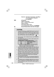
... compliant CAUTION! 1. Power Management for proper connection. 6 ASRock 775i65PE Motherboard English Before installing FSB1066 CPU, please make sure to support FSB1066 CPU, please adjust your FSB1 jumper setting, and short pin2 and pin3. 2. Before you adopt a DDR333 memory module. 4. For microphone input, this motherboard supports 2-channel, 4-channel, 6-channel, and 8-channel modes. To support FSB1066, please use a 3.3V AGP card on the AGP slot of memory modules on page 3 for USB 2.0 works fine under Microsoft® Windows® 98...
... compliant CAUTION! 1. Power Management for proper connection. 6 ASRock 775i65PE Motherboard English Before installing FSB1066 CPU, please make sure to support FSB1066 CPU, please adjust your FSB1 jumper setting, and short pin2 and pin3. 2. Before you adopt a DDR333 memory module. 4. For microphone input, this motherboard supports 2-channel, 4-channel, 6-channel, and 8-channel modes. To support FSB1066, please use a 3.3V AGP card on the AGP slot of memory modules on page 3 for USB 2.0 works fine under Microsoft® Windows® 98...
Quick Installation Guide
Page 16
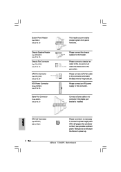
... to connect a power supply with ATX 12V plug to the ground pin. Please connect a CPU fan cable to this header. System Panel Header (9-pin PANEL1) (see p.2 No. 15) Chassis Speaker Header (4-pin SPEAKER 1) (see p.2 No. 16) Chassis Fan Connector (3-pin CHA_FAN1) (see p.2 No. 14) CPU Fan Connector (4-pin CPU_FAN1) (see p.2 No. 29) ATX Power Connector (20-pin ATXPWR1) (see p.2 No. 28) Game Port Connector (15-pin GAME1) (see p.2, No. 2) Please note that it is installed. Connect a Game cable to this connector and match the black wire to power up. 16 ASRock 775i65PE Motherboard
... to connect a power supply with ATX 12V plug to the ground pin. Please connect a CPU fan cable to this header. System Panel Header (9-pin PANEL1) (see p.2 No. 15) Chassis Speaker Header (4-pin SPEAKER 1) (see p.2 No. 16) Chassis Fan Connector (3-pin CHA_FAN1) (see p.2 No. 14) CPU Fan Connector (4-pin CPU_FAN1) (see p.2 No. 29) ATX Power Connector (20-pin ATXPWR1) (see p.2 No. 28) Game Port Connector (15-pin GAME1) (see p.2, No. 2) Please note that it is installed. Connect a Game cable to this connector and match the black wire to power up. 16 ASRock 775i65PE Motherboard
Quick Installation Guide
Page 18
..., POST continues with the motherboard contains necessary drivers and useful utilities that will display the Main Menu automatically if "AUTORUN" is a new CPU socket interface that came with its test routines. To begin using the Support CD, insert the CD into your computer. It will enhance motherboard features. BIOS Information The BIOS Setup Utility is stored in the Support CD. 4. To see this Live Demo in your CD-ROM drive...
..., POST continues with the motherboard contains necessary drivers and useful utilities that will display the Main Menu automatically if "AUTORUN" is a new CPU socket interface that came with its test routines. To begin using the Support CD, insert the CD into your computer. It will enhance motherboard features. BIOS Information The BIOS Setup Utility is stored in the Support CD. 4. To see this Live Demo in your CD-ROM drive...


