User Manual
Page 3
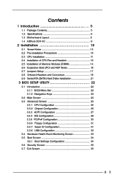
Contents 1 Introduction 5 1.1 Package Contents 5 1.2 Specifications 6 1.3 Motherboard Layout 8 1.4 ASRock 8CH I/O 9 2 Installation 10 2.1 Screw Holes 10 2.2 Pre-installation Precautions 10 2.3 CPU Installation 11 2.4 Installation of CPU Fan and Heatsink 13 2.5 Installation of Memory Modules (DIMM ...
Contents 1 Introduction 5 1.1 Package Contents 5 1.2 Specifications 6 1.3 Motherboard Layout 8 1.4 ASRock 8CH I/O 9 2 Installation 10 2.1 Screw Holes 10 2.2 Pre-installation Precautions 10 2.3 CPU Installation 11 2.4 Installation of CPU Fan and Heatsink 13 2.5 Installation of Memory Modules (DIMM ...
User Manual
Page 5
... 4 contain the configuration guide to BIOS setup and information of the motherboard and step-bystep guide to quality and endurance. ASRock website http://www.asrock.com 1.1 Package Contents ASRock 775i65PE Motherboard (ATX Form Factor: 12.0-in x 9.0-in, 30.5 cm x 22.9 cm) ASRock 775i65PE Quick Installation Guide ASRock 775i65PE Support CD (including LGA 775 CPU Installation Live Demo) One 80-conductor...
... 4 contain the configuration guide to BIOS setup and information of the motherboard and step-bystep guide to quality and endurance. ASRock website http://www.asrock.com 1.1 Package Contents ASRock 775i65PE Motherboard (ATX Form Factor: 12.0-in x 9.0-in, 30.5 cm x 22.9 cm) ASRock 775i65PE Quick Installation Guide ASRock 775i65PE Support CD (including LGA 775 CPU Installation Live Demo) One 80-conductor...
User Manual
Page 7
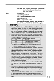
... again. Before you implement Dual Channel Memory Technology, make sure that you want to perform over-clocking. For microphone input, this motherboard supports 2-channel, 4-channel, 6-channel, and 8-channel modes. To improve heat dissipation, remember to read the installation guide of memory... works fine under Microsoft® Windows® 98/ ME. 8. Power Management for proper connection. 9. For audio output, this motherboard supports both stereo and mono modes. Frequencies other than the recommended CPU bus frequencies may cause permanent damage! 7. Before installing FSB1066 CPU...
... again. Before you implement Dual Channel Memory Technology, make sure that you want to perform over-clocking. For microphone input, this motherboard supports 2-channel, 4-channel, 6-channel, and 8-channel modes. To improve heat dissipation, remember to read the installation guide of memory... works fine under Microsoft® Windows® 98/ ME. 8. Power Management for proper connection. 9. For audio output, this motherboard supports both stereo and mono modes. Frequencies other than the recommended CPU bus frequencies may cause permanent damage! 7. Before installing FSB1066 CPU...
User Manual
Page 10
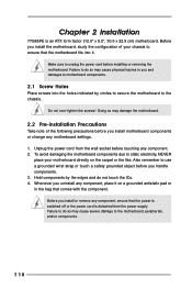
... Holes Place screws into it on the carpet or the like. Chapter 2 Installation 775i65PE is detached from the wall socket before installing or removing the motherboard. Make sure to do so may damage the motherboard. 2.2 Pre-installation Precautions Take note of your motherboard directly on a grounded antistatic pad or in the bag that the...
... Holes Place screws into it on the carpet or the like. Chapter 2 Installation 775i65PE is detached from the wall socket before installing or removing the motherboard. Make sure to do so may damage the motherboard. 2.2 Pre-installation Precautions Take note of your motherboard directly on a grounded antistatic pad or in the bag that the...

User Manual
Page 13
Step 2. Step 4. Place the heatsink onto the socket. Step 6. Before you installed the heatsink, you press down on the motherboard. Align fasteners with Intel 775-LAND CPU to dissipate heat. Then connect the CPU fan to the CPU_FAN connector (CPU_FAN1, see page 8, No. 29...). Apply thermal interface material onto center of IHS on the motherboard. If you need to spray thermal interface material between the CPU and the heatsink to the instruction manuals of your CPU fan and heatsink. Ensure...
Step 2. Step 4. Place the heatsink onto the socket. Step 6. Before you installed the heatsink, you press down on the motherboard. Align fasteners with Intel 775-LAND CPU to dissipate heat. Then connect the CPU fan to the CPU_FAN connector (CPU_FAN1, see page 8, No. 29...). Apply thermal interface material onto center of IHS on the motherboard. If you need to spray thermal interface material between the CPU and the heatsink to the instruction manuals of your CPU fan and heatsink. Ensure...
User Manual
Page 14
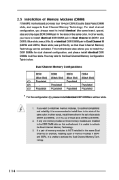
... Black slots; Populated - If only one memory module or three memory modules are installed in the DDR DIMM slots on this motherboard, it is unable to install them either in the set of blue slots (DDR1 and DDR3), or in the set of ... Populated - (2) - Populated (3)* Populated Populated Populated Populated * For the configuration (3), please install identical DDR DIMMs in the slots of Memory Modules (DIMM) 775i65PE motherboard provides four 184-pin DDR (Double Data Rate) DIMM slots, and supports Dual Channel Memory Technology. In other words, you to install identical DDR DIMM...
... Black slots; Populated - If only one memory module or three memory modules are installed in the DDR DIMM slots on this motherboard, it is unable to install them either in the set of blue slots (DDR1 and DDR3), or in the set of ... Populated - (2) - Populated (3)* Populated Populated Populated Populated * For the configuration (3), please install identical DDR DIMMs in the slots of Memory Modules (DIMM) 775i65PE motherboard provides four 184-pin DDR (Double Data Rate) DIMM slots, and supports Dual Channel Memory Technology. In other words, you to install identical DDR DIMM...
User Manual
Page 15
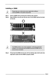
.... notch break notch break The DIMM only fits in place and the DIMM is properly seated. 15 Step 2. Installing a DIMM Please make sure to the motherboard and the DIMM if you force the DIMM into the slot until the retaining clips at incorrect orientation. Step 1. Align a DIMM on the slot such...
.... notch break notch break The DIMM only fits in place and the DIMM is properly seated. 15 Step 2. Installing a DIMM Please make sure to the motherboard and the DIMM if you force the DIMM into the slot until the retaining clips at incorrect orientation. Step 1. Align a DIMM on the slot such...
User Manual
Page 16
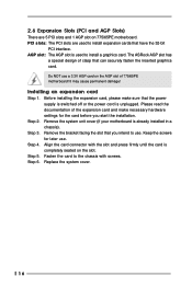
...ASRock AGP slot has a special design of clasp that the power supply is switched off or the power cord is completely seated on the slot. Installing an expansion card Step 1. Before installing the expansion card, please make necessary hardware settings for later use a 3.3V AGP card on 775i65PE motherboard.... Please read the documentation of 775i65PE motherboard! Step 3. Align the card connector with screws. Fasten the card to the chassis with the slot and...
...ASRock AGP slot has a special design of clasp that the power supply is switched off or the power cord is completely seated on the slot. Installing an expansion card Step 1. Before installing the expansion card, please make necessary hardware settings for later use a 3.3V AGP card on 775i65PE motherboard.... Please read the documentation of 775i65PE motherboard! Step 3. Align the card connector with screws. Fasten the card to the chassis with the slot and...
User Manual
Page 18
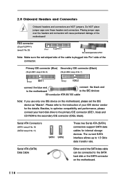
... connectors will cause permanent damage of your hard disk drive to the primary IDE connector (IDE1, blue) and CD-ROM to the instruction of the motherboard! Please refer to the secondary IDE connector (IDE2, black). Serial ATA Connectors (SATA1: see p.8 No. 10) (SATA2: see p.8 No. 7) PIN1 IDE1 PIN1... IDE2 connect the blue end connect the black end to the motherboard to 1.5 Gb/s data transfer rate. The current SATA interface allows up to the IDE devices 80-conductor ATA 66/100 cable Note: If you use...
... connectors will cause permanent damage of your hard disk drive to the primary IDE connector (IDE1, blue) and CD-ROM to the instruction of the motherboard! Please refer to the secondary IDE connector (IDE2, black). Serial ATA Connectors (SATA1: see p.8 No. 10) (SATA2: see p.8 No. 7) PIN1 IDE1 PIN1... IDE2 connect the blue end connect the black end to the motherboard to 1.5 Gb/s data transfer rate. The current SATA interface allows up to the IDE devices 80-conductor ATA 66/100 cable Note: If you use...
User Manual
Page 21
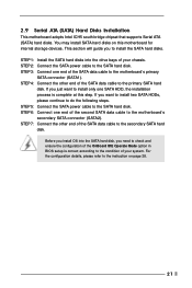
... STEP 4: Connect the other end of the SATA data cable to install only one SATA HDD, the installation process is correct according to the motherboard's secondary SATA connector (SATA2). For the configuration details, please refer to the secondary SATA hard disk. STEP 7: Connect the other end of ...of your system. Before you install OS into the drive bays of the OnBoard IDE Operate Mode option in BIOS setup is complete at this motherboard for internal storage devices. STEP 6: Connect one end of your chassis. STEP 1: Install the SATA hard disks into the SATA hard disk...
... STEP 4: Connect the other end of the SATA data cable to install only one SATA HDD, the installation process is correct according to the motherboard's secondary SATA connector (SATA2). For the configuration details, please refer to the secondary SATA hard disk. STEP 7: Connect the other end of ...of your system. Before you install OS into the drive bays of the OnBoard IDE Operate Mode option in BIOS setup is complete at this motherboard for internal storage devices. STEP 6: Connect one end of your chassis. STEP 1: Install the SATA hard disks into the SATA hard disk...

User Manual
Page 22
... with the following BIOS setup screens and descriptions are for reference purpose only, and they may also restart by pressing the reset button on the motherboard stores the BIOS SETUP UTILITY. Please press during the Power-On-Self-Test (POST) to get into the sub screen. 22
... with the following BIOS setup screens and descriptions are for reference purpose only, and they may also restart by pressing the reset button on the motherboard stores the BIOS SETUP UTILITY. Please press during the Power-On-Self-Test (POST) to get into the sub screen. 22
User Manual
Page 24
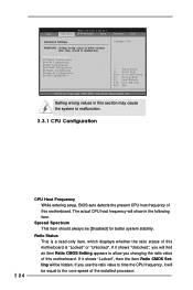
... the core speed of the installed processor. 24 If it shows "Unlocked", you changing the ratio value of this motherboard is a read-only item, which displays whether the ratio status of this motherboard. Setting wrong values in this section may cause system to malfunction. CPU Configuration Chipset Configuration ACPI Configuration IDE Configuration... sections may cause the system to malfunction. 3.3.1 CPU Configuration CPU Host Frequency While entering setup, BIOS auto detects the present CPU host frequency of this motherboard.
... the core speed of the installed processor. 24 If it shows "Unlocked", you changing the ratio value of this motherboard is a read-only item, which displays whether the ratio status of this motherboard. Setting wrong values in this section may cause system to malfunction. CPU Configuration Chipset Configuration ACPI Configuration IDE Configuration... sections may cause the system to malfunction. 3.3.1 CPU Configuration CPU Host Frequency While entering setup, BIOS auto detects the present CPU host frequency of this motherboard.
User Manual
Page 25
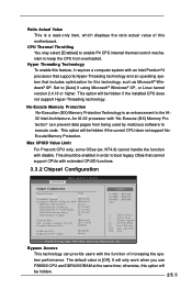
... using Microsoft® Windows® XP, or Linux kernel version 2.4.18 or higher. Bypass Access This technology can prevent data pages from overheated. otherwise, this motherboard. Set to the IA32 Intel Architecture. Ratio Actual Value This is a read-only item, which displays the ratio actual value of increasing the system performance.
... using Microsoft® Windows® XP, or Linux kernel version 2.4.18 or higher. Bypass Access This technology can prevent data pages from overheated. otherwise, this motherboard. Set to the IA32 Intel Architecture. Ratio Actual Value This is a read-only item, which displays the ratio actual value of increasing the system performance.

User Manual
Page 26
... by SPD Select [Enabled] will allow better tolerance for graphics memory. DRAM RAS# Precharge This controls the idle clocks after a precharge command is selected, the motherboard will detect the memory module(s) inserted and assigns appropriate frequency automatically. Memory Hole The default value of memory accessing. OnBoard LAN This allows you to...
... by SPD Select [Enabled] will allow better tolerance for graphics memory. DRAM RAS# Precharge This controls the idle clocks after a precharge command is selected, the motherboard will detect the memory module(s) inserted and assigns appropriate frequency automatically. Memory Hole The default value of memory accessing. OnBoard LAN This allows you to...
User Manual
Page 33
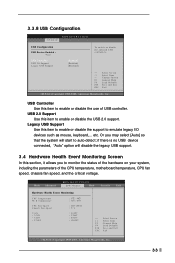
... hardware on your system, including the parameters of USB controller. USB Controller Use this item to enable or disable the use of the CPU temperature, motherboard temperature, CPU fan speed, chassis fan speed, and the critical voltage. 3.3.8 USB Configuration Advanced BIOS SETUP UTILITY USB Configuration USB Devices Enabled : None USB Controller...
... hardware on your system, including the parameters of USB controller. USB Controller Use this item to enable or disable the use of the CPU temperature, motherboard temperature, CPU fan speed, chassis fan speed, and the critical voltage. 3.3.8 USB Configuration Advanced BIOS SETUP UTILITY USB Configuration USB Devices Enabled : None USB Controller...
User Manual
Page 37
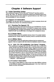
..." is enabled in your OS documentation for more about ASRock, welcome to visit ASRock's website at http://www.asrock.com; Since it . 4.2.4 "LGA 775 CPU Installation Live Demo" Program This motherboard is a new CPU socket interface that enhance the motherboard features. 4.2.1 Running The Support CD To begin using ..., use the setup procedures in order to reduce the risks of CPU and motherboard damages caused by improper handling, ASRock sincerely presents you may find this Live Demo, you need to contact ASRock or want to know more information. 4.2 Support CD Information The Support CD ...
..." is enabled in your OS documentation for more about ASRock, welcome to visit ASRock's website at http://www.asrock.com; Since it . 4.2.4 "LGA 775 CPU Installation Live Demo" Program This motherboard is a new CPU socket interface that enhance the motherboard features. 4.2.1 Running The Support CD To begin using ..., use the setup procedures in order to reduce the risks of CPU and motherboard damages caused by improper handling, ASRock sincerely presents you may find this Live Demo, you need to contact ASRock or want to know more information. 4.2 Support CD Information The Support CD ...

Quick Installation Guide
Page 1
... operation. Operation is subject to the following two conditions: (1) this device may not cause harmful interference, and (2) this guide, ASRock does not provide warranty of any kind, either expressed or implied, including but not limited to the implied warranties or conditions of ...transcribed, transmitted, or translated in any language, in any form or by any means, except duplication of documentation by ASRock. All rights reserved. 1 ASRock 775i65PE Motherboard English Products and corporate names appearing in this guide may or may appear in the guide or product. With respect to...
... operation. Operation is subject to the following two conditions: (1) this device may not cause harmful interference, and (2) this guide, ASRock does not provide warranty of any kind, either expressed or implied, including but not limited to the implied warranties or conditions of ...transcribed, transmitted, or translated in any language, in any form or by any means, except duplication of documentation by ASRock. All rights reserved. 1 ASRock 775i65PE Motherboard English Products and corporate names appearing in this guide may or may appear in the guide or product. With respect to...
Quick Installation Guide
Page 2
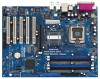
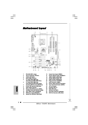
... JR1 / JL1 Jumpers 25 PCI Slots (PCI1- 5) 26 BIOS FWH Chip 27 AGP Slot (1.5V_AGP1) 28 ATX Power Connector (ATXPWR1) 29 CPU Fan Connector (CPU_FAN1) 2 ASRock 775i65PE Motherboard Motherboard Layout English 1 PS2_USB_PWR1 Jumper 2 ATX 12V Connector (ATX12V1) 3 775-Pin CPU Socket 4 North Bridge Controller 5 2 x 184-pin DDR DIMM Slots (Dual Channel A: DDR1, DDR3; Blue...
... JR1 / JL1 Jumpers 25 PCI Slots (PCI1- 5) 26 BIOS FWH Chip 27 AGP Slot (1.5V_AGP1) 28 ATX Power Connector (ATXPWR1) 29 CPU Fan Connector (CPU_FAN1) 2 ASRock 775i65PE Motherboard Motherboard Layout English 1 PS2_USB_PWR1 Jumper 2 ATX 12V Connector (ATX12V1) 3 775-Pin CPU Socket 4 North Bridge Controller 5 2 x 184-pin DDR DIMM Slots (Dual Channel A: DDR1, DDR3; Blue...
Quick Installation Guide
Page 3
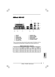
ASRock 8CH I/O 1 Parallel Port 2 RJ-45 Port 3 Side Speaker (Gray) 4 Rear Speaker (Black) 5 Central / Bass (Orange) 6 Line In (Light Blue) *7 Front Speaker (Lime) 8 Microphone (Pink) 9 USB 2.0 ... you use . See the table below for Audio Output Connection Audio Output Channels Front Speaker Rear Speaker Central / Bass (No. 7) (No. 4) (No. 5) 2 V -- -- 4 V V -- 6 V V V 8 V V V Side Speaker (No. 3) ---V 3 ASRock 775i65PE Motherboard English
ASRock 8CH I/O 1 Parallel Port 2 RJ-45 Port 3 Side Speaker (Gray) 4 Rear Speaker (Black) 5 Central / Bass (Orange) 6 Line In (Light Blue) *7 Front Speaker (Lime) 8 Microphone (Pink) 9 USB 2.0 ... you use . See the table below for Audio Output Connection Audio Output Channels Front Speaker Rear Speaker Central / Bass (No. 7) (No. 4) (No. 5) 2 V -- -- 4 V V -- 6 V V V 8 V V V Side Speaker (No. 3) ---V 3 ASRock 775i65PE Motherboard English
Quick Installation Guide
Page 4
... Form Factor: 12.0-in x 9.0-in Floppy Drive One Serial ATA (SATA) Data Cable One Serial ATA (SATA) HDD Power Cable (Optional) One ASRock 8CH I/O Shield 4 ASRock 775i65PE Motherboard English This Quick Installation Guide contains introduction of this manual occur, the updated version will be subject to quality and endurance. Introduction Thank you for a 3.5-...
... Form Factor: 12.0-in x 9.0-in Floppy Drive One Serial ATA (SATA) Data Cable One Serial ATA (SATA) HDD Power Cable (Optional) One ASRock 8CH I/O Shield 4 ASRock 775i65PE Motherboard English This Quick Installation Guide contains introduction of this manual occur, the updated version will be subject to quality and endurance. Introduction Thank you for a 3.5-...

