User Manual
Page 3
...5 1.1 Package Contents 5 1.2 Specifications 6 1.3 Motherboard Layout 9 1.4 ASRock I/O PlusTM 10 2 Installation 11 2.1 Screw Holes 11 2.2 Pre-installation Precautions 11 2.3 CPU Installation 12 2.4 Installation of CPU Fan and Heatsink 14 2.5 Installation of Memory Modules (DIMM 15 2.6 ...22 3.1 Introduction 22 3.1.1 BIOS Menu Bar 22 3.1.2 Navigation Keys 23 3.2 Main Screen 23 3.3 Advanced Screen 23 3.3.1 CPU Configuration 24 3.3.2 Chipset Configuration 26 3.3.3 ACPI Configuration 28 3.3.4 IDE Configuration 29 3.3.5 PCIPnP Configuration 31 3.3.6 Floppy Configuration 32 ...
...5 1.1 Package Contents 5 1.2 Specifications 6 1.3 Motherboard Layout 9 1.4 ASRock I/O PlusTM 10 2 Installation 11 2.1 Screw Holes 11 2.2 Pre-installation Precautions 11 2.3 CPU Installation 12 2.4 Installation of CPU Fan and Heatsink 14 2.5 Installation of Memory Modules (DIMM 15 2.6 ...22 3.1 Introduction 22 3.1.1 BIOS Menu Bar 22 3.1.2 Navigation Keys 23 3.2 Main Screen 23 3.3 Advanced Screen 23 3.3.1 CPU Configuration 24 3.3.2 Chipset Configuration 26 3.3.3 ACPI Configuration 28 3.3.4 IDE Configuration 29 3.3.5 PCIPnP Configuration 31 3.3.6 Floppy Configuration 32 ...

User Manual
Page 4
4 Software Support 38 4.1 Install Operating System 38 4.2 Support CD Information 38 4.2.1 Running Support CD 38 4.2.2 Drivers Menu 38 4.2.3 Utilities Menu 38 4.2.4 "LGA 775 CPU Installation Live Demo" Program.... 38 4.2.5 Contact Information 38 4
4 Software Support 38 4.1 Install Operating System 38 4.2 Support CD Information 38 4.2.1 Running Support CD 38 4.2.2 Drivers Menu 38 4.2.3 Utilities Menu 38 4.2.4 "LGA 775 CPU Installation Live Demo" Program.... 38 4.2.5 Contact Information 38 4
User Manual
Page 5
... Support CD. You may find the latest VGA cards and CPU support lists on ASRock website without notice. ASRock website http://www.asrock.com 1.1 Package Contents ASRock 775i65G Motherboard (Micro ATX Form Factor: 9.6-in x 8.0-in, 24.4 cm x 20.3 cm) ASRock 775i65G Quick Installation Guide ASRock 775i65G Support CD (including LGA 775 CPU Installation Live Demo) One 80-conductor Ultra ATA 66...
... Support CD. You may find the latest VGA cards and CPU support lists on ASRock website without notice. ASRock website http://www.asrock.com 1.1 Package Contents ASRock 775i65G Motherboard (Micro ATX Form Factor: 9.6-in x 8.0-in, 24.4 cm x 20.3 cm) ASRock 775i65G Quick Installation Guide ASRock 775i65G Support CD (including LGA 775 CPU Installation Live Demo) One 80-conductor Ultra ATA 66...
User Manual
Page 6
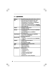
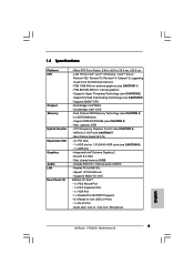
Supports EM64T CPU - Southbridge: Intel® ICH5 - Integrated Intel® Extreme Graphics 2 - DirectX 8.0 VGA - shared memory 96MB - Speed: 10/100 Ethernet - Supports Wake-On-LAN ASRock I /O - Micro ATX Form Factor: 9.6-in x 8.0-in, 24.4 cm x 20.3 cm - FSB 1066 MHz ...CAUTION 3) - capacity: 2GB - LGA 775 for 1.5V 8X/4X AGP card (see CAUTION 1) - Northbridge: Intel® 865G chipset - Max. ASRock U-COP (see CAUTION 6) - CPU Frequency Stepless Control (see CAUTION 7) - Boot Failure Guard (B.F.G.) - 3 x PCI slots - 1 x AGP slot for Intel® CoreTM 2 ...
Supports EM64T CPU - Southbridge: Intel® ICH5 - Integrated Intel® Extreme Graphics 2 - DirectX 8.0 VGA - shared memory 96MB - Speed: 10/100 Ethernet - Supports Wake-On-LAN ASRock I /O - Micro ATX Form Factor: 9.6-in x 8.0-in, 24.4 cm x 20.3 cm - FSB 1066 MHz ...CAUTION 3) - capacity: 2GB - LGA 775 for 1.5V 8X/4X AGP card (see CAUTION 1) - Northbridge: Intel® 865G chipset - Max. ASRock U-COP (see CAUTION 6) - CPU Frequency Stepless Control (see CAUTION 7) - Boot Failure Guard (B.F.G.) - 3 x PCI slots - 1 x AGP slot for Intel® CoreTM 2 ...

User Manual
Page 7
...- 1 x Floppy connector - 1 x IR header - 1 x COM port header - Voltage Monitoring: +12V, +5V, +3.3V, Vcore - Chassis Temperature Sensing - CPU Quiet Fan - Connector BIOS Feature Support CD Hardware Monitor OS Certifications - 2 x Serial ATA 1.5Gb/s connectors (No Support for possible damage caused by overclocking. 7 ACPI ...with USB4_5) (see CAUTION 9) - 4Mb AMI BIOS - AUX in header - Drivers, Utilities, AntiVirus Software (Trial Version) - CPU/Chassis FAN connector - 20 pin ATX power connector - 4 pin 12V power connector - Supports jumperfree - AMI Legal BIOS - ...
...- 1 x Floppy connector - 1 x IR header - 1 x COM port header - Voltage Monitoring: +12V, +5V, +3.3V, Vcore - Chassis Temperature Sensing - CPU Quiet Fan - Connector BIOS Feature Support CD Hardware Monitor OS Certifications - 2 x Serial ATA 1.5Gb/s connectors (No Support for possible damage caused by overclocking. 7 ACPI ...with USB4_5) (see CAUTION 9) - 4Mb AMI BIOS - AUX in header - Drivers, Utilities, AntiVirus Software (Trial Version) - CPU/Chassis FAN connector - 20 pin ATX power connector - 4 pin 12V power connector - Supports jumperfree - AMI Legal BIOS - ...
User Manual
Page 8
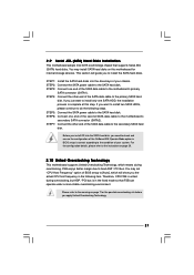
...at DDR320 if you resume the system, please check if the CPU fan on page 21 for proper installation. 5. About the setting of the system or damage the CPU. 7. This motherboard supports Untied Overclocking Technology. CPU FSB Frequency Memory Support Frequency 800 DDR266, DDR320*, DDR400 533 DDR266... motherboard supports Dual Channel Memory Technology. Before you use a 3.3V AGP card on page 15 for details. 4. Do NOT use an FSB800-CPU on this motherboard, it will automatically shutdown. It may not work properly under Microsoft® Windows® XP SP1 or SP2 / 2000 SP4...
...at DDR320 if you resume the system, please check if the CPU fan on page 21 for proper installation. 5. About the setting of the system or damage the CPU. 7. This motherboard supports Untied Overclocking Technology. CPU FSB Frequency Memory Support Frequency 800 DDR266, DDR320*, DDR400 533 DDR266... motherboard supports Dual Channel Memory Technology. Before you use a 3.3V AGP card on page 15 for details. 4. Do NOT use an FSB800-CPU on this motherboard, it will automatically shutdown. It may not work properly under Microsoft® Windows® XP SP1 or SP2 / 2000 SP4...
User Manual
Page 9
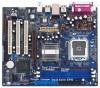
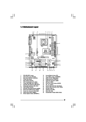
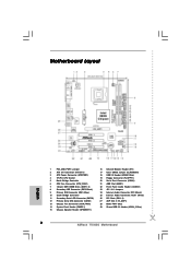
...: Mic In Top: RJ-45 USB 2.0 T: USB0 B: USB1 USB 2.0 T: USB2 B: USB3 USB 2.0 1 T: USB4 B: USB5 IDE2 Intel 865G Chipset 775i65G USB4_5 Super I/O ATXPWR1 4Mb BIOS PCI LAN CD1 AUX1 AUDIO CODEC AUDIO1 1 JR1 JL1 AGP8X 1.5V_AGP1 IDE1 RoHS CHA_FAN1 SATA PCI 1 PCI 2 USB2.0 PCI ... (9.6 in) 8 9 10 11 12 13 1 PS2_USB_PWR1 Jumper 2 ATX 12V Connector (ATX12V1) 3 ATX Power Connector (ATXPWR1) 4 775-Pin CPU Socket 5 North Bridge Controller 6 CPU Fan Connector (CPU_FAN1) 7 184-pin DDR DIMM Slots (DDR1- 2) 8 Secondary IDE Connector (IDE2, Black) 9 Primary IDE Connector (IDE1, Blue...
...: Mic In Top: RJ-45 USB 2.0 T: USB0 B: USB1 USB 2.0 T: USB2 B: USB3 USB 2.0 1 T: USB4 B: USB5 IDE2 Intel 865G Chipset 775i65G USB4_5 Super I/O ATXPWR1 4Mb BIOS PCI LAN CD1 AUX1 AUDIO CODEC AUDIO1 1 JR1 JL1 AGP8X 1.5V_AGP1 IDE1 RoHS CHA_FAN1 SATA PCI 1 PCI 2 USB2.0 PCI ... (9.6 in) 8 9 10 11 12 13 1 PS2_USB_PWR1 Jumper 2 ATX 12V Connector (ATX12V1) 3 ATX Power Connector (ATXPWR1) 4 775-Pin CPU Socket 5 North Bridge Controller 6 CPU Fan Connector (CPU_FAN1) 7 184-pin DDR DIMM Slots (DDR1- 2) 8 Secondary IDE Connector (IDE2, Black) 9 Primary IDE Connector (IDE1, Blue...

User Manual
Page 12
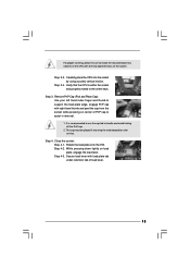
...2-2. Locate Pin1 and the two orientation key notches. Pin1 orientation key notch orientation key notch Pin1 alignment key alignment key 775-LAND CPU 12 775-Pin Socket black line black line DLifitsLeevnergUapgtoin9g0° the lever by the edges where are marked with IHS (Integrated Heat... Sink) up. Hold the CPU by depressing down and out on the socket. Insert the 775-LAND CPU: Step 2-1. Open the socket: CPU Marked Corner Step 1-1. Step 1. Step 2. 2.3 CPU Installation For the installation of Intel 775-LAND CPU, please follow the steps below. 775-Pin...
...2-2. Locate Pin1 and the two orientation key notches. Pin1 orientation key notch orientation key notch Pin1 alignment key alignment key 775-LAND CPU 12 775-Pin Socket black line black line DLifitsLeevnergUapgtoin9g0° the lever by the edges where are marked with IHS (Integrated Heat... Sink) up. Hold the CPU by depressing down and out on the socket. Insert the 775-LAND CPU: Step 2-1. Open the socket: CPU Marked Corner Step 1-1. Step 1. Step 2. 2.3 CPU Installation For the installation of Intel 775-LAND CPU, please follow the steps below. 775-Pin...
User Manual
Page 13
... the socket and properly mated to handle and avoid kicking off the PnP cap. 2. Rotate the load plate onto the IHS. Step 4-2. Verify that the CPU is recommended to use the cap tab to the orient keys. Close the socket: Step 4-1. Step 2-3. While pressing down lightly on center of PnP cap... to assist in removal. 1. For proper inserting, please ensure to match the two orientation key notches of the CPU with right hand thumb and peel the cap from the socket while pressing on load plate, engage the load lever. Carefully place the...
... the socket and properly mated to handle and avoid kicking off the PnP cap. 2. Rotate the load plate onto the IHS. Step 4-2. Verify that the CPU is recommended to use the cap tab to the orient keys. Close the socket: Step 4-1. Step 2-3. While pressing down lightly on center of PnP cap... to assist in removal. 1. For proper inserting, please ensure to match the two orientation key notches of the CPU with right hand thumb and peel the cap from the socket while pressing on load plate, engage the load lever. Carefully place the...
User Manual
Page 14
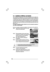
... and Heatsink This motherboard is an example to illustrate the installation of the heatsink for 775-LAND CPU. Apply thermal interface material onto center of your CPU fan and heatsink. Step 2. Step 1. Repeat with fan operation or contact other . Rotate the fastener clockwise, then press ...dissipate heat. Step 6. Before you installed the heatsink, you press down on the motherboard. Below is equipped with 775-Pin socket that the CPU and the heatsink are oriented on side closest to the instruction manuals of IHS on the motherboard (CPU_FAN1, see page 9, No. 6). For...
... and Heatsink This motherboard is an example to illustrate the installation of the heatsink for 775-LAND CPU. Apply thermal interface material onto center of your CPU fan and heatsink. Step 2. Step 1. Repeat with fan operation or contact other . Rotate the fastener clockwise, then press ...dissipate heat. Step 6. Before you installed the heatsink, you press down on the motherboard. Below is equipped with 775-Pin socket that the CPU and the heatsink are oriented on side closest to the instruction manuals of IHS on the motherboard (CPU_FAN1, see page 9, No. 6). For...
User Manual
Page 20
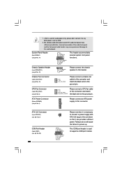
...front panel have different pin-definition. System Panel Header (9-pin PANEL1) (see p.9 No. 6) GND +12V CPU_FAN_SPEED FAN_SPEED_CONTROL Please connect a CPU fan cable to this connector and match the black wire to the ground pin. Incorrect connection of the audio front panel and the front ...header is used for audio power only, please don't connect it can provides sufficient power. 1. +5VA is used to support a COM port module. CPU Fan Connector (4-pin CPU_FAN1) (see p.9 No. 14) PLED+ PLEDPWRBTN# GND 1 DUMMY RESET# GND HDLEDHDLED+ This header accommodates several system front panel ...
...front panel have different pin-definition. System Panel Header (9-pin PANEL1) (see p.9 No. 6) GND +12V CPU_FAN_SPEED FAN_SPEED_CONTROL Please connect a CPU fan cable to this connector and match the black wire to the ground pin. Incorrect connection of the audio front panel and the front ...header is used for audio power only, please don't connect it can provides sufficient power. 1. +5VA is used to support a COM port module. CPU Fan Connector (4-pin CPU_FAN1) (see p.9 No. 14) PLED+ PLEDPWRBTN# GND 1 DUMMY RESET# GND HDLEDHDLED+ This header accommodates several system front panel ...
User Manual
Page 21
... is untied during overclocking, FSB enjoys better margin due to fixed AGP / PCI bus. You may set "CPU Host Frequency" option of the second SATA data cable to install the SATA hard disks. STEP 5: Connect the SATA power cable to the SATA hard ..., please continue to check and ensure the configuration of your chassis. STEP 1: Install the SATA hard disks into the SATA hard disk, you the actual CPU host frequency in the following steps. If you want to the primary SATA hard disk. Before you install OS into the drive bays of the...
... is untied during overclocking, FSB enjoys better margin due to fixed AGP / PCI bus. You may set "CPU Host Frequency" option of the second SATA data cable to install the SATA hard disks. STEP 5: Connect the SATA power cable to the SATA hard ..., please continue to check and ensure the configuration of your chassis. STEP 1: Install the SATA hard disks into the SATA hard disk, you the actual CPU host frequency in the following steps. If you want to the primary SATA hard disk. Before you install OS into the drive bays of the...
User Manual
Page 23
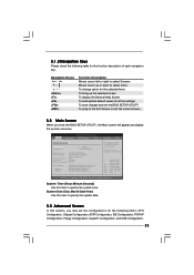
...Monitor Boot System Overview System Time System Date [14:00:09] [Fri 03/24/2006] BIOS Version : 775i65G BIOS P1.00 Processor Type : Intel (R) CPU 3.40 GHz (64bit supported) Processor Speed : 3400 Cache Size : 1024KB Microcode Update : F34/17 Total ... configurations for the following table for the function description of each navigation key. 3.1.2 Navigation Keys Please check the following items: CPU Configuration, Chipset Configuration, ACPI Configuration, IDE Configuration, PCIPnP Configuration, Floppy Configuration, SuperIO Configuration, and USB Configuration. 23 Navigation ...
...Monitor Boot System Overview System Time System Date [14:00:09] [Fri 03/24/2006] BIOS Version : 775i65G BIOS P1.00 Processor Type : Intel (R) CPU 3.40 GHz (64bit supported) Processor Speed : 3400 Cache Size : 1024KB Microcode Update : F34/17 Total ... configurations for the following table for the function description of each navigation key. 3.1.2 Navigation Keys Please check the following items: CPU Configuration, Chipset Configuration, ACPI Configuration, IDE Configuration, PCIPnP Configuration, Floppy Configuration, SuperIO Configuration, and USB Configuration. 23 Navigation ...
User Manual
Page 24
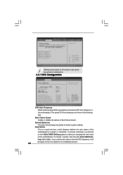
...will find an item Ratio CMOS Setting appears to allow you will be equal to the core speed of the installed processor. 24 CPU Thermal Throttling No-Excute Memory Protection Hyper Threading Technology Intel (R) SpeedStep(tm) tech. [Disabled] [Disabled] [Enabled] [Enabled] ... Boot Security Exit Advanced Settings WARNING : Setting wrong values in below sections may cause the system to malfunction. 3.3.1 CPU Configuration BIOS SETUP UTILITY Advanced CPU Configuration CPU Host Frequency Actual Frequency (MHz) Boot Failure Guard Spread Spectrum Ratio Status Ratio Actual Value [Auto] [200] [...
...will find an item Ratio CMOS Setting appears to allow you will be equal to the core speed of the installed processor. 24 CPU Thermal Throttling No-Excute Memory Protection Hyper Threading Technology Intel (R) SpeedStep(tm) tech. [Disabled] [Disabled] [Enabled] [Enabled] ... Boot Security Exit Advanced Settings WARNING : Setting wrong values in below sections may cause the system to malfunction. 3.3.1 CPU Configuration BIOS SETUP UTILITY Advanced CPU Configuration CPU Host Frequency Actual Frequency (MHz) Boot Failure Guard Spread Spectrum Ratio Status Ratio Actual Value [Auto] [200] [...
User Manual
Page 25
...Auto], you changing the ratio value of this feature, it requires a computer system with disable. This should be hidden if the installed CPU does not support Intel (R) Virtualization Technology. No-Excute Memory Protection No-Execution (NX) Memory Protection Technology is Intel's new power saving technology.... Max CPUID Value Limit For Prescott CPU only, some OSes (ex. This option will find this item appear to allow you need to set to [Enabled], a VMM (Virtual...
...Auto], you changing the ratio value of this feature, it requires a computer system with disable. This should be hidden if the installed CPU does not support Intel (R) Virtualization Technology. No-Excute Memory Protection No-Execution (NX) Memory Protection Technology is Intel's new power saving technology.... Max CPUID Value Limit For Prescott CPU only, some OSes (ex. This option will find this item appear to allow you need to set to [Enabled], a VMM (Virtual...

User Manual
Page 34
...65 C. Target Fan Speed Use this option to allow you adjusting them. BIOS SETUP UTILITY Main Advanced H/W Monitor Boot Security Exit Hardware Health Event Monitoring CPU Temperature M / B Temperature CPU Fan Speed Chassis Fan Speed Vcore + 3.30V + 5.00V + 12.00V : 45 C / 98 F : 31 C / 87 F : 2463 RPM : ... fan speed, and the critical voltage. The default value is [50]. The default value is [2], which means the error of the target CPU temperature will operate in full speed. Tolerance ( C) The default value of tolerance is [Disabled]. Configuration options: [Fast], [Middle] and...
...65 C. Target Fan Speed Use this option to allow you adjusting them. BIOS SETUP UTILITY Main Advanced H/W Monitor Boot Security Exit Hardware Health Event Monitoring CPU Temperature M / B Temperature CPU Fan Speed Chassis Fan Speed Vcore + 3.30V + 5.00V + 12.00V : 45 C / 98 F : 31 C / 87 F : 2463 RPM : ... fan speed, and the critical voltage. The default value is [50]. The default value is [2], which means the error of the target CPU temperature will operate in full speed. Tolerance ( C) The default value of tolerance is [Disabled]. Configuration options: [Fast], [Middle] and...
User Manual
Page 38
... the Support CD to be damaged by improper handling, ASRock sincerely presents you a clear installation guide through the following path: ..\ MPEGAV \ LGA775INST.DAT 4.2.5 Contact Information If you may check this "LGA 775 CPU Installation Live Demo". Please install the necessary drivers to ...using the support CD, insert the CD into your OS documentation for more about ASRock, welcome to reduce the risks of LGA 775 CPU in order to visit ASRock's website at http://www.asrock.com; Chapter 4 Software Support 4.1 Install Operating System This motherboard supports various Microsoft...
... the Support CD to be damaged by improper handling, ASRock sincerely presents you a clear installation guide through the following path: ..\ MPEGAV \ LGA775INST.DAT 4.2.5 Contact Information If you may check this "LGA 775 CPU Installation Live Demo". Please install the necessary drivers to ...using the support CD, insert the CD into your OS documentation for more about ASRock, welcome to reduce the risks of LGA 775 CPU in order to visit ASRock's website at http://www.asrock.com; Chapter 4 Software Support 4.1 Install Operating System This motherboard supports various Microsoft...
Quick Installation Guide
Page 2
Motherboard Layout English 1 PS2_USB_PWR1 Jumper 2 ATX 12V Connector (ATX12V1) 3 ATX Power Connector (ATXPWR1) 4 775-Pin CPU Socket 5 North Bridge Controller 6 CPU Fan Connector (CPU_FAN1) 7 184-pin DDR DIMM Slots (DDR1- 2) 8 Secondary IDE Connector (IDE2, Black) 9 Primary IDE Connector (IDE1, Blue) 10 South Bridge Controller 11 Secondary ... (Black) 25 Internal Audio Connector: AUX1 (White) 26 PCI Slots (PCI1- 3) 27 AGP Slot (1.5V_AGP1) 28 BIOS FWH Chip 29 Shared USB 2.0 Header (USB4_5, Blue) 2 ASRock 775i65G Motherboard
Motherboard Layout English 1 PS2_USB_PWR1 Jumper 2 ATX 12V Connector (ATX12V1) 3 ATX Power Connector (ATXPWR1) 4 775-Pin CPU Socket 5 North Bridge Controller 6 CPU Fan Connector (CPU_FAN1) 7 184-pin DDR DIMM Slots (DDR1- 2) 8 Secondary IDE Connector (IDE2, Black) 9 Primary IDE Connector (IDE1, Blue) 10 South Bridge Controller 11 Secondary ... (Black) 25 Internal Audio Connector: AUX1 (White) 26 PCI Slots (PCI1- 3) 27 AGP Slot (1.5V_AGP1) 28 BIOS FWH Chip 29 Shared USB 2.0 Header (USB4_5, Blue) 2 ASRock 775i65G Motherboard
Quick Installation Guide
Page 4
...8.0-in, 24.4 cm x 20.3 cm) ASRock 775i65G Quick Installation Guide ASRock 775i65G Support CD One 80-conductor Ultra ATA 66/100 IDE Ribbon Cable One Ribbon Cable for purchasing ASRock 775i65G motherboard, a reliable motherboard produced under ASRock's consistently stringent quality control. This Quick Installation ... (SATA) HDD Power Cable (Optional) One ASRock I/O PlusTM Shield One COM Port Bracket One ASRock MR Card (Optional) 4 ASRock 775i65G Motherboard English You may find the latest VGA cards and CPU support lists on ASRock website without notice. More detailed information of the...
...8.0-in, 24.4 cm x 20.3 cm) ASRock 775i65G Quick Installation Guide ASRock 775i65G Support CD One 80-conductor Ultra ATA 66/100 IDE Ribbon Cable One Ribbon Cable for purchasing ASRock 775i65G motherboard, a reliable motherboard produced under ASRock's consistently stringent quality control. This Quick Installation ... (SATA) HDD Power Cable (Optional) One ASRock I/O PlusTM Shield One COM Port Bracket One ASRock MR Card (Optional) 4 ASRock 775i65G Motherboard English You may find the latest VGA cards and CPU support lists on ASRock website without notice. More detailed information of the...
Quick Installation Guide
Page 5
...Core Kentsfield processors - ASRock U-COP (see CAUTION 6) - Integrated Intel® Extreme Graphics 2 - Max. Supports Wake-On-LAN ASRock I /O - Supports EM64T CPU - CPU Frequency Stepless Control (see CAUTION 7) - Audio Jack: Line In / Line Out / Microphone English 5 ASRock 775i65G Motherboard Support DDR400/...Memory Technology (see CAUTION 2) - Micro ATX Form Factor: 9.6-in x 8.0-in, 24.4 cm x 20.3 cm - 1.2 Specifications Platform CPU Chipset Memory Hybrid Booster Expansion Slot Graphics Audio LAN Rear Panel I /O PlusTM - 1 x PS/2 Mouse Port - 1 x PS/2 ...
...Core Kentsfield processors - ASRock U-COP (see CAUTION 6) - Integrated Intel® Extreme Graphics 2 - Max. Supports Wake-On-LAN ASRock I /O - Supports EM64T CPU - CPU Frequency Stepless Control (see CAUTION 7) - Audio Jack: Line In / Line Out / Microphone English 5 ASRock 775i65G Motherboard Support DDR400/...Memory Technology (see CAUTION 2) - Micro ATX Form Factor: 9.6-in x 8.0-in, 24.4 cm x 20.3 cm - 1.2 Specifications Platform CPU Chipset Memory Hybrid Booster Expansion Slot Graphics Audio LAN Rear Panel I /O PlusTM - 1 x PS/2 Mouse Port - 1 x PS/2 ...


