User Manual
Page 3
... Serial ATA (SATA) Hard Disks Installation 21 2.10 Untied Overclocking Technology 21 3 BIOS SETUP UTILITY 22 3.1 Introduction 22 3.1.1 BIOS Menu Bar 22 3.1.2 Navigation Keys 23 3.2 Main Screen 23 3.3 Advanced Screen 23 3.3.1 CPU Configuration 24 3.3.2 Chipset Configuration 26 3.3.3 ACPI Configuration 28 3.3.4 IDE Configuration 29 3.3.5 PCIPnP Configuration 31 3.3.6 Floppy Configuration 32 3.3.7 Super IO Configuration 32 3.3.8 USB Configuration 33 3.4 Hardware Health Event Monitoring Screen 34 3.5 Boot Screen 35 3.5.1 Boot Settings Configuration 35 3.5.2 Boot Device Priority...
... Serial ATA (SATA) Hard Disks Installation 21 2.10 Untied Overclocking Technology 21 3 BIOS SETUP UTILITY 22 3.1 Introduction 22 3.1.1 BIOS Menu Bar 22 3.1.2 Navigation Keys 23 3.2 Main Screen 23 3.3 Advanced Screen 23 3.3.1 CPU Configuration 24 3.3.2 Chipset Configuration 26 3.3.3 ACPI Configuration 28 3.3.4 IDE Configuration 29 3.3.5 PCIPnP Configuration 31 3.3.6 Floppy Configuration 32 3.3.7 Super IO Configuration 32 3.3.8 USB Configuration 33 3.4 Hardware Health Event Monitoring Screen 34 3.5 Boot Screen 35 3.5.1 Boot Settings Configuration 35 3.5.2 Boot Device Priority...
User Manual
Page 5
...) One 80-conductor Ultra ATA 66/100 IDE Ribbon Cable One Ribbon Cable for purchasing ASRock 775i65G motherboard, a reliable motherboard produced under ASRock's consistently stringent quality control. It delivers excellent performance with robust design conforming to ASRock's commitment to the hardware installation. Chapter 1 Introduction Thank you for a 3.5-in Floppy Drive One Serial ATA (SATA) Data Cable (Optional) One Serial ATA (SATA) HDD Power Cable (Optional) One ASRock I/O PlusTM Shield One COM Port Bracket One ASRock MR Card (Optional) 5
...) One 80-conductor Ultra ATA 66/100 IDE Ribbon Cable One Ribbon Cable for purchasing ASRock 775i65G motherboard, a reliable motherboard produced under ASRock's consistently stringent quality control. It delivers excellent performance with robust design conforming to ASRock's commitment to the hardware installation. Chapter 1 Introduction Thank you for a 3.5-in Floppy Drive One Serial ATA (SATA) Data Cable (Optional) One Serial ATA (SATA) HDD Power Cable (Optional) One ASRock I/O PlusTM Shield One COM Port Bracket One ASRock MR Card (Optional) 5
User Manual
Page 8
... CPU fan on this motherboard offers stepless control, it is supported only when you implement Dual Channel Memory Technology, make sure to read "Un- Although this motherboard, please adopt a DDR400 CL2.5 memory module. 2. Frequencies other than the recommended CPU bus frequencies may cause permanent damage! 9. Do NOT use a FSB1066-CPU on the motherboard functions properly and unplug the power cord, then plug it will automatically shutdown. Please read the installation guide of memory...
... CPU fan on this motherboard offers stepless control, it is supported only when you implement Dual Channel Memory Technology, make sure to read "Un- Although this motherboard, please adopt a DDR400 CL2.5 memory module. 2. Frequencies other than the recommended CPU bus frequencies may cause permanent damage! 9. Do NOT use a FSB1066-CPU on the motherboard functions properly and unplug the power cord, then plug it will automatically shutdown. Please read the installation guide of memory...

User Manual
Page 9
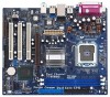
...) 3 ATX Power Connector (ATXPWR1) 4 775-Pin CPU Socket 5 North Bridge Controller 6 CPU Fan Connector (CPU_FAN1) 7 184-pin DDR DIMM Slots (DDR1- 2) 8 Secondary IDE Connector (IDE2, Black) 9 Primary IDE Connector (IDE1, Blue) 10 South Bridge Controller 11 Secondary Serial ATA Connector (SATA2) 12 Primary Serial ATA Connector (SATA1) 13 Chassis Fan Connector (CHA_FAN1) 14 System Panel Header (PANEL1) 15 Chassis Speaker Header (SPEAKER 1) 16 Infrared Module Header (IR1) 17 Clear CMOS Jumper (CLRCMOS0) 18 USB 2.0 Header (USB67, Blue) 19 Floppy Connector (FLOPPY1) 20 Serial Port...
...) 3 ATX Power Connector (ATXPWR1) 4 775-Pin CPU Socket 5 North Bridge Controller 6 CPU Fan Connector (CPU_FAN1) 7 184-pin DDR DIMM Slots (DDR1- 2) 8 Secondary IDE Connector (IDE2, Black) 9 Primary IDE Connector (IDE1, Blue) 10 South Bridge Controller 11 Secondary Serial ATA Connector (SATA2) 12 Primary Serial ATA Connector (SATA1) 13 Chassis Fan Connector (CHA_FAN1) 14 System Panel Header (PANEL1) 15 Chassis Speaker Header (SPEAKER 1) 16 Infrared Module Header (IR1) 17 Clear CMOS Jumper (CLRCMOS0) 18 USB 2.0 Header (USB67, Blue) 19 Floppy Connector (FLOPPY1) 20 Serial Port...

User Manual
Page 19
... This header supports an optional wireless transmitting and receiving infrared module. Serial ATA (SATA) Power Cable (Optional) connect to the SATA HDD power connector connect to the power supply Please connect the black end of SATA power cable to the power connector of the power supply. O U T- Then connect the white end of audio devices. 19 R MIC-POWER MIC This is available to receive stereo audio input from sound sources such as a CD-ROM, DVD-ROM, TV tuner card, or MPEG card. When using the front panel USB ports by...
... This header supports an optional wireless transmitting and receiving infrared module. Serial ATA (SATA) Power Cable (Optional) connect to the SATA HDD power connector connect to the power supply Please connect the black end of SATA power cable to the power connector of the power supply. O U T- Then connect the white end of audio devices. 19 R MIC-POWER MIC This is available to receive stereo audio input from sound sources such as a CD-ROM, DVD-ROM, TV tuner card, or MPEG card. When using the front panel USB ports by...

User Manual
Page 20
... FAN_SPEED_CONTROL Please connect a CPU fan cable to this header. CPU Fan Connector (4-pin CPU_FAN1) (see p.9 No. 15) 1 SPEAKER DUMMY DUMMY +5V Please connect the chassis speaker to this connector and match the black wire to the ground pin. Incorrect connection of the audio front panel and the front panel audio header may cause permanent damage to this connector and match the black wire to the ground pin. Chassis Fan Connector (3-pin CHA_FAN1) (see p.9 No. 3) Please connect an ATX power supply to this connector so...
... FAN_SPEED_CONTROL Please connect a CPU fan cable to this header. CPU Fan Connector (4-pin CPU_FAN1) (see p.9 No. 15) 1 SPEAKER DUMMY DUMMY +5V Please connect the chassis speaker to this connector and match the black wire to the ground pin. Incorrect connection of the audio front panel and the front panel audio header may cause permanent damage to this connector and match the black wire to the ground pin. Chassis Fan Connector (3-pin CHA_FAN1) (see p.9 No. 3) Please connect an ATX power supply to this connector so...

User Manual
Page 21
... the motherboard's secondary SATA connector (SATA2). STEP 3: Connect one end of your chassis. If you the actual CPU host frequency in BIOS setup is correct according to the condition of the second SATA data cable to [Auto], which means during overclocking, but AGP / PCI bus is in the fixed mode so that supports Serial ATA (SATA) hard disks. STEP 5: Connect the SATA power cable to the SATA hard disk. This section will show you just want to install two SATA HDDs...
... the motherboard's secondary SATA connector (SATA2). STEP 3: Connect one end of your chassis. If you the actual CPU host frequency in BIOS setup is correct according to the condition of the second SATA data cable to [Auto], which means during overclocking, but AGP / PCI bus is in the fixed mode so that supports Serial ATA (SATA) hard disks. STEP 5: Connect the SATA power cable to the SATA hard disk. This section will show you just want to install two SATA HDDs...

User Manual
Page 22
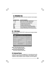
... PCI features Boot To set up the default system device to locate and load the Operating System Security To set up the security features Chipset To set up the computer. Chapter 3 BIOS SETUP UTILITY 3.1 Introduction This section explains how to use the BIOS SETUP UTILITY to configure your screen. 3.1.1 BIOS Menu Bar The top of the screen has a menu bar with its test routines. You may run the BIOS SETUP UTILITY when you wish to enter the BIOS SETUP UTILITY...
... PCI features Boot To set up the default system device to locate and load the Operating System Security To set up the security features Chipset To set up the computer. Chapter 3 BIOS SETUP UTILITY 3.1 Introduction This section explains how to use the BIOS SETUP UTILITY to configure your screen. 3.1.1 BIOS Menu Bar The top of the screen has a menu bar with its test routines. You may run the BIOS SETUP UTILITY when you wish to enter the BIOS SETUP UTILITY...
User Manual
Page 23
... you enter the BIOS SETUP UTILITY, the Main screen will appear and display the system overview Main Advanced BIOS SETUP UTILITY H/W Monitor Boot System Overview System Time System Date [14:00:09] [Fri 03/24/2006] BIOS Version : 775i65G BIOS P1.00 Processor Type : Intel (R) CPU 3.40 GHz (64bit supported) Processor Speed : 3400 Cache Size : 1024KB Microcode Update : F34/17 Total Memory DIMM 1 DIMM 2 : 512MB with 8MB shared memory Dual-Channel Memory Mode : 256MB/166MHz (DDR333) : 256MB/166MHz (DDR333) Security Exit Use [Enter...
... you enter the BIOS SETUP UTILITY, the Main screen will appear and display the system overview Main Advanced BIOS SETUP UTILITY H/W Monitor Boot System Overview System Time System Date [14:00:09] [Fri 03/24/2006] BIOS Version : 775i65G BIOS P1.00 Processor Type : Intel (R) CPU 3.40 GHz (64bit supported) Processor Speed : 3400 Cache Size : 1024KB Microcode Update : F34/17 Total Memory DIMM 1 DIMM 2 : 512MB with 8MB shared memory Dual-Channel Memory Mode : 256MB/166MHz (DDR333) : 256MB/166MHz (DDR333) Security Exit Use [Enter...

User Manual
Page 24
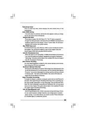
... actual CPU host frequency will be equal to the core speed of this motherboard is "Locked" or "Unlocked". CPU Configuration Chipset Configuration ACPI Configuration IDE Configuration PCIPnP Configuration Floppy Configuration SuperIO Configuration USB Configuration Configure CPU Select Screen Select Item Enter Go to malfunction. 3.3.1 CPU Configuration BIOS SETUP UTILITY Advanced CPU Configuration CPU Host Frequency Actual Frequency (MHz) Boot Failure Guard Spread Spectrum Ratio Status Ratio Actual Value [Auto] [200] [Enabled] [Auto] : Locked : 16 Enhance Halt State Max CPUID Value...
... actual CPU host frequency will be equal to the core speed of this motherboard is "Locked" or "Unlocked". CPU Configuration Chipset Configuration ACPI Configuration IDE Configuration PCIPnP Configuration Floppy Configuration SuperIO Configuration USB Configuration Configure CPU Select Screen Select Item Enter Go to malfunction. 3.3.1 CPU Configuration BIOS SETUP UTILITY Advanced CPU Configuration CPU Host Frequency Actual Frequency (MHz) Boot Failure Guard Spread Spectrum Ratio Status Ratio Actual Value [Auto] [200] [Enabled] [Auto] : Locked : 16 Enhance Halt State Max CPUID Value...
User Manual
Page 25
... processors support the Halt State (C1). Max CPUID Value Limit For Prescott CPU only, some OSes (ex. NT4.0) cannot handle the function with "No Execute (NX) Memory Protection" can switch between multiple frequency and voltage points to execute code. Ratio CMOS Setting If the ratio status is Intel's new power saving technology. CPU Thermal Throttling You may select [Enabled] to enable P4 CPU internal thermal control mechanism to [Enabled] if using...
... processors support the Halt State (C1). Max CPUID Value Limit For Prescott CPU only, some OSes (ex. NT4.0) cannot handle the function with "No Execute (NX) Memory Protection" can switch between multiple frequency and voltage points to execute code. Ratio CMOS Setting If the ratio status is Intel's new power saving technology. CPU Thermal Throttling You may select [Enabled] to enable P4 CPU internal thermal control mechanism to [Enabled] if using...
User Manual
Page 28
... mode. PS/2 Keyboard Power On Use this item to enable or disable RTC (Real Time Clock) to boot up when the power recovers. 3.3.3 ACPI Configuration BIOS SETUP UTILITY Advanced ACPI Configuration Suspend To RAM Restore on the system from the power-soft-off when the power recovers. Ring-In Power On Use this feature if the system supports it. Suspend to RAM This field allows you to turn on AC / Power Loss Ring-In Power On PCI Devices Power...
... mode. PS/2 Keyboard Power On Use this item to enable or disable RTC (Real Time Clock) to boot up when the power recovers. 3.3.3 ACPI Configuration BIOS SETUP UTILITY Advanced ACPI Configuration Suspend To RAM Restore on the system from the power-soft-off when the power recovers. Ring-In Power On Use this feature if the system supports it. Suspend to RAM This field allows you to turn on AC / Power Loss Ring-In Power On PCI Devices Power...
User Manual
Page 29
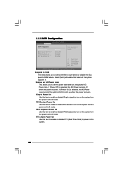
... supports four IDE devices under legacy OS (Windows ME / 98SE), you to select between [Pri IDE + SATA] and [SATA + Sec IDE]. 3.3.4 IDE Configuration BIOS SETUP UTILITY Advanced IDE Configuration OnBoard IDE Operate Mode OnBoard IDE Controller Primary IDE Master Primary IDE Slave Secondary IDE Master Secondary IDE Slave SATA1 SATA2 [Enhanced Mode] [Both] [Hard Disk] [Not Detected] [Not Detected] [Not Detected] [Not Detected] [Not Detected] Set [Compatible Mode] when both Legacy OS (MS-DOS, Win Me / 98SE) and SATA device are used, you also need to [SATA + Sec IDE...
... supports four IDE devices under legacy OS (Windows ME / 98SE), you to select between [Pri IDE + SATA] and [SATA + Sec IDE]. 3.3.4 IDE Configuration BIOS SETUP UTILITY Advanced IDE Configuration OnBoard IDE Operate Mode OnBoard IDE Controller Primary IDE Master Primary IDE Slave Secondary IDE Master Secondary IDE Slave SATA1 SATA2 [Enhanced Mode] [Both] [Hard Disk] [Not Detected] [Not Detected] [Not Detected] [Not Detected] [Not Detected] Set [Compatible Mode] when both Legacy OS (MS-DOS, Win Me / 98SE) and SATA device are used, you also need to [SATA + Sec IDE...

User Manual
Page 30
... applied to the configurations of IDE device. [Auto]: Select [Auto] to automatically detect the hard disk drive. This is used for IDE ARMD (ATAPI Removable Media Device), such as FDISK, to partition and format the new IDE hard disk drives. for a hard disk > 512 MB under DOS and Windows; IDE Device Configuration You may set the partition of device connected to the system. +F1 F9 F10 ESC Select Screen Select Item Change Option General Help Load Defaults Save and Exit...
... applied to the configurations of IDE device. [Auto]: Select [Auto] to automatically detect the hard disk drive. This is used for IDE ARMD (ATAPI Removable Media Device), such as FDISK, to partition and format the new IDE hard disk drives. for a hard disk > 512 MB under DOS and Windows; IDE Device Configuration You may set the partition of device connected to the system. +F1 F9 F10 ESC Select Screen Select Item Change Option General Help Load Defaults Save and Exit...

User Manual
Page 31
...PIO Mode Use this item to enable or disable the S.M.A.R.T. (Self-Monitoring, Analysis, and Reporting Technology) feature. It is [Auto]. Block (Multi-Sector Transfer) The default value of PCI clocks for compatible IDE devices. Configuration options: [Disabled], [Auto], [Enabled]. 32-Bit Data Transfer Use this item to enable 32-bit access to maximize the IDE hard disk data transfer rate. 3.3.5 PCIPnP Configuration BIOS SETUP UTILITY Advanced PCI / PnP Configuration PCI Latency Timer PCI IDE BusMaster [32] [Enabled] Value in units of this item to enable or disable the PCI IDE...
...PIO Mode Use this item to enable or disable the S.M.A.R.T. (Self-Monitoring, Analysis, and Reporting Technology) feature. It is [Auto]. Block (Multi-Sector Transfer) The default value of PCI clocks for compatible IDE devices. Configuration options: [Disabled], [Auto], [Enabled]. 32-Bit Data Transfer Use this item to enable 32-bit access to maximize the IDE hard disk data transfer rate. 3.3.5 PCIPnP Configuration BIOS SETUP UTILITY Advanced PCI / PnP Configuration PCI Latency Timer PCI IDE BusMaster [32] [Enabled] Value in units of this item to enable or disable the PCI IDE...

User Manual
Page 32
... your floppy drive. 3.3.6 Floppy Configuration In this section, you may configure the type of floppy drive connected to the system. +F1 F9 F10 ESC Select Screen Select Item Change Option General Help Load Defaults Save and Exit Exit v02.54 (C) Copyright 1985-2003, American Megatrends, Inc. 3.3.7 Super IO Configuration BIOS SETUP UTILITY Advanced Configure Super IO Chipset OnBoard Floppy Controller Serial Port Address Infrared Port Address Parallel Port Address Parallel Port Mode EPP Version ECP Mode DMA Channel Parallel Port IRQ [Enabled] [3F8 / IRQ4] [Disabled...
... your floppy drive. 3.3.6 Floppy Configuration In this section, you may configure the type of floppy drive connected to the system. +F1 F9 F10 ESC Select Screen Select Item Change Option General Help Load Defaults Save and Exit Exit v02.54 (C) Copyright 1985-2003, American Megatrends, Inc. 3.3.7 Super IO Configuration BIOS SETUP UTILITY Advanced Configure Super IO Chipset OnBoard Floppy Controller Serial Port Address Infrared Port Address Parallel Port Address Parallel Port Mode EPP Version ECP Mode DMA Channel Parallel Port IRQ [Enabled] [3F8 / IRQ4] [Disabled...
User Manual
Page 33
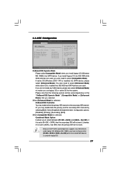
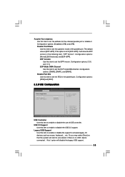
Parallel Port Mode Use this item to set to [ECP+EPP], it . The default value is no USB device connected, "Auto" option will disable the legacy USB support. 33 If this option is set the ECP mode DMA channel. Configuration options: [IRQ5] and [IRQ7]. 3.3.8 USB Configuration BIOS SETUP UTILITY Advanced USB Configuration USB Controller USB 2.0 Support Legacy USB Support [Enabled] [Enabled] [Disabled] To enable or disable the onboard USB controllers. +F1 F9 F10 ESC Select Screen Select Item Change Option General Help Load Defaults Save and Exit Exit v02.54 (C) Copyright 1985-2003, ...
Parallel Port Mode Use this item to set to [ECP+EPP], it . The default value is no USB device connected, "Auto" option will disable the legacy USB support. 33 If this option is set the ECP mode DMA channel. Configuration options: [IRQ5] and [IRQ7]. 3.3.8 USB Configuration BIOS SETUP UTILITY Advanced USB Configuration USB Controller USB 2.0 Support Legacy USB Support [Enabled] [Enabled] [Disabled] To enable or disable the onboard USB controllers. +F1 F9 F10 ESC Select Screen Select Item Change Option General Help Load Defaults Save and Exit Exit v02.54 (C) Copyright 1985-2003, ...

User Manual
Page 35
Main Advanced BIOS SETUP UTILITY H/W Monitor Boot Security Exit Boot Settings Boot Settings Configuration Boot Device Priority Hard Disk Drives Removable Drives CD / DVD Drives Configure Settings during System Boot. Boot Up Num-Lock If this item is set to enable or disable the Boot From Network feature. Boot From Network Use this item to [On], it will automatically activate the Numeric Lock function after boot-up. 35 3.5 Boot Screen In this section, it will display the available devices on your system for you to Sub Screen F1 General...
Main Advanced BIOS SETUP UTILITY H/W Monitor Boot Security Exit Boot Settings Boot Settings Configuration Boot Device Priority Hard Disk Drives Removable Drives CD / DVD Drives Configure Settings during System Boot. Boot Up Num-Lock If this item is set to enable or disable the Boot From Network feature. Boot From Network Use this item to [On], it will automatically activate the Numeric Lock function after boot-up. 35 3.5 Boot Screen In this section, it will display the available devices on your system for you to Sub Screen F1 General...
User Manual
Page 36
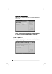
... boot sequence from the available devices. BIOS SETUP UTILITY Main Advanced H/W Monitor Boot Security Exit Security Settings Supervisor Password : Not Installed User Password : Not Installed Change Supervisor Password Change User Password Clear User Password Install or Change the password. BIOS SETUP UTILITY Boot Boot Device Priority 1st Boot Device 2nd Boot Device 3rd Boot Device [1st FLOPPY DRIVE] [HDD: PM-MAXTOR 6L08] [CD / DVD] Specifies the boot sequence from the available devices for the hard disk drives, the removable drives, and the CD/DVD drives. 3.6 Security Screen...
... boot sequence from the available devices. BIOS SETUP UTILITY Main Advanced H/W Monitor Boot Security Exit Security Settings Supervisor Password : Not Installed User Password : Not Installed Change Supervisor Password Change User Password Clear User Password Install or Change the password. BIOS SETUP UTILITY Boot Boot Device Priority 1st Boot Device 2nd Boot Device 3rd Boot Device [1st FLOPPY DRIVE] [HDD: PM-MAXTOR 6L08] [CD / DVD] Specifies the boot sequence from the available devices for the hard disk drives, the removable drives, and the CD/DVD drives. 3.6 Security Screen...
User Manual
Page 38
...; to your CD-ROM drive. Please install the necessary drivers to display the menus. 4.2.2 Drivers Menu The Drivers Menu shows the available devices drivers if the system detects installed devices. Chapter 4 Software Support 4.1 Install Operating System This motherboard supports various Microsoft® Windows® operating systems: 98SE/ME/2000/XP. Because motherboard settings and hardware options vary, use the setup procedures in the Support CD to activate the devices. 4.2.3 Utilities Menu The Utilities Menu shows the applications software that Intel has...
...; to your CD-ROM drive. Please install the necessary drivers to display the menus. 4.2.2 Drivers Menu The Drivers Menu shows the available devices drivers if the system detects installed devices. Chapter 4 Software Support 4.1 Install Operating System This motherboard supports various Microsoft® Windows® operating systems: 98SE/ME/2000/XP. Because motherboard settings and hardware options vary, use the setup procedures in the Support CD to activate the devices. 4.2.3 Utilities Menu The Utilities Menu shows the applications software that Intel has...


