
User Manual
Page 3
... Power Menu 30 4. Exit Menu 32 3 Contents 1 Introduction 4 1.1 Package Contents 4 1.2 Specifications 5 1.3 Supported AGP VGA Cards List 7 1.4 Motherboard Layout 9 1.5 ASRock I/OTM 10 2 Installation 11 2.1 Screw Holes 11 2.2 Pre-installation Precautions 11 2.3 CPU Installation 12 2.4 Installation of Heatsink and CPU fan 14 2.5... Support CD Information 24 4.2.1 Running Support CD 24 4.2.2 Drivers Menu 24 4.2.3 Utilities Menu 24 4.2.4 ASRock "PC-DIY Live Demo" Program 24 4.2.5 "LGA 775 CPU Installation Live Demo" Program ... 24 4.2.6 Contact Information 24 Appendix 25 1.
... Power Menu 30 4. Exit Menu 32 3 Contents 1 Introduction 4 1.1 Package Contents 4 1.2 Specifications 5 1.3 Supported AGP VGA Cards List 7 1.4 Motherboard Layout 9 1.5 ASRock I/OTM 10 2 Installation 11 2.1 Screw Holes 11 2.2 Pre-installation Precautions 11 2.3 CPU Installation 12 2.4 Installation of Heatsink and CPU fan 14 2.5... Support CD Information 24 4.2.1 Running Support CD 24 4.2.2 Drivers Menu 24 4.2.3 Utilities Menu 24 4.2.4 ASRock "PC-DIY Live Demo" Program 24 4.2.5 "LGA 775 CPU Installation Live Demo" Program ... 24 4.2.6 Contact Information 24 Appendix 25 1.

User Manual
Page 4
... find the latest memory and CPU support lists on page 25 offers more advanced BIOS setup information. ASRock website http://www.asrock.com 1.1 Package Contents ASRock 775i45GV Motherboard (Micro ATX form factor: 9.6" x 8.5", 24.4 x 21.6 cm) ASRock 775i45GV Quick Installation Guide ASRock Intel-Intel Support CD (including LGA 775 CPU Installation Live Demo) 1 Cable for IDE Devices (1 x ATA 66...
... find the latest memory and CPU support lists on page 25 offers more advanced BIOS setup information. ASRock website http://www.asrock.com 1.1 Package Contents ASRock 775i45GV Motherboard (Micro ATX form factor: 9.6" x 8.5", 24.4 x 21.6 cm) ASRock 775i45GV Quick Installation Guide ASRock Intel-Intel Support CD (including LGA 775 CPU Installation Live Demo) 1 Cable for IDE Devices (1 x ATA 66...

User Manual
Page 6
... installation guide on page 7 and page 8. Please check if the CPU fan on the motherboard functions properly before you install the PC system. 3. The AGI [ASRock Graphics Interface] slot is not recommended to perform over clocking. Although this motherboard offers stepless control, it is a special design that only supports compatible AGP VGA cards...
... installation guide on page 7 and page 8. Please check if the CPU fan on the motherboard functions properly before you install the PC system. 3. The AGI [ASRock Graphics Interface] slot is not recommended to perform over clocking. Although this motherboard offers stepless control, it is a special design that only supports compatible AGP VGA cards...

User Manual
Page 9
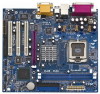
1.4 Motherboard Layout 12 34 5 6 7 21.6cm (8.5 in) PS/2 Mouse PS2_USB_PWR1 1 PS/2 Keyboard ...Ports Line out LiLInnineein MMIniicc in IR1 Super I/O AUDIO1 1 JR1 JL1 AUDIO CODEC Intel PCI 845GV LAN Chipset Clock Gen AGP1 PCI 1 775i45GV PCI 2 ` PCI 3 AMR1 FLOPPY1 2MB BIOS IDE2 IDE1 01 23 Intel ICH4 CMOS Battery CLRCMOS0 CHA_FAN1 USB45 1 1 SPEAKER1 1 PLED... / JL1 Jumpers 21 Front Panel Audio Connector (AUDIO1) 22 PCI Slots (PCI1- 3) 23 ASRock Graphics Interface Slot 24 Infrared Module Header (IR1) 25 Internal Audio Connector: CD1 (Black) 26 Internal Audio Connector: AUX1 (White)...
1.4 Motherboard Layout 12 34 5 6 7 21.6cm (8.5 in) PS/2 Mouse PS2_USB_PWR1 1 PS/2 Keyboard ...Ports Line out LiLInnineein MMIniicc in IR1 Super I/O AUDIO1 1 JR1 JL1 AUDIO CODEC Intel PCI 845GV LAN Chipset Clock Gen AGP1 PCI 1 775i45GV PCI 2 ` PCI 3 AMR1 FLOPPY1 2MB BIOS IDE2 IDE1 01 23 Intel ICH4 CMOS Battery CLRCMOS0 CHA_FAN1 USB45 1 1 SPEAKER1 1 PLED... / JL1 Jumpers 21 Front Panel Audio Connector (AUDIO1) 22 PCI Slots (PCI1- 3) 23 ASRock Graphics Interface Slot 24 Infrared Module Header (IR1) 25 Internal Audio Connector: CD1 (Black) 26 Internal Audio Connector: AUX1 (White)...

User Manual
Page 11
...not over-tighten the screws! To avoid damaging the motherboard components due to static electricity, NEVER place your chassis to the motherboard, peripherals, and/or components. 11 Whenever you handle components. 3. Chapter 2 Installation 775i45GV is detached from the wall socket before touching any component.... 2. Failure to do so may cause physical injuries to you install or remove any component, ensure that the motherboard fits into the holes indicated by...
...not over-tighten the screws! To avoid damaging the motherboard components due to static electricity, NEVER place your chassis to the motherboard, peripherals, and/or components. 11 Whenever you handle components. 3. Chapter 2 Installation 775i45GV is detached from the wall socket before touching any component.... 2. Failure to do so may cause physical injuries to you install or remove any component, ensure that the motherboard fits into the holes indicated by...

User Manual
Page 14
... with fan operation or contact other . Step 5. Connect fan header with Intel 775-Pin CPU to the CPU fan connector on the motherboard. Please adopt the type of heatsink and cooling fan compliant with the CPU fan connector on fastener caps with each other components. 14... 6. Apply thermal interface material onto center of your CPU fan and heatsink. Before you installed the heatsink, you press down on the motherboard. Ensure that supports Intel 775-Pin CPU. Step 1. Rotate the fastener clockwise, then press down the fasteners without rotating them clockwise, the...
... with fan operation or contact other . Step 5. Connect fan header with Intel 775-Pin CPU to the CPU fan connector on the motherboard. Please adopt the type of heatsink and cooling fan compliant with the CPU fan connector on fastener caps with each other components. 14... 6. Apply thermal interface material onto center of your CPU fan and heatsink. Before you installed the heatsink, you press down on the motherboard. Ensure that supports Intel 775-Pin CPU. Step 1. Rotate the fastener clockwise, then press down the fasteners without rotating them clockwise, the...

User Manual
Page 15
... the DIMM if you force the DIMM into the slot until the retaining clips at incorrect orientation. 2.5 Installation of Memory Modules (DIMM) 775i45GV motherboard provides two 184-pin DDR (Double Data Rate) DIMM slots. Step 1. Firmly insert the DIMM into the slot at both ends fully snap back in ...
... the DIMM if you force the DIMM into the slot until the retaining clips at incorrect orientation. 2.5 Installation of Memory Modules (DIMM) 775i45GV motherboard provides two 184-pin DDR (Double Data Rate) DIMM slots. Step 1. Firmly insert the DIMM into the slot at both ends fully snap back in ...

User Manual
Page 16
... the expansion card and make necessary hardware settings for the card before you intend to use . Remove the system unit cover (if your motherboard is unplugged. Step 3. Align the card connector with the PCI card installed in a chassis). Because the installed AMR card will automatically set...Easy Dual Monitor Installing an expansion card Step 1. Step 6. If the onboard VGA driver has already been installed before you need to insert an ASRock MR card (optional) with screws. AMR slot: AMR slot is a special design that you start the installation. Remove the bracket facing the ...
... the expansion card and make necessary hardware settings for the card before you intend to use . Remove the system unit cover (if your motherboard is unplugged. Step 3. Align the card connector with the PCI card installed in a chassis). Because the installed AMR card will automatically set...Easy Dual Monitor Installing an expansion card Step 1. Step 6. If the onboard VGA driver has already been installed before you need to insert an ASRock MR card (optional) with screws. AMR slot: AMR slot is a special design that you start the installation. Remove the bracket facing the ...

User Manual
Page 17
... Monitor feature. The data in the Support CD: ..\ Easy Dual Monitor 2.8 Jumpers Setup The illustration shows how jumpers are setup. Please remember to ASRock patented AGI8X Technology, this motherboard supports Easy Dual Monitor upgrade. For the detailed instruction, please refer to clear the data in CMOS. If no jumper cap is placed...
... Monitor feature. The data in the Support CD: ..\ Easy Dual Monitor 2.8 Jumpers Setup The illustration shows how jumpers are setup. Please remember to ASRock patented AGI8X Technology, this motherboard supports Easy Dual Monitor upgrade. For the detailed instruction, please refer to clear the data in CMOS. If no jumper cap is placed...

User Manual
Page 18
Placing jumper caps over these headers and connectors. Connector FDD Connector (33-pin FLOPPY1) (see p.9, No. 12) USB_PWR P-5 P+5 GND DUMMY 1 GND P+4 P-4 USB_PWR ASRock I /O panel are NOT jumpers. Primary IDE Connector (Blue) Secondary IDE Connector (Black) (39-pin IDE1, see p.9, No. 8) (39-pin IDE2, see p.9, ...No. 9) PIN1 IDE1 PIN1 IDE2 connect the blue end to the motherboard connect the black end to the IDE devices 80-conductor ATA 66/100 cable Note: If you to support 2 additional USB 2.0 ports. If those USB...
Placing jumper caps over these headers and connectors. Connector FDD Connector (33-pin FLOPPY1) (see p.9, No. 12) USB_PWR P-5 P+5 GND DUMMY 1 GND P+4 P-4 USB_PWR ASRock I /O panel are NOT jumpers. Primary IDE Connector (Blue) Secondary IDE Connector (Black) (39-pin IDE1, see p.9, No. 8) (39-pin IDE2, see p.9, ...No. 9) PIN1 IDE1 PIN1 IDE2 connect the blue end to the motherboard connect the black end to the IDE devices 80-conductor ATA 66/100 cable Note: If you to support 2 additional USB 2.0 ports. If those USB...

User Manual
Page 20
... you wish to enter the BIOS Setup after POST, restart the system by pressing + + , or by turning the system off and then back on the motherboard stores the BIOS Setup Utility.
... you wish to enter the BIOS Setup after POST, restart the system by pressing + + , or by turning the system off and then back on the motherboard stores the BIOS Setup Utility.

User Manual
Page 24
...to reduce the risks of LGA 775 CPU in the motherboard's Support CD through the following path: ..\ MPEGAV \ AVSEQ01.DAT To see this chapter for further information. 24 Since it . 4.2.4 ASRock PC-DIY Live Demo Program ASRock presents you a multimedia PC-DIY live demo program before... you how to play the file. 4.2.5 "LGA 775 CPU Installation Live Demo" Program This motherboard is equipped with the motherboard contains necessary drivers and useful utilities ...
...to reduce the risks of LGA 775 CPU in the motherboard's Support CD through the following path: ..\ MPEGAV \ AVSEQ01.DAT To see this chapter for further information. 24 Since it . 4.2.4 ASRock PC-DIY Live Demo Program ASRock presents you a multimedia PC-DIY live demo program before... you how to play the file. 4.2.5 "LGA 775 CPU Installation Live Demo" Program This motherboard is equipped with the motherboard contains necessary drivers and useful utilities ...

User Manual
Page 25
...Selection: CPU Ratio is determined by the installed processor. Set to enable or disable the feature of the installed motherboard. Chipset Configuration Resource Configuration Peripheral Configuration System Hardware Monitor F1:Help Esc:Exit :Select Item :Select Menu +/-:Change... supports Hyper-Threading technology and an operating system that includes optimization for better system stability. SDRAM Frequency: If [Auto] is selected, the motherboard will introduce you the following BIOS Setup menus: "Advanced," "Security," "Power," "Boot," and "Exit." 1. This option will equal ...
...Selection: CPU Ratio is determined by the installed processor. Set to enable or disable the feature of the installed motherboard. Chipset Configuration Resource Configuration Peripheral Configuration System Hardware Monitor F1:Help Esc:Exit :Select Item :Select Menu +/-:Change... supports Hyper-Threading technology and an operating system that includes optimization for better system stability. SDRAM Frequency: If [Auto] is selected, the motherboard will introduce you the following BIOS Setup menus: "Advanced," "Security," "Power," "Boot," and "Exit." 1. This option will equal ...

User Manual
Page 28
... primary IDE channel or the secondary IDE channel. If this onboard infrared port feature. OnBoard MC'97 Modem: Select [Auto] or [Disabled] for CPU temperature, Motherboard temperature, CPU fan speed, and critical voltage. 28 OnBoard Midi Port: Select address for this option is [ECP+EPP]. System Hardware Monitor: You can check...
... primary IDE channel or the secondary IDE channel. If this onboard infrared port feature. OnBoard MC'97 Modem: Select [Auto] or [Disabled] for CPU temperature, Motherboard temperature, CPU fan speed, and critical voltage. 28 OnBoard Midi Port: Select address for this option is [ECP+EPP]. System Hardware Monitor: You can check...

