User Manual
Page 3
... 64-bit With RAID Functions 22 2.12 Installing Windows 98 / ME / 2000 / XP / XP 64-bit Without RAID Functions 23 3. Contents 1. Introduction 5 1.1 Package Contents 5 1.2 Specifications 6 1.3 Motherboard Layout 9 1.4 ASRock I/O Plus 10 TM 2.
... 64-bit With RAID Functions 22 2.12 Installing Windows 98 / ME / 2000 / XP / XP 64-bit Without RAID Functions 23 3. Contents 1. Introduction 5 1.1 Package Contents 5 1.2 Specifications 6 1.3 Motherboard Layout 9 1.4 ASRock I/O Plus 10 TM 2.
User Manual
Page 5
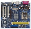
... Installation Live Demo) One 80-conductor Ultra ATA 66/100/133 IDE Ribbon Cable One Ribbon Cable for purchasing ASRock 775VM800Pro-DDR2 motherboard, a reliable motherboard produced under ASRock's consistently stringent quality control. ASRock website http://www.asrock.com 1.1 Package Contents ASRock 775VM800Pro-DDR2 Motherboard (Micro ATX Form Factor: 9.6-in x 8.5-in Floppy Drive One Serial ATA (SATA) Cable One Serial ATA (SATA) HDD...
... Installation Live Demo) One 80-conductor Ultra ATA 66/100/133 IDE Ribbon Cable One Ribbon Cable for purchasing ASRock 775VM800Pro-DDR2 motherboard, a reliable motherboard produced under ASRock's consistently stringent quality control. ASRock website http://www.asrock.com 1.1 Package Contents ASRock 775VM800Pro-DDR2 Motherboard (Micro ATX Form Factor: 9.6-in x 8.5-in Floppy Drive One Serial ATA (SATA) Cable One Serial ATA (SATA) HDD...

User Manual
Page 8
...it is detected, the system will automatically shutdown. It may cause the instability of the system or damage the CPU. 3. Although this motherboard! It may not work properly under Microsoft® Windows® XP SP1 / 2000 SP4. While CPU overheat is not recommended to ... AGP slot of "Hyper Threading Technology", please check page 27. 2. Before you install the PC system. 4. About the setting of this motherboard offers stepless control, it back again. CAUTION! 1. To improve heat dissipation, remember to perform over-clocking. Frequencies other than the recommended CPU...
...it is detected, the system will automatically shutdown. It may cause the instability of the system or damage the CPU. 3. Although this motherboard! It may not work properly under Microsoft® Windows® XP SP1 / 2000 SP4. While CPU overheat is not recommended to ... AGP slot of "Hyper Threading Technology", please check page 27. 2. Before you install the PC system. 4. About the setting of this motherboard offers stepless control, it back again. CAUTION! 1. To improve heat dissipation, remember to perform over-clocking. Frequencies other than the recommended CPU...

User Manual
Page 9
...PCI Slots (PCI1- 3) 26 Flash Memory 27 Serial Port Connector (COM1) 28 Infrared Module Header (IR1) 29 Shared USB 2.0 Header (USB4_5, Blue) 9 1.3 Motherboard Layout 1 234 PS2 Mouse PS2_US1 B_PWR1 ATX12V1 5 6 7 21.6cm (8.5 in) 24.4cm (9.6 in) Dual Core CPU DDRII_1 (64/72 bit, 240-pin ...IR1 ATXPWR1 VIA P4M800 Pro Chipset AGP 8X FSB1066 Super I/O LAN PHY 4Mb BIOS AUX1 Audio CODEC CD1 1 AUDIO1 JR1 JL1 1.5V_AGP1 PCI 1 775VM800Pro-DDR2 PCI 2 USB2.0 PCI 3 5.1CH AMR1 FLOPPY1 CLRCMOS1 CMOS Battery VIA VT8237R Plus 1 USB67 1 PANEL 1 SPEAKER1 PLED PWRBTN 1 HDLED RESET ...
...PCI Slots (PCI1- 3) 26 Flash Memory 27 Serial Port Connector (COM1) 28 Infrared Module Header (IR1) 29 Shared USB 2.0 Header (USB4_5, Blue) 9 1.3 Motherboard Layout 1 234 PS2 Mouse PS2_US1 B_PWR1 ATX12V1 5 6 7 21.6cm (8.5 in) 24.4cm (9.6 in) Dual Core CPU DDRII_1 (64/72 bit, 240-pin ...IR1 ATXPWR1 VIA P4M800 Pro Chipset AGP 8X FSB1066 Super I/O LAN PHY 4Mb BIOS AUX1 Audio CODEC CD1 1 AUDIO1 JR1 JL1 1.5V_AGP1 PCI 1 775VM800Pro-DDR2 PCI 2 USB2.0 PCI 3 5.1CH AMR1 FLOPPY1 CLRCMOS1 CMOS Battery VIA VT8237R Plus 1 USB67 1 PANEL 1 SPEAKER1 PLED PWRBTN 1 HDLED RESET ...

User Manual
Page 11
... power cord is a Micro ATX form factor (9.6" x 8.5", 24.4 x 21.6 cm) motherboard. Before you uninstall any component, place it . Before you install motherboard components or change any motherboard settings. 1. Make sure to static electricity, NEVER place your chassis to ensure that the... to use a grounded wrist strap or touch a safety grounded object before you and damages to the motherboard, peripherals, and/or components. 11 Chapter 2 Installation 775VM800Pro-DDR2 is detached from the wall socket before touching any component. 2. Unplug the power cord from the power...
... power cord is a Micro ATX form factor (9.6" x 8.5", 24.4 x 21.6 cm) motherboard. Before you uninstall any component, place it . Before you install motherboard components or change any motherboard settings. 1. Make sure to static electricity, NEVER place your chassis to ensure that the... to use a grounded wrist strap or touch a safety grounded object before you and damages to the motherboard, peripherals, and/or components. 11 Chapter 2 Installation 775VM800Pro-DDR2 is detached from the wall socket before touching any component. 2. Unplug the power cord from the power...

User Manual
Page 13
... the orient keys. Step 2-4. While pressing down lightly on center of PnP cap to assist in removal. 1. This cap must be placed if returning the motherboard for after service. Step 4. Step 4-2. Close the socket: Step 4-1. For proper inserting, please ensure to match the two orientation key notches of the CPU with...
... the orient keys. Step 2-4. While pressing down lightly on center of PnP cap to assist in removal. 1. This cap must be placed if returning the motherboard for after service. Step 4. Step 4-2. Close the socket: Step 4-1. For proper inserting, please ensure to match the two orientation key notches of the CPU with...

User Manual
Page 14
... cannot be secured on the socket surface. Secure excess cable with 775-Pin socket that the CPU and the heatsink are oriented on the motherboard (CPU_FAN1, see page 9, No. 3). For proper installation, please kindly refer to the instruction manuals of IHS on the... center of your CPU fan and heatsink. Step 3. 2.4 Installation of CPU Fan and Heatsink This motherboard is an example to illustrate the installation of the heatsink for 775-LAND CPU. Repeat with the motherboard throughholes. Connect fan header with the CPU fan connector on fastener caps with fan operation or contact...
... cannot be secured on the socket surface. Secure excess cable with 775-Pin socket that the CPU and the heatsink are oriented on the motherboard (CPU_FAN1, see page 9, No. 3). For proper installation, please kindly refer to the instruction manuals of IHS on the... center of your CPU fan and heatsink. Step 3. 2.4 Installation of CPU Fan and Heatsink This motherboard is an example to illustrate the installation of the heatsink for 775-LAND CPU. Repeat with the motherboard throughholes. Connect fan header with the CPU fan connector on fastener caps with fan operation or contact...

User Manual
Page 15
... 3. Align a DIMM on the slot such that the notch on the DIMM matches the break on the slot. 2.5 Installation of Memory Modules (DIMM) 775VM800Pro-DDR2 motherboard provides two 240-pin DDRII (Double Data Rate) DIMM slots. It will cause permanent damage to disconnect power supply before adding or removing DIMMs or... the system components. Step 2. Please make sure to the motherboard and the DIMM if you force the DIMM into DDRII slot; Unlock a DIMM slot by pressing the retaining clips outward.
... 3. Align a DIMM on the slot such that the notch on the DIMM matches the break on the slot. 2.5 Installation of Memory Modules (DIMM) 775VM800Pro-DDR2 motherboard provides two 240-pin DDRII (Double Data Rate) DIMM slots. It will cause permanent damage to disconnect power supply before adding or removing DIMMs or... the system components. Step 2. Please make sure to the motherboard and the DIMM if you force the DIMM into DDRII slot; Unlock a DIMM slot by pressing the retaining clips outward.

User Manual
Page 16
... with the slot and press firmly until the card is used to insert an ASRock MR card with screws. PCI slots: PCI slots are 3 PCI slots, 1 AMR slot, and 1 AGP slot on the AGP slot of your motherboard is already installed in a chassis). AGP slot: The AGP slot is unplugged. Please read... 32-bit PCI interface. Please do NOT use . Before installing the expansion card, please make necessary hardware settings for later use a 3.3V AGP card on 775VM800Pro-DDR2 motherboard. Step 3.
... with the slot and press firmly until the card is used to insert an ASRock MR card with screws. PCI slots: PCI slots are 3 PCI slots, 1 AMR slot, and 1 AGP slot on the AGP slot of your motherboard is already installed in a chassis). AGP slot: The AGP slot is unplugged. Please read... 32-bit PCI interface. Please do NOT use . Before installing the expansion card, please make necessary hardware settings for later use a 3.3V AGP card on 775VM800Pro-DDR2 motherboard. Step 3.

User Manual
Page 18
...interface allows up to the IDE devices 80-conductor ATA 66/100/133 cable Note: If you use only one IDE device on the motherboard. 18 2.8 Onboard Headers and Connectors Onboard headers and connectors are NOT jumpers. Besides, to optimize compatibility and performance, please connect your... to the secondary IDE connector (IDE2, black). Placing jumper caps over these headers and connectors. Serial ATA (SATA) Data Cable Either end of the motherboard! Serial ATA Connectors (SATA1: see p.9, No. 14) (SATA2: see p.9, No. 19) Pin1 FLOPPY1 the red-striped side to the SATA hard...
...interface allows up to the IDE devices 80-conductor ATA 66/100/133 cable Note: If you use only one IDE device on the motherboard. 18 2.8 Onboard Headers and Connectors Onboard headers and connectors are NOT jumpers. Besides, to optimize compatibility and performance, please connect your... to the secondary IDE connector (IDE2, black). Placing jumper caps over these headers and connectors. Serial ATA (SATA) Data Cable Either end of the motherboard! Serial ATA Connectors (SATA1: see p.9, No. 14) (SATA2: see p.9, No. 19) Pin1 FLOPPY1 the red-striped side to the SATA hard...

User Manual
Page 21
... the OS has been installed into the drive bays of your chassis. What is Hot Plug Function? 2.9 Serial ATA (SATA) Hard Disks Installation This motherboard adopts VIA VT8237R Plus southbridge chipset that it is called "Hot Plug" for SATA Devices. STEP 2: Connect the SATA power cable to install the SATA.... STEP 3: Connect one end of the SATA data cable to the SATA hard disk. 2.10 Hot Plug and Hot Swap Functions for SATA HDDs 775VM800Pro-DDR2 motherboard supports Hot Plug and Hot Swap functions for the action to insert and remove the SATA HDDs while the system is called "Hot Swap" for...
... the OS has been installed into the drive bays of your chassis. What is Hot Plug Function? 2.9 Serial ATA (SATA) Hard Disks Installation This motherboard adopts VIA VT8237R Plus southbridge chipset that it is called "Hot Plug" for SATA Devices. STEP 2: Connect the SATA power cable to install the SATA.... STEP 3: Connect one end of the SATA data cable to the SATA hard disk. 2.10 Hot Plug and Hot Swap Functions for SATA HDDs 775VM800Pro-DDR2 motherboard supports Hot Plug and Hot Swap functions for the action to insert and remove the SATA HDDs while the system is called "Hot Swap" for...

User Manual
Page 24
... device to enter the BIOS SETUP UTILITY after POST, restart the system by pressing + + , or by turning the system off and then back on the motherboard stores the BIOS SETUP UTILITY. You may not exactly match what you wish to locate and load the Operating System Security To set up the...
... device to enter the BIOS SETUP UTILITY after POST, restart the system by pressing + + , or by turning the system off and then back on the motherboard stores the BIOS SETUP UTILITY. You may not exactly match what you wish to locate and load the Operating System Security To set up the...
User Manual
Page 26
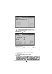
Setting wrong values in this motherboard is "Locked" or "Unlocked". CPU Thermal Throttling No-Excute Memory Protection Enhance Halt State Hyper Threading Technology Intel (R) SpeedStep(tm) tech. [Auto] [200] [Enabled] [Auto] : ... Guard Spread Spectrum Ratio Status Ratio Actual Value Max CPUID Value Limit 'Intel (R) Virtualization tech. Boot Failure Guard Enable or disable the feature of this motherboard. Ratio Status This is a read-only item, which displays whether the ratio status of this...
Setting wrong values in this motherboard is "Locked" or "Unlocked". CPU Thermal Throttling No-Excute Memory Protection Enhance Halt State Hyper Threading Technology Intel (R) SpeedStep(tm) tech. [Auto] [200] [Enabled] [Auto] : ... Guard Spread Spectrum Ratio Status Ratio Actual Value Max CPUID Value Limit 'Intel (R) Virtualization tech. Boot Failure Guard Enable or disable the feature of this motherboard. Ratio Status This is a read-only item, which displays whether the ratio status of this...
User Manual
Page 27
... the CPU from the chipset. The C1 state is an enhancement to the core speed of the installed processor. Hyper Threading Technology To enable this motherboard. Intel (R) SpeedStep(tm) tech. is a read-only item, which displays the ratio actual value of the system caches. Enhance Halt State All processors support the...
... the CPU from the chipset. The C1 state is an enhancement to the core speed of the installed processor. Hyper Threading Technology To enable this motherboard. Intel (R) SpeedStep(tm) tech. is a read-only item, which displays the ratio actual value of the system caches. Enhance Halt State All processors support the...

User Manual
Page 28
... memory module(s) inserted and assigns appropriate frequency automatically. The default value is set the timing by dram SPD. DRAM Frequency If [Auto] is selected, the motherboard will allow better tolerance for memory compatibility when it is set to [Auto] to set to select DRAM Bank Interleave.
... memory module(s) inserted and assigns appropriate frequency automatically. The default value is set the timing by dram SPD. DRAM Frequency If [Auto] is selected, the motherboard will allow better tolerance for memory compatibility when it is set to [Auto] to set to select DRAM Bank Interleave.
User Manual
Page 30
... AGP fast write protocol support. OnBoard LAN This allows you to speed up the V-Link speed. If you install an 8X-AGP card on this motherboard, you to select IDE read prefetch buffer. AGP GADSTB Output Delay Use this option to [Auto]. V-Link Speed This feature allows you may set the...
... AGP fast write protocol support. OnBoard LAN This allows you to speed up the V-Link speed. If you install an 8X-AGP card on this motherboard, you to select IDE read prefetch buffer. AGP GADSTB Output Delay Use this option to [Auto]. V-Link Speed This feature allows you may set the...

User Manual
Page 38
... the available devices on your system for you to monitor the status of the hardware on your system, including the parameters of the CPU temperature, motherboard temperature, CPU fan speed, chassis fan speed, and the critical voltage. Main Advanced BIOS SETUP UTILITY H/W Monitor Boot Security Exit Boot Settings Boot Settings Configuration...
... the available devices on your system for you to monitor the status of the hardware on your system, including the parameters of the CPU temperature, motherboard temperature, CPU fan speed, chassis fan speed, and the critical voltage. Main Advanced BIOS SETUP UTILITY H/W Monitor Boot Security Exit Boot Settings Boot Settings Configuration...

User Manual
Page 42
...CD into your OS documentation for more about ASRock, welcome to reduce the risks of CPU and motherboard damages caused by improper handling, ASRock sincerely presents you start the installation of LGA 775 CPU in order to visit ASRock's website at http://www.asrock.com; Since it . 4.2.4 "LGA 775 ...CPU Installation Live Demo" Program This motherboard is a new CPU socket interface that Intel has released. You may contact your computer. 4. Click on ...
...CD into your OS documentation for more about ASRock, welcome to reduce the risks of CPU and motherboard damages caused by improper handling, ASRock sincerely presents you start the installation of LGA 775 CPU in order to visit ASRock's website at http://www.asrock.com; Since it . 4.2.4 "LGA 775 ...CPU Installation Live Demo" Program This motherboard is a new CPU socket interface that Intel has released. You may contact your computer. 4. Click on ...

