User Manual
Page 3
...-bit Without RAID Functions 23 3. Contents 1. Introduction 5 1.1 Package Contents 5 1.2 Specifications 6 1.3 Motherboard Layout 8 1.4 ASRock I/O Plus 9 TM 2. BIOS SETUP UTILITY 24 3.1 Introduction 24 3.1.1 BIOS Menu Bar 24 3.1.2 Navigation Keys 25 3.2 Main Screen 25 3.3 Advanced Screen 25... 3.3.1 CPU Configuration 26 3.3.2 Chipset Configuration 27 3.3.3 ACPI Configuration 29 3.3.4 IDE Configuration 30 3.3.5 PCIPnP Configuration 32 3.3.6 Floppy Configuration 32...
...-bit Without RAID Functions 23 3. Contents 1. Introduction 5 1.1 Package Contents 5 1.2 Specifications 6 1.3 Motherboard Layout 8 1.4 ASRock I/O Plus 9 TM 2. BIOS SETUP UTILITY 24 3.1 Introduction 24 3.1.1 BIOS Menu Bar 24 3.1.2 Navigation Keys 25 3.2 Main Screen 25 3.3 Advanced Screen 25... 3.3.1 CPU Configuration 26 3.3.2 Chipset Configuration 27 3.3.3 ACPI Configuration 29 3.3.4 IDE Configuration 30 3.3.5 PCIPnP Configuration 32 3.3.6 Floppy Configuration 32...

User Manual
Page 4
4. Software Support 39 4.1 Install Operating System 39 4.2 Support CD Information 39 4.2.1 Running Support CD 39 4.2.2 Drivers Menu 39 4.2.3 Utilities Menu 39 4.2.4 "LGA 775 CPU Installation Live Demo" Program.... 39 4.2.5 Contact Information 39 4
4. Software Support 39 4.1 Install Operating System 39 4.2 Support CD Information 39 4.2.1 Running Support CD 39 4.2.2 Drivers Menu 39 4.2.3 Utilities Menu 39 4.2.4 "LGA 775 CPU Installation Live Demo" Program.... 39 4.2.5 Contact Information 39 4

User Manual
Page 5
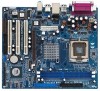
... be updated, the content of this manual occur, the updated version will be available on ASRock website as well. ASRock website http://www.asrock.com 1.1 Package Contents ASRock 775VM800 Motherboard (Micro ATX Form Factor: 9.6-in x 8.2-in Floppy Drive One Serial ATA (SATA...delivers excellent performance with robust design conforming to ASRock's commitment to the hardware installation. Introduction Thank you for a 3.5-in , 24.4 cm x 20.8 cm) ASRock 775VM800 Quick Installation Guide ASRock 775VM800 Support CD (including LGA 775 CPU Installation Live Demo) One 80-conductor Ultra ATA...
... be updated, the content of this manual occur, the updated version will be available on ASRock website as well. ASRock website http://www.asrock.com 1.1 Package Contents ASRock 775VM800 Motherboard (Micro ATX Form Factor: 9.6-in x 8.2-in Floppy Drive One Serial ATA (SATA...delivers excellent performance with robust design conforming to ASRock's commitment to the hardware installation. Introduction Thank you for a 3.5-in , 24.4 cm x 20.8 cm) ASRock 775VM800 Quick Installation Guide ASRock 775VM800 Support CD (including LGA 775 CPU Installation Live Demo) One 80-conductor Ultra ATA...
User Manual
Page 7
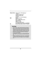
... Line In / Line Out / Microphone BIOS: AMI BIOS Supports "Plug and Play" ACPI 1.1 compliance wake up events Supports jumperfree SMBIOS 2.3.1 support CPU frequency stepless control (only for USB 2.0 works fine under Microsoft® Windows® 98 / ME. 5. It may cause permanent damage! 4.... users' reference, see CAUTION 5) OS: Microsoft® Windows® 98SE / ME / 2000 / XP compliant CAUTION! 1. Before you install the PC system. 3. ASRock I/O PlusTM: 1 PS/2 mouse port, 1 PS/2 keyboard port, 1 VGA port, 1 parallel port: ECP/EPP support, 6 ready-to-use a 3.3V AGP card...
... Line In / Line Out / Microphone BIOS: AMI BIOS Supports "Plug and Play" ACPI 1.1 compliance wake up events Supports jumperfree SMBIOS 2.3.1 support CPU frequency stepless control (only for USB 2.0 works fine under Microsoft® Windows® 98 / ME. 5. It may cause permanent damage! 4.... users' reference, see CAUTION 5) OS: Microsoft® Windows® 98SE / ME / 2000 / XP compliant CAUTION! 1. Before you install the PC system. 3. ASRock I/O PlusTM: 1 PS/2 mouse port, 1 PS/2 keyboard port, 1 VGA port, 1 parallel port: ECP/EPP support, 6 ready-to-use a 3.3V AGP card...
User Manual
Page 8
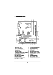
... IR1 USB4_5 ATXPWR1 VIA P4M800 Chipset AGP 8X IDE2 Super I/O LAN PHY 4Mb BIOS AUX1 CD1 Audio CODEC 1 AUDIO1 JR1 JL1 1.5V_AGP1 PCI 1 ` 775VM800 PCI 2 USB2.0 PCI 3 5.1CH FLOPPY1 AMR1 CLRCMOS1 CMOS Battery VIA VT8237R 1 USB67 PANEL 1 PLED PWRBTN 1 1 SPEAKER1 HDLED RESET SATA2 IDE1 SATA ...17 16 15 14 13 1 PS2_USB_PWR1 Jumper 2 ATX 12V Connector (ATX12V1) 3 ATX Power Connector (ATXPWR1) 4 Chassis Fan Connector (CHA_FAN1) 5 775-Pin CPU Socket 6 North Bridge Controller 7 2 x 184-pin DDR DIMM Slots (DDR1, DDR2; Blue) 8 Secondary IDE Connector (IDE2, Black) 9 Primary IDE Connector...
... IR1 USB4_5 ATXPWR1 VIA P4M800 Chipset AGP 8X IDE2 Super I/O LAN PHY 4Mb BIOS AUX1 CD1 Audio CODEC 1 AUDIO1 JR1 JL1 1.5V_AGP1 PCI 1 ` 775VM800 PCI 2 USB2.0 PCI 3 5.1CH FLOPPY1 AMR1 CLRCMOS1 CMOS Battery VIA VT8237R 1 USB67 PANEL 1 PLED PWRBTN 1 1 SPEAKER1 HDLED RESET SATA2 IDE1 SATA ...17 16 15 14 13 1 PS2_USB_PWR1 Jumper 2 ATX 12V Connector (ATX12V1) 3 ATX Power Connector (ATXPWR1) 4 Chassis Fan Connector (CHA_FAN1) 5 775-Pin CPU Socket 6 North Bridge Controller 7 2 x 184-pin DDR DIMM Slots (DDR1, DDR2; Blue) 8 Secondary IDE Connector (IDE2, Black) 9 Primary IDE Connector...

User Manual
Page 11
...Pin1 orientation key notch orientation key notch Pin1 alignment key alignment key 775-LAND CPU 775-Pin Socket 11 black line black line Otherwise, the CPU will be seriously damaged. Step 2. Orient the CPU with black lines. Rotate the load plate to fully open position at approximately 135... degrees. Locate Pin1 and the two orientation key notches. Step 1-3. Hold the CPU by depressing down and out on the socket. 2.3 CPU Installation For the installation of Intel 775-LAND CPU, please follow the steps below. 775-Pin Socket Overview Before you insert the 775-...
...Pin1 orientation key notch orientation key notch Pin1 alignment key alignment key 775-LAND CPU 775-Pin Socket 11 black line black line Otherwise, the CPU will be seriously damaged. Step 2. Orient the CPU with black lines. Rotate the load plate to fully open position at approximately 135... degrees. Locate Pin1 and the two orientation key notches. Step 1-3. Hold the CPU by depressing down and out on the socket. 2.3 CPU Installation For the installation of Intel 775-LAND CPU, please follow the steps below. 775-Pin Socket Overview Before you insert the 775-...

User Manual
Page 12
Verify that the CPU is recommended to use the cap tab to handle and avoid kicking off the PnP cap. Step 4. Rotate the load plate onto the IHS. It ... down lightly on center of PnP cap to assist in removal. For proper inserting, please ensure to match the two orientation key notches of the CPU with the two alignment keys of load lever. 12 Step 2-3. Carefully place the...
Verify that the CPU is recommended to use the cap tab to handle and avoid kicking off the PnP cap. Step 4. Rotate the load plate onto the IHS. It ... down lightly on center of PnP cap to assist in removal. For proper inserting, please ensure to match the two orientation key notches of the CPU with the two alignment keys of load lever. 12 Step 2-3. Carefully place the...

User Manual
Page 13
...the motherboard throughholes. Below is equipped with each other components. 13 Step 1. Apply thermal interface material onto center of CPU Fan and Heatsink This motherboard is an example to the CPU fan connector on the motherboard (CPU_FAN1, see page 8, No. 29). If you need to spray thermal interface ... press down on the motherboard. Secure excess cable with tie-wrap to ensure cable does not interfere with Intel 775-LAND CPU to improve heat dissipation. Please adopt the type of heatsink and cooling fan compliant with fan operation or contact other . Step 6.
...the motherboard throughholes. Below is equipped with each other components. 13 Step 1. Apply thermal interface material onto center of CPU Fan and Heatsink This motherboard is an example to the CPU fan connector on the motherboard (CPU_FAN1, see page 8, No. 29). If you need to spray thermal interface ... press down on the motherboard. Secure excess cable with tie-wrap to ensure cable does not interfere with Intel 775-LAND CPU to improve heat dissipation. Please adopt the type of heatsink and cooling fan compliant with fan operation or contact other . Step 6.

User Manual
Page 19
... cable to this connector and match the black wire to this connector. Please install the heatsink and the CPU fan before installing ATX 12V connector; Please connect the chassis speaker to the ground pin. otherwise, it can provides sufficient power....GND HDLEDHDLED+ 1 SPEAKER DUMMY DUMMY +5V This header accommodates several system front panel functions. Chassis Fan Connector (3-pin CHA_FAN1) (see p.8, No. 4) GND +12V CHA_FAN_SPEED CPU Fan Connector (4-pin CPU_FAN1) (see p.8, No. 29) N/C CPU_FAN_SPEED +12V GND ATX Power Connector (20-pin ATXPWR1) (see p.8, No. 2) Please note that it...
... cable to this connector and match the black wire to this connector. Please install the heatsink and the CPU fan before installing ATX 12V connector; Please connect the chassis speaker to the ground pin. otherwise, it can provides sufficient power....GND HDLEDHDLED+ 1 SPEAKER DUMMY DUMMY +5V This header accommodates several system front panel functions. Chassis Fan Connector (3-pin CHA_FAN1) (see p.8, No. 4) GND +12V CHA_FAN_SPEED CPU Fan Connector (4-pin CPU_FAN1) (see p.8, No. 29) N/C CPU_FAN_SPEED +12V GND ATX Power Connector (20-pin ATXPWR1) (see p.8, No. 2) Please note that it...
User Manual
Page 25
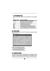
3.1.2 Navigation Keys Please check the following items: CPU Configuration, Chipset Configuration, ACPI Configuration, IDE Configuration, PCIPnP Configuration, Floppy Configuration, SuperIO Configuration, and USB Configuration. 25 System Date [Day Month/Date/Year...UTILITY Main Advanced H/W Monitor Boot Security Exit System Overview System Time System Date [17:00:09] [Wed 04/20/2005] BIOS Version : 775VM800 BIOS P1.00 Processor Type : Intel (R) CPU 3.20 GHz Processor Speed : 3200 MHz Cache Size : 1024KB Microcode Update : 0F34/0E Total Memory DIMM 1 DIMM 2 : 256MB with 64MB...
3.1.2 Navigation Keys Please check the following items: CPU Configuration, Chipset Configuration, ACPI Configuration, IDE Configuration, PCIPnP Configuration, Floppy Configuration, SuperIO Configuration, and USB Configuration. 25 System Date [Day Month/Date/Year...UTILITY Main Advanced H/W Monitor Boot Security Exit System Overview System Time System Date [17:00:09] [Wed 04/20/2005] BIOS Version : 775VM800 BIOS P1.00 Processor Type : Intel (R) CPU 3.20 GHz Processor Speed : 3200 MHz Cache Size : 1024KB Microcode Update : 0F34/0E Total Memory DIMM 1 DIMM 2 : 256MB with 64MB...
User Manual
Page 26
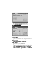
... changing the ratio value of this motherboard is a read-only item, which displays whether the ratio status of Boot Failure Guard. The actual CPU host frequency will find an item Ratio CMOS Setting appears to allow you will show in below sections may cause the system to malfunction...Help F9 Load Defaults F10 Save and Exit ESC Exit v02.54 (C) Copyright 1985-2003, American Megatrends, Inc. CPU Host Frequency While entering setup, BIOS auto detects the present CPU host frequency of this section may cause system to malfunction. Boot Failure Guard Enable or disable the feature of ...
... changing the ratio value of this motherboard is a read-only item, which displays whether the ratio status of Boot Failure Guard. The actual CPU host frequency will find an item Ratio CMOS Setting appears to allow you will show in below sections may cause the system to malfunction...Help F9 Load Defaults F10 Save and Exit ESC Exit v02.54 (C) Copyright 1985-2003, American Megatrends, Inc. CPU Host Frequency While entering setup, BIOS auto detects the present CPU host frequency of this section may cause system to malfunction. Boot Failure Guard Enable or disable the feature of ...

User Manual
Page 27
...a read-only item, which displays the ratio actual value of the installed processor. This option will be hidden if the current CPU does not support No-Excute Memory Protection. 3.3.2 Chipset Configuration BIOS SETUP UTILITY Advanced Chipset Configuration DRAM Frequency Flexibility Option DRAM CAS# ...Microsoft® Windows® XP, or Linux kernel version 2.4.18 or higher. This should be enabled in order to time the CPU frequency, it requires a computer system with an Intel Pentium®4 processor that supports Hyper-Threading technology and an operating system that cannot...
...a read-only item, which displays the ratio actual value of the installed processor. This option will be hidden if the current CPU does not support No-Excute Memory Protection. 3.3.2 Chipset Configuration BIOS SETUP UTILITY Advanced Chipset Configuration DRAM Frequency Flexibility Option DRAM CAS# ...Microsoft® Windows® XP, or Linux kernel version 2.4.18 or higher. This should be enabled in order to time the CPU frequency, it requires a computer system with an Intel Pentium®4 processor that supports Hyper-Threading technology and an operating system that cannot...
User Manual
Page 28
... PCI Delay Transaction feature will allow better tolerance for memory compatibility when it is set to [Auto]. It will free the PCI Bus when the CPU is [PCI]. DRAM CAS# Latency Use this feature when using ISA cards that are not PCI 2.1 compliant. 28 The default value of this feature is...
... PCI Delay Transaction feature will allow better tolerance for memory compatibility when it is set to [Auto]. It will free the PCI Bus when the CPU is [PCI]. DRAM CAS# Latency Use this feature when using ISA cards that are not PCI 2.1 compliant. 28 The default value of this feature is...
User Manual
Page 35
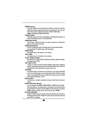
... section, it allows you to monitor the status of the hardware on your system, including the parameters of the CPU temperature, motherboard temperature, CPU fan speed, chassis fan speed, and the critical voltage. BIOS SETUP UTILITY Main Advanced H/W Monitor Boot Security Exit... Hardware Health Event Monitoring CPU Temperature M / B Temperature CPU Fan Speed Chassis Fan Speed Vcore + 3.30V + 5.00V + 12.00V : 37 C / 98 F : 31 C / 87 F : 2463 RPM : N/A : 1.629V : 3....
... section, it allows you to monitor the status of the hardware on your system, including the parameters of the CPU temperature, motherboard temperature, CPU fan speed, chassis fan speed, and the critical voltage. BIOS SETUP UTILITY Main Advanced H/W Monitor Boot Security Exit... Hardware Health Event Monitoring CPU Temperature M / B Temperature CPU Fan Speed Chassis Fan Speed Vcore + 3.30V + 5.00V + 12.00V : 37 C / 98 F : 31 C / 87 F : 2463 RPM : N/A : 1.629V : 3....
User Manual
Page 39
... on a specific item then follow the installation wizard to reduce the risks of CPU and motherboard damages caused by improper handling, ASRock sincerely presents you start the installation of LGA 775 CPU in order to install it. 4.2.4 "LGA 775 CPU Installation Live Demo" Program This motherboard is equipped with the motherboard contains necessary drivers...
... on a specific item then follow the installation wizard to reduce the risks of CPU and motherboard damages caused by improper handling, ASRock sincerely presents you start the installation of LGA 775 CPU in order to install it. 4.2.4 "LGA 775 CPU Installation Live Demo" Program This motherboard is equipped with the motherboard contains necessary drivers...


