User Manual
Page 3
... Memory Modules (DIMM 14 2.6 Expansion Slots (PCI, AMR, and AGP Slots 15 2.7 Jumpers Setup 16 2.8 Onboard Headers and Connectors 17 2.9 Serial ATA (SATA) Hard Disks Installation 20 2.10 Hot Plug and Hot Swap Functions for SATA HDDs .... 20 2.11 Installing Windows 2000 / XP / XP 64-bit With RAID Functions 21 2.12 Installing Windows 98 / ME / 2000 / XP / XP 64-bit Without RAID Functions 23 3. BIOS SETUP UTILITY 24 3.1 Introduction 24 3.1.1 BIOS Menu Bar 24 3.1.2 Navigation Keys 25 3.2 Main Screen 25 3.3 Advanced Screen 25 3.3.1 CPU Configuration 26 3.3.2 Chipset Configuration...
... Memory Modules (DIMM 14 2.6 Expansion Slots (PCI, AMR, and AGP Slots 15 2.7 Jumpers Setup 16 2.8 Onboard Headers and Connectors 17 2.9 Serial ATA (SATA) Hard Disks Installation 20 2.10 Hot Plug and Hot Swap Functions for SATA HDDs .... 20 2.11 Installing Windows 2000 / XP / XP 64-bit With RAID Functions 21 2.12 Installing Windows 98 / ME / 2000 / XP / XP 64-bit Without RAID Functions 23 3. BIOS SETUP UTILITY 24 3.1 Introduction 24 3.1.1 BIOS Menu Bar 24 3.1.2 Navigation Keys 25 3.2 Main Screen 25 3.3 Advanced Screen 25 3.3.1 CPU Configuration 26 3.3.2 Chipset Configuration...

User Manual
Page 5
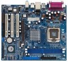
... ASRock 775VM800 Motherboard (Micro ATX Form Factor: 9.6-in x 8.2-in Floppy Drive One Serial ATA (SATA) Cable One Serial ATA (SATA) HDD Power Cable(Optional) One ASRock I/O PlusTM Shield One COM Port Bracket 5 Chapter 3 and 4 contain the configuration guide to quality and endurance. 1. In this manual occur, the updated version will be available on ASRock website as well. You may find the latest memory and CPU support lists on ASRock website without notice. Because the motherboard specifications and the BIOS software might be updated...
... ASRock 775VM800 Motherboard (Micro ATX Form Factor: 9.6-in x 8.2-in Floppy Drive One Serial ATA (SATA) Cable One Serial ATA (SATA) HDD Power Cable(Optional) One ASRock I/O PlusTM Shield One COM Port Bracket 5 Chapter 3 and 4 contain the configuration guide to quality and endurance. 1. In this manual occur, the updated version will be available on ASRock website as well. You may find the latest memory and CPU support lists on ASRock website without notice. Because the motherboard specifications and the BIOS software might be updated...
User Manual
Page 7
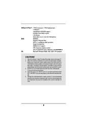
... port, 1 PS/2 keyboard port, 1 VGA port, 1 parallel port: ECP/EPP support, 6 ready-to-use a 3.3V AGP card on the motherboard functions properly and unplug the power cord, then plug it is detected, the system will automatically shutdown. Do NOT use USB 2.0 ports, 1 RJ 45 port, Audio Jack: Line In / Line Out / Microphone BIOS: AMI BIOS Supports "Plug and Play" ACPI 1.1 compliance wake up events Supports jumperfree SMBIOS 2.3.1 support CPU frequency stepless control (only for USB 2.0 works fine under Microsoft® Windows...
... port, 1 PS/2 keyboard port, 1 VGA port, 1 parallel port: ECP/EPP support, 6 ready-to-use a 3.3V AGP card on the motherboard functions properly and unplug the power cord, then plug it is detected, the system will automatically shutdown. Do NOT use USB 2.0 ports, 1 RJ 45 port, Audio Jack: Line In / Line Out / Microphone BIOS: AMI BIOS Supports "Plug and Play" ACPI 1.1 compliance wake up events Supports jumperfree SMBIOS 2.3.1 support CPU frequency stepless control (only for USB 2.0 works fine under Microsoft® Windows...
User Manual
Page 8
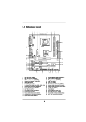
... 8X IDE2 Super I/O LAN PHY 4Mb BIOS AUX1 CD1 Audio CODEC 1 AUDIO1 JR1 JL1 1.5V_AGP1 PCI 1 ` 775VM800 PCI 2 USB2.0 PCI 3 5.1CH FLOPPY1 AMR1 CLRCMOS1 CMOS Battery VIA VT8237R 1 USB67 PANEL 1 PLED PWRBTN 1 1 SPEAKER1 HDLED RESET SATA2 IDE1 SATA SATA1 9 10 11 12 19 18 17 16 15 14 13 1 PS2_USB_PWR1 Jumper 2 ATX 12V Connector (ATX12V1) 3 ATX Power Connector (ATXPWR1) 4 Chassis Fan Connector (CHA_FAN1) 5 775-Pin CPU Socket 6 North Bridge Controller 7 2 x 184-pin DDR DIMM Slots (DDR1, DDR2;
... 8X IDE2 Super I/O LAN PHY 4Mb BIOS AUX1 CD1 Audio CODEC 1 AUDIO1 JR1 JL1 1.5V_AGP1 PCI 1 ` 775VM800 PCI 2 USB2.0 PCI 3 5.1CH FLOPPY1 AMR1 CLRCMOS1 CMOS Battery VIA VT8237R 1 USB67 PANEL 1 PLED PWRBTN 1 1 SPEAKER1 HDLED RESET SATA2 IDE1 SATA SATA1 9 10 11 12 19 18 17 16 15 14 13 1 PS2_USB_PWR1 Jumper 2 ATX 12V Connector (ATX12V1) 3 ATX Power Connector (ATXPWR1) 4 Chassis Fan Connector (CHA_FAN1) 5 775-Pin CPU Socket 6 North Bridge Controller 7 2 x 184-pin DDR DIMM Slots (DDR1, DDR2;
User Manual
Page 18
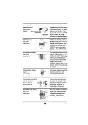
... ASRock I/O PlusTM provides you to receive stereo audio input from sound sources such as a CD-ROM, DVD-ROM, TV tuner card, or MPEG card. O U T- USB 2.0 Header (9-pin USB67) (see p.8, No. 23) AUX-R GND GND AUX-L CD-R GND GND CD-L AUX1 CD1 These connectors allow you 6 ready-to-use USB 2.0 ports on the drive. R MIC-POWER MIC This is available to support 2 extra USB 2.0 ports. Serial ATA (SATA) Power Cable (Optional) connect to the SATA HDD power connector connect to the power supply Please connect...
... ASRock I/O PlusTM provides you to receive stereo audio input from sound sources such as a CD-ROM, DVD-ROM, TV tuner card, or MPEG card. O U T- USB 2.0 Header (9-pin USB67) (see p.8, No. 23) AUX-R GND GND AUX-L CD-R GND GND CD-L AUX1 CD1 These connectors allow you 6 ready-to-use USB 2.0 ports on the drive. R MIC-POWER MIC This is available to support 2 extra USB 2.0 ports. Serial ATA (SATA) Power Cable (Optional) connect to the SATA HDD power connector connect to the power supply Please connect...

User Manual
Page 19
... cause the failure to the ground pin. Please connect the chassis speaker to this connector and match the black wire to this connector so that it may cause permanent damage! Please connect the CPU fan cable to this connector. otherwise, it can provides sufficient power. Please install the heatsink and the CPU fan before installing ATX 12V connector; ATX 12V Connector (4-pin ATX12V1) (see p.8, No. 3) Please connect the chassis fan cable to this header. Please connect an ATX power supply to this connector and...
... cause the failure to the ground pin. Please connect the chassis speaker to this connector and match the black wire to this connector so that it may cause permanent damage! Please connect the CPU fan cable to this connector. otherwise, it can provides sufficient power. Please install the heatsink and the CPU fan before installing ATX 12V connector; ATX 12V Connector (4-pin ATX12V1) (see p.8, No. 3) Please connect the chassis fan cable to this header. Please connect an ATX power supply to this connector and...
User Manual
Page 21
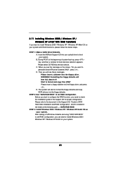
... the floppy drive, and press . WARNING! STEP 2: Use "SATA RAID BIOS" to set RAID configuration, you want to boot your system. 21 Please insert a floppy diskette into the floppy drive. Before you start to configure the RAID function, you will start to SATA Hard Disks Installation and RAID Configuration", which is located in it! E. A. Insert the ASRock Support CD into the floppy diskette. B. During POST at the following path: .. \ SATA RAID BIOS STEP 3: Install Windows 2000 / Windows XP / Windows XP 64-bit OS on the screen, "Do...
... the floppy drive, and press . WARNING! STEP 2: Use "SATA RAID BIOS" to set RAID configuration, you want to boot your system. 21 Please insert a floppy diskette into the floppy drive. Before you start to configure the RAID function, you will start to SATA Hard Disks Installation and RAID Configuration", which is located in it! E. A. Insert the ASRock Support CD into the floppy diskette. B. During POST at the following path: .. \ SATA RAID BIOS STEP 3: Install Windows 2000 / Windows XP / Windows XP 64-bit OS on the screen, "Do...

User Manual
Page 22
... support RAID functions. 2. Please refer to the document in the Support CD, "Guide to SATA Hard Disks Installation and RAID Configuration", which is located in the folder at the following path: .. \ SATA RAID BIOS and the document in the support CD, "Guide to VIA RAID Tool", which is located in Windows environment, please install SATA drivers from the Support CD again so that "VIA RAID Tool" will be installed to use both "SATA RAID BIOS" and "VIA RAID Tool" for RAID configuration...
... support RAID functions. 2. Please refer to the document in the Support CD, "Guide to SATA Hard Disks Installation and RAID Configuration", which is located in the folder at the following path: .. \ SATA RAID BIOS and the document in the support CD, "Guide to VIA RAID Tool", which is located in Windows environment, please install SATA drivers from the Support CD again so that "VIA RAID Tool" will be installed to use both "SATA RAID BIOS" and "VIA RAID Tool" for RAID configuration...
User Manual
Page 25
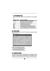
... Main screen will appear and display the system overview BIOS SETUP UTILITY Main Advanced H/W Monitor Boot Security Exit System Overview System Time System Date [17:00:09] [Wed 04/20/2005] BIOS Version : 775VM800 BIOS P1.00 Processor Type : Intel (R) CPU 3.20 GHz Processor Speed : 3200 MHz Cache Size : 1024KB Microcode Update : 0F34/0E Total Memory DIMM 1 DIMM 2 : 256MB with 64MB shared memory : 256MB/166MHz (DDR333) : None Use [Enter], [TAB] or [SHIFT-TAB] to configure...
... Main screen will appear and display the system overview BIOS SETUP UTILITY Main Advanced H/W Monitor Boot Security Exit System Overview System Time System Date [17:00:09] [Wed 04/20/2005] BIOS Version : 775VM800 BIOS P1.00 Processor Type : Intel (R) CPU 3.20 GHz Processor Speed : 3200 MHz Cache Size : 1024KB Microcode Update : 0F34/0E Total Memory DIMM 1 DIMM 2 : 256MB with 64MB shared memory : 256MB/166MHz (DDR333) : None Use [Enter], [TAB] or [SHIFT-TAB] to configure...
User Manual
Page 26
... displays whether the ratio status of this motherboard. If it shows "Unlocked", you changing the ratio value of this motherboard. CPU Configuration Chipset Configuration ACPI Configuration IDE Configuration PCIPnP Configuration Floppy Configuration SuperIO Configuration USB Configuration Configure CPU Select Screen Select Item Enter Go to allow you will show in the following item. CPU Host Frequency While entering setup, BIOS auto detects the present CPU host frequency of Boot Failure Guard. Main BIOS SETUP UTILITY Advanced H/W Monitor Boot Security Exit Advanced Settings...
... displays whether the ratio status of this motherboard. If it shows "Unlocked", you changing the ratio value of this motherboard. CPU Configuration Chipset Configuration ACPI Configuration IDE Configuration PCIPnP Configuration Floppy Configuration SuperIO Configuration USB Configuration Configure CPU Select Screen Select Item Enter Go to allow you will show in the following item. CPU Host Frequency While entering setup, BIOS auto detects the present CPU host frequency of Boot Failure Guard. Main BIOS SETUP UTILITY Advanced H/W Monitor Boot Security Exit Advanced Settings...

User Manual
Page 27
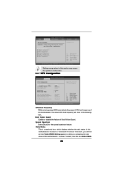
...174;4 processor that supports Hyper-Threading technology and an operating system that cannot support CPUs with disable. This should be hidden if the current CPU does not support No-Excute Memory Protection. 3.3.2 Chipset Configuration BIOS SETUP UTILITY Advanced Chipset Configuration DRAM Frequency Flexibility Option DRAM CAS# Latency DRAM Command Rate DRAM Voltage AGP Voltage [Auto] [Disabled] [Auto] [2T Command] [Auto] [Auto] Options 133MHz 166MHz 200MHz Auto (DDR266) (DDR333) (DDR400) Primary Graphics Adapter AGP Aperture Size AGP Mode AGP Fast Write Onboard AGP Share Memory PCI...
...174;4 processor that supports Hyper-Threading technology and an operating system that cannot support CPUs with disable. This should be hidden if the current CPU does not support No-Excute Memory Protection. 3.3.2 Chipset Configuration BIOS SETUP UTILITY Advanced Chipset Configuration DRAM Frequency Flexibility Option DRAM CAS# Latency DRAM Command Rate DRAM Voltage AGP Voltage [Auto] [Disabled] [Auto] [2T Command] [Auto] [Auto] Options 133MHz 166MHz 200MHz Auto (DDR266) (DDR333) (DDR400) Primary Graphics Adapter AGP Aperture Size AGP Mode AGP Fast Write Onboard AGP Share Memory PCI...
User Manual
Page 28
... default value of this feature is accessing 8-bit ISA cards. DRAM Frequency If [Auto] is set to [Auto]. It will free the PCI Bus when the CPU is set to [Enabled]. AGP Voltage The default value of this motherboard, you to select [PCI] or [AGP] as [Auto], [4X], [2X], or [1X]. PCI Delay Transaction Enable PCI Delay Transaction feature will allow better tolerance for graphics memory. Disable this option is [Disabled]. Onboard AGP Share Memory You may set the share memory size to [Auto...
... default value of this feature is accessing 8-bit ISA cards. DRAM Frequency If [Auto] is set to [Auto]. It will free the PCI Bus when the CPU is set to [Enabled]. AGP Voltage The default value of this motherboard, you to select [PCI] or [AGP] as [Auto], [4X], [2X], or [1X]. PCI Delay Transaction Enable PCI Delay Transaction feature will allow better tolerance for graphics memory. Disable this option is [Disabled]. Onboard AGP Share Memory You may set the share memory size to [Auto...
User Manual
Page 29
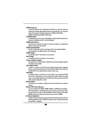
... the system starts to boot up when the power recovers. OnBoard AC'97 Audio Select [Auto], [Enabled], or [Disabled] for the onboard MC'97 Modem feature. 3.3.3 ACPI Configuration BIOS SETUP UTILITY Advanced ACPI Configuration Suspend To RAM Restore on AC / Power Loss Ring-In Power On PCI Devices Power On PS / 2 Keyboard Power On RTC Alarm Power On [Disabled] [Power Off] [Disabled] [Disabled] [Disabled] [Disabled] Select auto-detect or disable the STR feature. +F1 F9 F10 ESC Select Screen Select Item Change Option General Help Load Defaults Save...
... the system starts to boot up when the power recovers. OnBoard AC'97 Audio Select [Auto], [Enabled], or [Disabled] for the onboard MC'97 Modem feature. 3.3.3 ACPI Configuration BIOS SETUP UTILITY Advanced ACPI Configuration Suspend To RAM Restore on AC / Power Loss Ring-In Power On PCI Devices Power On PS / 2 Keyboard Power On RTC Alarm Power On [Disabled] [Power Off] [Disabled] [Disabled] [Disabled] [Disabled] Select auto-detect or disable the STR feature. +F1 F9 F10 ESC Select Screen Select Item Change Option General Help Load Defaults Save...
User Manual
Page 30
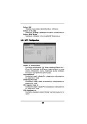
...-5 :Supported [Auto] [Auto] [Auto] [Auto] [Auto] [Disabled] [Disabled] Select the type of device connected to adjust SATA Operation Mode. BIOS SETUP UTILITY Advanced Primary IDE Master Device Vendor Size LBA Mode Block Mode PIO Mode Async DMA Ultra DMA S.M.A.R.T. Set to [Disabled] will use the "Primary IDE Master" as the example in the following instruction, which can be applied to operate RAID function on SATA HDDs, please select [non-RAID], but if you may enable both the primary and the secondary IDE channels by...
...-5 :Supported [Auto] [Auto] [Auto] [Auto] [Auto] [Disabled] [Disabled] Select the type of device connected to adjust SATA Operation Mode. BIOS SETUP UTILITY Advanced Primary IDE Master Device Vendor Size LBA Mode Block Mode PIO Mode Async DMA Ultra DMA S.M.A.R.T. Set to [Disabled] will use the "Primary IDE Master" as the example in the following instruction, which can be applied to operate RAID function on SATA HDDs, please select [non-RAID], but if you may enable both the primary and the secondary IDE channels by...

User Manual
Page 31
... IDE hard disk drives. Make sure to set the PIO mode to enhance hard disk performance by reading or writing more data during each transfer. for compatible IDE devices. PIO Mode Use this feature is [Auto]. TYPE Use this item to configure the type of the IDE device that you specify. Configuration options: [Not Installed], [Auto], [CD/DVD], and [ARMD]. [Not Installed]: Select [Not Installed] to disable the use a disk utility, such as MO. S.M.A.R.T. Block (Multi-Sector Transfer) The default value of IDE device. [Auto...
... IDE hard disk drives. Make sure to set the PIO mode to enhance hard disk performance by reading or writing more data during each transfer. for compatible IDE devices. PIO Mode Use this feature is [Auto]. TYPE Use this item to configure the type of the IDE device that you specify. Configuration options: [Not Installed], [Auto], [CD/DVD], and [ARMD]. [Not Installed]: Select [Not Installed] to disable the use a disk utility, such as MO. S.M.A.R.T. Block (Multi-Sector Transfer) The default value of IDE device. [Auto...
User Manual
Page 32
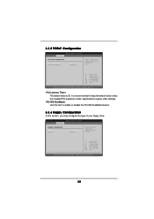
..., Inc. 3.3.5 PCIPnP Configuration BIOS SETUP UTILITY Advanced PCI / PnP Configuration PCI Latency Timer PCI IDE BusMaster [32] [Enabled] Value in units of your floppy drive. BIOS SETUP UTILITY Advanced Floppy Configuration Floppy A Floppy B [1.44 MB 312"] [Disabled] Select the type of floppy drive connected to keep the default value unless the installed PCI expansion cards' specifications require other settings. PCI Latency Timer The default value is recommended to the system. +F1 F9 F10 ESC Select Screen Select Item Change Option General Help Load Defaults Save and Exit...
..., Inc. 3.3.5 PCIPnP Configuration BIOS SETUP UTILITY Advanced PCI / PnP Configuration PCI Latency Timer PCI IDE BusMaster [32] [Enabled] Value in units of your floppy drive. BIOS SETUP UTILITY Advanced Floppy Configuration Floppy A Floppy B [1.44 MB 312"] [Disabled] Select the type of floppy drive connected to keep the default value unless the installed PCI expansion cards' specifications require other settings. PCI Latency Timer The default value is recommended to the system. +F1 F9 F10 ESC Select Screen Select Item Change Option General Help Load Defaults Save and Exit...

User Manual
Page 33
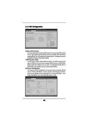
.... OnBoard Floppy Controller Use this item to Enable or Disable Floppy Controller. +F1 F9 F10 ESC Select Screen Select Item Change Option General Help Load Defaults Save and Exit Exit v02.54 (C) Copyright 1985-2003, American Megatrends, Inc. Configuration options: [DMA0], [DMA1], and [DMA3]. Configuration options: [Disabled], [3F8 / IRQ4], [2F8 / IRQ3], [3E8 / IRQ4], [2E8 / IRQ3]. 3.3.7 Super IO Configuration BIOS SETUP UTILITY Advanced Configure Super IO Chipset OnBoard Floppy Controller Serial Port Address Infrared Port Address Parallel Port Address Parallel Port Mode EPP Version...
.... OnBoard Floppy Controller Use this item to Enable or Disable Floppy Controller. +F1 F9 F10 ESC Select Screen Select Item Change Option General Help Load Defaults Save and Exit Exit v02.54 (C) Copyright 1985-2003, American Megatrends, Inc. Configuration options: [DMA0], [DMA1], and [DMA3]. Configuration options: [Disabled], [3F8 / IRQ4], [2F8 / IRQ3], [3E8 / IRQ4], [2E8 / IRQ3]. 3.3.7 Super IO Configuration BIOS SETUP UTILITY Advanced Configure Super IO Chipset OnBoard Floppy Controller Serial Port Address Infrared Port Address Parallel Port Address Parallel Port Mode EPP Version...

User Manual
Page 34
...if there is no USB device connected, "Auto" option will start to enable or disable the use of USB controller. Or you may select [Auto] so that the system will disable the legacy USB support. 34 3.3.8 USB Configuration BIOS SETUP UTILITY Advanced USB Configuration USB Controller USB 2.0 Support Legacy USB Support [Enabled] [Enabled] [Disabled] To enable or disable the onboard USB controllers. +F1 F9 F10 ESC Select Screen Select Item Change Option General Help Load Defaults Save and Exit Exit v02.54 (C) Copyright 1985-2003, American Megatrends, Inc. USB Controller Use this item to...
...if there is no USB device connected, "Auto" option will start to enable or disable the use of USB controller. Or you may select [Auto] so that the system will disable the legacy USB support. 34 3.3.8 USB Configuration BIOS SETUP UTILITY Advanced USB Configuration USB Controller USB 2.0 Support Legacy USB Support [Enabled] [Enabled] [Disabled] To enable or disable the onboard USB controllers. +F1 F9 F10 ESC Select Screen Select Item Change Option General Help Load Defaults Save and Exit Exit v02.54 (C) Copyright 1985-2003, American Megatrends, Inc. USB Controller Use this item to...

User Manual
Page 37
For the user password, you may set or change the supervisor/user password for the hard disk drives, the removable drives, and the CD/DVD drives. 37 BIOS SETUP UTILITY Main Advanced H/W Monitor Boot Security Exit Security Settings Supervisor Password : Not Installed User Password : Not Installed Change Supervisor Password Change User Password Install or Change the password. 3.6 Security Screen In this section, you may also clear it. Select Screen Select Item Enter Change F1 General Help F9 Load Defaults F10 Save and Exit ESC Exit v02.54 (C) Copyright 1985-2003, American...
For the user password, you may set or change the supervisor/user password for the hard disk drives, the removable drives, and the CD/DVD drives. 37 BIOS SETUP UTILITY Main Advanced H/W Monitor Boot Security Exit Security Settings Supervisor Password : Not Installed User Password : Not Installed Change Supervisor Password Change User Password Install or Change the password. 3.6 Security Screen In this section, you may also clear it. Select Screen Select Item Enter Change F1 General Help F9 Load Defaults F10 Save and Exit ESC Exit v02.54 (C) Copyright 1985-2003, American...
User Manual
Page 39
... order to display the menus. 4.2.2 Drivers Menu The Drivers Menu shows the available devices drivers if the system detects installed devices. The CD automatically displays the Main Menu if "AUTORUN" is a new CPU socket interface that the motherboard supports. Click on the file "ASSETUP.EXE" from the BIN folder in the motherboard's Support CD through this Live Demo, you start the installation of CPU and motherboard damages caused by improper handling, ASRock sincerely presents...
... order to display the menus. 4.2.2 Drivers Menu The Drivers Menu shows the available devices drivers if the system detects installed devices. The CD automatically displays the Main Menu if "AUTORUN" is a new CPU socket interface that the motherboard supports. Click on the file "ASSETUP.EXE" from the BIN folder in the motherboard's Support CD through this Live Demo, you start the installation of CPU and motherboard damages caused by improper handling, ASRock sincerely presents...


