User Manual
Page 8
... input, this motherboard supports 2-channel, 4-channel, 6-channel, and 8-channel modes. Please visit our website for details. 3. Microsoft® Windows® VistaTM / VistaTM 64-bit driver keeps on the motherboard functions properly and unplug the power cord, then plug it to spray thermal grease between the CPU and the heatsink when you resume the system, please check if the CPU fan on updating now. Although this motherboard offers stepless control, it...
... input, this motherboard supports 2-channel, 4-channel, 6-channel, and 8-channel modes. Please visit our website for details. 3. Microsoft® Windows® VistaTM / VistaTM 64-bit driver keeps on the motherboard functions properly and unplug the power cord, then plug it to spray thermal grease between the CPU and the heatsink when you resume the system, please check if the CPU fan on updating now. Although this motherboard offers stepless control, it...
User Manual
Page 10
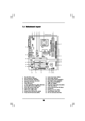
... Bridge Controller 3 ATX Power Connector (ATXPWR1) 16 Chassis Speaker Header (SPEAKER 1) 4 Chassis Fan Connector (CHA_FAN1) 17 Clear CMOS Jumper (CLRCMOS1) 5 North Bridge Controller 18 Floppy Connector (FLOPPY1) 6 775-Pin CPU Socket 19 HDMR Slot (HDMR1) 7 2 x 184-pin DDR DIMM Slots (DDR1, DDR2; Blue) 20 Front Panel Audio Header (HD_AUDIO1) 8 Secondary IDE Connector (IDE2, Black) 21 3 x PCI Slots (PCI1- 3) 9 Primary IDE Connector (IDE1, Blue) 22 Internal Audio Connector: CD1 (Black) 10 USB 2.0 Header (USB4_5, Blue) 23 Flash Memory 11 USB 2.0 Header (USB6_7, Blue) 24 PCI Express...
... Bridge Controller 3 ATX Power Connector (ATXPWR1) 16 Chassis Speaker Header (SPEAKER 1) 4 Chassis Fan Connector (CHA_FAN1) 17 Clear CMOS Jumper (CLRCMOS1) 5 North Bridge Controller 18 Floppy Connector (FLOPPY1) 6 775-Pin CPU Socket 19 HDMR Slot (HDMR1) 7 2 x 184-pin DDR DIMM Slots (DDR1, DDR2; Blue) 20 Front Panel Audio Header (HD_AUDIO1) 8 Secondary IDE Connector (IDE2, Black) 21 3 x PCI Slots (PCI1- 3) 9 Primary IDE Connector (IDE1, Blue) 22 Internal Audio Connector: CD1 (Black) 10 USB 2.0 Header (USB4_5, Blue) 23 Flash Memory 11 USB 2.0 Header (USB6_7, Blue) 24 PCI Express...
User Manual
Page 20
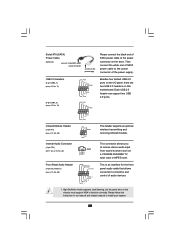
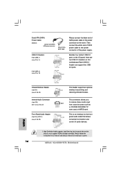
... instruction in our manual and chassis manual to the power connector of the power supply. USB 2.0 Headers (9-pin USB6_7) (see p.10 No. 11) (9-pin USB4_5) (see p.10 No. 10) USB_PWR P-7 P+7 GND DUMMY 1 GND P+6 P-6 USB_PWR USB_PWR P-4 P+4 GND DUMMY 1 GND P+5 P-5 USB_PWR Besides four default USB 2.0 ports on the I/O panel, there are two USB 2.0 headers on the drive. Serial ATA (SATA) Power Cable (Optional) connect to the SATA HDD power connector connect to the power supply Please connect the black end of SATA power cable to the power connector on this motherboard...
... instruction in our manual and chassis manual to the power connector of the power supply. USB 2.0 Headers (9-pin USB6_7) (see p.10 No. 11) (9-pin USB4_5) (see p.10 No. 10) USB_PWR P-7 P+7 GND DUMMY 1 GND P+6 P-6 USB_PWR USB_PWR P-4 P+4 GND DUMMY 1 GND P+5 P-5 USB_PWR Besides four default USB 2.0 ports on the I/O panel, there are two USB 2.0 headers on the drive. Serial ATA (SATA) Power Cable (Optional) connect to the SATA HDD power connector connect to the power supply Please connect the black end of SATA power cable to the power connector on this motherboard...

User Manual
Page 24
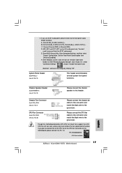
...below cable accessories from the motherboard gift box pack. SATA power cable SATA 7-pin connector The SATA 15-pin power connector (Black) connect to SATA HDD 1x4-pin conventional power connector (White) connect to power supply Caution 1. Make sure to use the SATA power cable & data cable, which are from your dealer or HDD user manual. Please follow below operation guide of SATA HDD Hot Plug feature carefully. 2.11 SATA HDD Hot Plug Feature and Operation Guide This motherboard supports Hot Plug feature for our motherboard, which supports SATA HDD Hot Plug. * The SATA Hot Plug feature...
...below cable accessories from the motherboard gift box pack. SATA power cable SATA 7-pin connector The SATA 15-pin power connector (Black) connect to SATA HDD 1x4-pin conventional power connector (White) connect to power supply Caution 1. Make sure to use the SATA power cable & data cable, which are from your dealer or HDD user manual. Please follow below operation guide of SATA HDD Hot Plug feature carefully. 2.11 SATA HDD Hot Plug Feature and Operation Guide This motherboard supports Hot Plug feature for our motherboard, which supports SATA HDD Hot Plug. * The SATA Hot Plug feature...
User Manual
Page 28
... boot your SATA HDDs with RAID functions, please follow the instruction to install Windows® VistaTM / Windows® VistaTM 64-bit OS on the bottom to install Windows?" page, please insert the ASRock Support CD into the optical drive again to manage (create, convert, delete, or rebuild) RAID functions on SATA HDDs,please set the RAID configuration by using the Windows RAID installation guide part of the document in the following path in the Support CD: .. \ RAID Installation Guide 2. STEP 2: Use "RAID Installation Guide...
... boot your SATA HDDs with RAID functions, please follow the instruction to install Windows® VistaTM / Windows® VistaTM 64-bit OS on the bottom to install Windows?" page, please insert the ASRock Support CD into the optical drive again to manage (create, convert, delete, or rebuild) RAID functions on SATA HDDs,please set the RAID configuration by using the Windows RAID installation guide part of the document in the following path in the Support CD: .. \ RAID Installation Guide 2. STEP 2: Use "RAID Installation Guide...
User Manual
Page 32
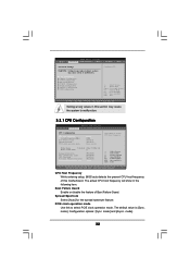
... the spread spectrum feature. The actual CPU host frequency will show in this motherboard. Configuration options: [Sync. Setting wrong values in the following item. mode]. 32 Boot Failure Guard Enable or disable the feature of this section may cause system to select PCIE clock operation mode. CPU Configuration Chipset Configuration ACPI Configuration IDE Configuration PCIPnP Configuration Floppy Configuration SuperIO Configuration USB Configuration Configure CPU Select Screen Select Item Enter Go to Sub Screen F1 General Help F9 Load Defaults F10 Save and Exit ESC Exit...
... the spread spectrum feature. The actual CPU host frequency will show in this motherboard. Configuration options: [Sync. Setting wrong values in the following item. mode]. 32 Boot Failure Guard Enable or disable the feature of this section may cause system to select PCIE clock operation mode. CPU Configuration Chipset Configuration ACPI Configuration IDE Configuration PCIPnP Configuration Floppy Configuration SuperIO Configuration USB Configuration Configure CPU Select Screen Select Item Enter Go to Sub Screen F1 General Help F9 Load Defaults F10 Save and Exit ESC Exit...
User Manual
Page 33
... cannot support CPUs with disable. Max CPUID Value Limit For Prescott CPU only, some OSes (ex. Intel (R) Virtualization tech. CPU Thermal Throttling You may select [Enabled] to enable P4 CPU internal thermal control mechanism to boot legacy OSes that includes optimization for this technology, such as Microsoft® 33 Ratio Status This is a read -only item, which displays whether the ratio status of this motherboard. Ratio...
... cannot support CPUs with disable. Max CPUID Value Limit For Prescott CPU only, some OSes (ex. Intel (R) Virtualization tech. CPU Thermal Throttling You may select [Enabled] to enable P4 CPU internal thermal control mechanism to boot legacy OSes that includes optimization for this technology, such as Microsoft® 33 Ratio Status This is a read -only item, which displays whether the ratio status of this motherboard. Ratio...
User Manual
Page 37
...to set the drive strength of VIA chipset. configuration options: [Normal], [Fast]. OnBoard HD Audio Select [Auto], [Enabled] or [Disabled] for the onboard HD Audio Front Panel. If you to enable or disable the onboard LAN feature. The default value is plugged. OnBoard LAN This allows you select [Auto], the onboard HD Audio will be disabled when PCI Sound Card is [Normal]. Echo TRP Disable The default value of OnBoard HD Audio. Front Panel Control Select [Auto], [Enabled] or [Disabled] for the onboard HD Audio feature. Configuration options: [Low], [Normal], [High] and...
...to set the drive strength of VIA chipset. configuration options: [Normal], [Fast]. OnBoard HD Audio Select [Auto], [Enabled] or [Disabled] for the onboard HD Audio Front Panel. If you to enable or disable the onboard LAN feature. The default value is plugged. OnBoard LAN This allows you select [Auto], the onboard HD Audio will be disabled when PCI Sound Card is [Normal]. Echo TRP Disable The default value of OnBoard HD Audio. Front Panel Control Select [Auto], [Enabled] or [Disabled] for the onboard HD Audio feature. Configuration options: [Low], [Normal], [High] and...
User Manual
Page 39
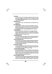
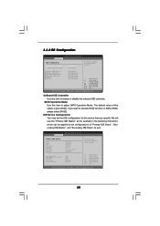
... SATA 1 SATA 2 [Hard Disk] [Not Detected] [Not Detected] [Not Detected] [Not Detected] [Not Detected] +F1 F9 F10 ESC Select Screen Select Item Change Option General Help Load Defaults Save and Exit Exit v02.54 (C) Copyright 1985-2003, American Megatrends, Inc. OnBoard IDE Controller Use this item to operate RAID function on SATA HDDs, please select [RAID]. IDE Device Configuration You may set the IDE configuration for the device that you want to adjust SATA Operation Mode. BIOS SETUP UTILITY...
... SATA 1 SATA 2 [Hard Disk] [Not Detected] [Not Detected] [Not Detected] [Not Detected] [Not Detected] +F1 F9 F10 ESC Select Screen Select Item Change Option General Help Load Defaults Save and Exit Exit v02.54 (C) Copyright 1985-2003, American Megatrends, Inc. OnBoard IDE Controller Use this item to operate RAID function on SATA HDDs, please select [RAID]. IDE Device Configuration You may set the IDE configuration for the device that you want to adjust SATA Operation Mode. BIOS SETUP UTILITY...

User Manual
Page 40
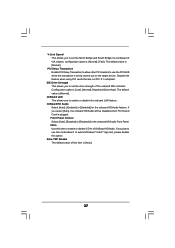
... and UNIX user, select [Disabled] to automatically detect the hard disk drive. Configuration options: [Disabled], [Auto], [Enabled]. 32-Bit Data Transfer Use this item to disable the use a disk utility, such as MO. LBA/Large Mode Use this item is used for compatible IDE devices. This is enabled, it will enhance hard disk performance by optimizing the hard disk timing. Configuration options: [Not Installed], [Auto], [CD/DVD], and [ARMD]. [Not Installed]: Select [Not Installed] to enable or disable the S.M.A.R.T. (Self-Monitoring, Analysis, and Reporting Technology) feature.
... and UNIX user, select [Disabled] to automatically detect the hard disk drive. Configuration options: [Disabled], [Auto], [Enabled]. 32-Bit Data Transfer Use this item to disable the use a disk utility, such as MO. LBA/Large Mode Use this item is used for compatible IDE devices. This is enabled, it will enhance hard disk performance by optimizing the hard disk timing. Configuration options: [Not Installed], [Auto], [CD/DVD], and [ARMD]. [Not Installed]: Select [Not Installed] to enable or disable the S.M.A.R.T. (Self-Monitoring, Analysis, and Reporting Technology) feature.
User Manual
Page 46
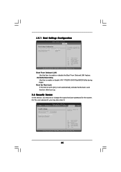
.../user password for the system. Select Screen Select Item Enter Change F1 General Help F9 Load Defaults F10 Save and Exit ESC Exit v02.54 (C) Copyright 1985-2003, American Megatrends, Inc. 46 BIOS SETUP UTILITY Main Advanced H/W Monitor Boot Security Exit Security Settings Supervisor Password : Not Installed User Password : Not Installed Change Supervisor Password Change User Password Clear User Password Install or Change the password. Boot Up Num-Lock If this section, you may set to enable or disable the Boot From Onboard LAN feature. VIA SATA Raid Utility Use...
.../user password for the system. Select Screen Select Item Enter Change F1 General Help F9 Load Defaults F10 Save and Exit ESC Exit v02.54 (C) Copyright 1985-2003, American Megatrends, Inc. 46 BIOS SETUP UTILITY Main Advanced H/W Monitor Boot Security Exit Security Settings Supervisor Password : Not Installed User Password : Not Installed Change Supervisor Password Change User Password Clear User Password Install or Change the password. Boot Up Num-Lock If this section, you may set to enable or disable the Boot From Onboard LAN feature. VIA SATA Raid Utility Use...

User Manual
Page 48
... This motherboard supports various Microsoft® Windows® operating systems: 2000 / XP / XP 64-bit / VistaTM / VistaTM 64-bit. Please install the necessary drivers to install it. 4.2.4 Contact Information If you may contact your CD-ROM drive. Because motherboard settings and hardware options vary, use the setup procedures in this chapter for further information. 48 If the Main Menu did not appear automatically, locate and double click on a specific...
... This motherboard supports various Microsoft® Windows® operating systems: 2000 / XP / XP 64-bit / VistaTM / VistaTM 64-bit. Please install the necessary drivers to install it. 4.2.4 Contact Information If you may contact your CD-ROM drive. Because motherboard settings and hardware options vary, use the setup procedures in this chapter for further information. 48 If the Main Menu did not appear automatically, locate and double click on a specific...
Quick Installation Guide
Page 4
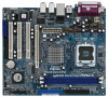
... VGA cards and CPU support lists on ASRock website without notice. Because the motherboard specifications and the BIOS software might be updated, the content of the motherboard can be found in the user manual presented in Floppy Drive One Serial ATA (SATA) Cable (Optional) One Serial ATA (SATA) HDD Power Cable (Optional) One ASRock 8CH I/O Plus Panel Shield 4 ASRock 4CoreDX90-VSTA Motherboard English In case any modifications of the motherboard and step-bystep installation guide. ASRock website http://www.asrock.com 1.1 Package Contents ASRock 4CoreDX90-VSTA Motherboard (Micro ATX...
... VGA cards and CPU support lists on ASRock website without notice. Because the motherboard specifications and the BIOS software might be updated, the content of the motherboard can be found in the user manual presented in Floppy Drive One Serial ATA (SATA) Cable (Optional) One Serial ATA (SATA) HDD Power Cable (Optional) One ASRock 8CH I/O Plus Panel Shield 4 ASRock 4CoreDX90-VSTA Motherboard English In case any modifications of the motherboard and step-bystep installation guide. ASRock website http://www.asrock.com 1.1 Package Contents ASRock 4CoreDX90-VSTA Motherboard (Micro ATX...
Quick Installation Guide
Page 6
... connectors (support 4 x IDE devices) - 1 x Floppy connector - 1 x IR header - SMBIOS 2.3.1 Support - Chassis Fan Tachometer - Chassis Temperature Sensing - Microsoft® Windows® 2000 / XP / XP 64-bit / VistaTM / VistaTM 64-bit compliant (see CAUTION 6) - 4Mb AMI BIOS - Supports jumperfree - Voltage Monitoring: +12V, +5V, +3.3V, Vcore - It should be done at your system. ACPI 1.1 Compliance Wake Up Events - Front panel audio connector - 2 x USB 2.0 headers (support 4 USB 2.0 ports) (see CAUTION 7) - CPU/Chassis FAN connector - 20 pin ATX power connector - 4 pin...
... connectors (support 4 x IDE devices) - 1 x Floppy connector - 1 x IR header - SMBIOS 2.3.1 Support - Chassis Fan Tachometer - Chassis Temperature Sensing - Microsoft® Windows® 2000 / XP / XP 64-bit / VistaTM / VistaTM 64-bit compliant (see CAUTION 6) - 4Mb AMI BIOS - Supports jumperfree - Voltage Monitoring: +12V, +5V, +3.3V, Vcore - It should be done at your system. ACPI 1.1 Compliance Wake Up Events - Front panel audio connector - 2 x USB 2.0 headers (support 4 USB 2.0 ports) (see CAUTION 7) - CPU/Chassis FAN connector - 20 pin ATX power connector - 4 pin...
Quick Installation Guide
Page 7
... CPU fan on updating now. For audio output, this motherboard supports both stereo and mono modes. Power Management for Microsoft® Windows® VistaTM / VistaTM 64-bit driver and related information. Please visit our website for USB 2.0 works fine under Microsoft® Windows® VistaTM 64-bit / VistaTM / XP 64-bit / XP SP1 or SP2 / 2000 SP4. 7. Before you install the PC system. 5. ASRock website http://www.asrock.com 7 ASRock 4CoreDX90-VSTA Motherboard...
... CPU fan on updating now. For audio output, this motherboard supports both stereo and mono modes. Power Management for Microsoft® Windows® VistaTM / VistaTM 64-bit driver and related information. Please visit our website for USB 2.0 works fine under Microsoft® Windows® VistaTM 64-bit / VistaTM / XP 64-bit / XP SP1 or SP2 / 2000 SP4. 7. Before you install the PC system. 5. ASRock website http://www.asrock.com 7 ASRock 4CoreDX90-VSTA Motherboard...
Quick Installation Guide
Page 16
... ASRock 4CoreDX90-VSTA Motherboard English Please follow the instruction in our manual and chassis manual to receive stereo audio input CD1 from sound sources such as a CD-ROM, DVD-ROM, TV tuner card, or MPEG card. Each USB 2.0 header can support two USB 2.0 ports. Infrared Module Header (5-pin IR1) (see p.2, No. 25) Internal Audio Connector (4-pin CD1) (CD1: see p.2, No. 22) Front Panel Audio Header (9-pin HD_AUDIO1) (see p.2 No. 10) Besides four default USB 2.0 ports on the I/O panel, there are two USB 2.0 headers on this motherboard. Serial ATA (SATA) Power Cable (Optional...
... ASRock 4CoreDX90-VSTA Motherboard English Please follow the instruction in our manual and chassis manual to receive stereo audio input CD1 from sound sources such as a CD-ROM, DVD-ROM, TV tuner card, or MPEG card. Each USB 2.0 header can support two USB 2.0 ports. Infrared Module Header (5-pin IR1) (see p.2, No. 25) Internal Audio Connector (4-pin CD1) (CD1: see p.2, No. 22) Front Panel Audio Header (9-pin HD_AUDIO1) (see p.2 No. 10) Besides four default USB 2.0 ports on the I/O panel, there are two USB 2.0 headers on this motherboard. Serial ATA (SATA) Power Cable (Optional...
Quick Installation Guide
Page 17
... this header. Enter Windows system. Pin 1-3 Connected 3-Pin Fan Installation 17 ASRock 4CoreDX90-VSTA Motherboard English If you plan to connect the 3-Pin CPU fan to the CPU fan connector on the lower right hand taskbar to enter Realtek HD Audio Manager. Connect Mic_IN (MIC) to [Enabled]. Click "Audio I/O", select "Connector Settings" , choose "Disable front panel jack detection", and save the change by clicking "OK". Connect Audio_R (RIN) to OUT2_R and Audio_L (LIN) to Ground (GND). Connect Ground (GND) to OUT2_L. Chassis Speaker Header (4-pin SPEAKER...
... this header. Enter Windows system. Pin 1-3 Connected 3-Pin Fan Installation 17 ASRock 4CoreDX90-VSTA Motherboard English If you plan to connect the 3-Pin CPU fan to the CPU fan connector on the lower right hand taskbar to enter Realtek HD Audio Manager. Connect Mic_IN (MIC) to [Enabled]. Click "Audio I/O", select "Connector Settings" , choose "Disable front panel jack detection", and save the change by clicking "OK". Connect Audio_R (RIN) to OUT2_R and Audio_L (LIN) to Ground (GND). Connect Ground (GND) to OUT2_L. Chassis Speaker Header (4-pin SPEAKER...
Quick Installation Guide
Page 19
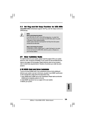
... drivers compatible to HDMR slot on this motherboard. Insert HDMR card to your system, please insert the support CD to use HDMR card function on the support CD driver page. 2.8 Hot Plug and Hot Swap Functions for SATA HDDs 4CoreDX90-VSTA motherboard supports Hot Plug and Hot Swap functions for the action to insert and remove the SATA HDDs while the system is still power-on and in working condition. 2.9 Driver Installation Guide To install the drivers to...
... drivers compatible to HDMR slot on this motherboard. Insert HDMR card to your system, please insert the support CD to use HDMR card function on the support CD driver page. 2.8 Hot Plug and Hot Swap Functions for SATA HDDs 4CoreDX90-VSTA motherboard supports Hot Plug and Hot Swap functions for the action to insert and remove the SATA HDDs while the system is still power-on and in working condition. 2.9 Driver Installation Guide To install the drivers to...
Quick Installation Guide
Page 21
... IDE HDDs and want to load the VIA® RAID drivers. VIA® RAID drivers are in the following path in the Support CD: .. \ RAID Installation Guide 2. If you want to install Windows® VistaTM or Windows® VistaTM 64-bit on the bottom to install Windows?" A. Enter BIOS SETUP UTILITY Advanced screen IDE Configuration. B. Before you start to configure RAID function, you want to manage (create, convert, delete, or rebuild) RAID functions on SATA HDDs, please set the RAID configuration by using the Windows RAID installation guide part...
... IDE HDDs and want to load the VIA® RAID drivers. VIA® RAID drivers are in the following path in the Support CD: .. \ RAID Installation Guide 2. If you want to install Windows® VistaTM or Windows® VistaTM 64-bit on the bottom to install Windows?" A. Enter BIOS SETUP UTILITY Advanced screen IDE Configuration. B. Before you start to configure RAID function, you want to manage (create, convert, delete, or rebuild) RAID functions on SATA HDDs, please set the RAID configuration by using the Windows RAID installation guide part...

Quick Installation Guide
Page 23
... Flash Memory on the file "ASSETUP. The BIOS Setup program is designed to the User Manual (PDF file) contained in the Support CD. 4. The Support CD that will display the Main Menu automatically if "AUTORUN" is a menu-driven program, which allows you start up the computer, please press during the Power-On-Self-Test (POST) to select among the predetermined choices. otherwise, POST continues with the motherboard contains necessary drivers and useful utilities...
... Flash Memory on the file "ASSETUP. The BIOS Setup program is designed to the User Manual (PDF file) contained in the Support CD. 4. The Support CD that will display the Main Menu automatically if "AUTORUN" is a menu-driven program, which allows you start up the computer, please press during the Power-On-Self-Test (POST) to select among the predetermined choices. otherwise, POST continues with the motherboard contains necessary drivers and useful utilities...


