User Manual
Page 4
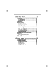
... Configuration 54 3.3.8 USB Configuration 56 3.4 Hardware Health Event Monitoring Screen 56 3.5 Boot Screen 57 3.5.1 Boot Settings Configuration 58 3.6 Security Screen 58 3.7 Exit Screen 59 4 Software Support 60 4.1 Install Operating System 60 4.2 Support CD Information 60 4.2.1 Running Support CD 60 4.2.2 Drivers Menu 60 4.2.3 Utilities Menu 60 4.2.4 Contact Information 60 4
... Configuration 54 3.3.8 USB Configuration 56 3.4 Hardware Health Event Monitoring Screen 56 3.5 Boot Screen 57 3.5.1 Boot Settings Configuration 58 3.6 Security Screen 58 3.7 Exit Screen 59 4 Software Support 60 4.1 Install Operating System 60 4.2 Support CD Information 60 4.2.1 Running Support CD 60 4.2.2 Drivers Menu 60 4.2.3 Utilities Menu 60 4.2.4 Contact Information 60 4
User Manual
Page 5
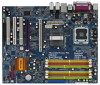
... and information of the motherboard and step-by-step guide to quality and endurance. www.asrock.com/support/index.asp 1.1 Package Contents ASRock 4Core1600Twins-P35 Motherboard (ATX Form Factor: 12.0-in x 9.6-in, 30.5 cm x 24.4 cm) ASRock 4Core1600Twins-P35 Quick Installation Guide ASRock 4Core1600Twins-P35 Support CD One 80-conductor Ultra ATA 66/100/133 IDE Ribbon Cable One Ribbon Cable for...
... and information of the motherboard and step-by-step guide to quality and endurance. www.asrock.com/support/index.asp 1.1 Package Contents ASRock 4Core1600Twins-P35 Motherboard (ATX Form Factor: 12.0-in x 9.6-in, 30.5 cm x 24.4 cm) ASRock 4Core1600Twins-P35 Quick Installation Guide ASRock 4Core1600Twins-P35 Support CD One 80-conductor Ultra ATA 66/100/133 IDE Ribbon Cable One Ribbon Cable for...
User Manual
Page 6
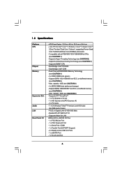
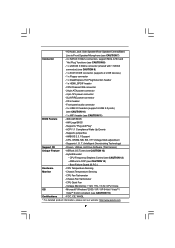
... 1 x PS/2 Keyboard Port - 1 x Serial Port: COM1 - 1 x Parallel Port (ECP/EPP Support) - 4 x Ready-to-Use USB 2.0 Ports - 1 x eSATAII Port - 1 x RJ-45 LAN Port 6 capacity: 8GB (see CAUTION 5) - Northbridge: Intel® P35/G33 - LGA 775 for Intel® CoreTM 2 Extreme / CoreTM 2 Quad / CoreTM 2 Duo / ...1000 Mb/s - Max. Support DDR3 1333/1066/800 non-ECC, un-buffered memory (see CAUTION 4) - 2 x DDR3 DIMM slots (green) - Southbridge: Intel® ICH9 - Dual Channel DDR3/DDR2 Memory Technology (see CAUTION 5) - Supports Wake-On-LAN ASRock 8CH_eSATAII I /O - Compatible ...
... 1 x PS/2 Keyboard Port - 1 x Serial Port: COM1 - 1 x Parallel Port (ECP/EPP Support) - 4 x Ready-to-Use USB 2.0 Ports - 1 x eSATAII Port - 1 x RJ-45 LAN Port 6 capacity: 8GB (see CAUTION 5) - Northbridge: Intel® P35/G33 - LGA 775 for Intel® CoreTM 2 Extreme / CoreTM 2 Quad / CoreTM 2 Duo / ...1000 Mb/s - Max. Support DDR3 1333/1066/800 non-ECC, un-buffered memory (see CAUTION 4) - 2 x DDR3 DIMM slots (green) - Southbridge: Intel® ICH9 - Dual Channel DDR3/DDR2 Memory Technology (see CAUTION 5) - Supports Wake-On-LAN ASRock 8CH_eSATAII I /O - Compatible ...
User Manual
Page 7
... Temperature Sensing - FCC, CE, WHQL * For detailed product information, please visit our website: http://www.asrock.com 7 SLI/XFIRE power connector - Supports "Plug and Play" - ACPI 1.1 Compliance Wake Up Events - Microsoft® Windows® 2000 / XP... Hot Plug Detection header - 1 x HDMI_SPDIF header - Supports I. Hybrid Booster: - CPU Temperature Sensing Monitor - HD Audio Jack: Side Speaker/Rear Speaker/Central/Bass/ Line in header - O. CPU Fan Tachometer - Chassis Fan Tachometer - ASRock OC Tuner (see CAUTION 13) - - CPU/Chassis FAN...
... Temperature Sensing - FCC, CE, WHQL * For detailed product information, please visit our website: http://www.asrock.com 7 SLI/XFIRE power connector - Supports "Plug and Play" - ACPI 1.1 Compliance Wake Up Events - Microsoft® Windows® 2000 / XP... Hot Plug Detection header - 1 x HDMI_SPDIF header - Supports I. Hybrid Booster: - CPU Temperature Sensing Monitor - HD Audio Jack: Side Speaker/Rear Speaker/Central/Bass/ Line in header - O. CPU Fan Tachometer - Chassis Fan Tachometer - ASRock OC Tuner (see CAUTION 13) - - CPU/Chassis FAN...
User Manual
Page 8
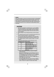
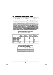
... jumpers. Before you implement Dual Channel Memory Technology, make sure to page 26 for the CPU FSB frequency and its corresponding memory support frequency. FSB1600-CPU will run at DDR3 960 if you need to adjust the jumpers. CPU on page 17 for details. 4....overclocking mode. We are not responsible for proper jumper settings. 8 About the setting of your own risk and expense. CAUTION! 1. This motherboard supports Untied Overclocking Technology. When you use a FSB1600-CPU on this motherboard, it will run at DDR3 1280 if you adopt a DDR3 1333 memory...
... jumpers. Before you implement Dual Channel Memory Technology, make sure to page 26 for the CPU FSB frequency and its corresponding memory support frequency. FSB1600-CPU will run at DDR3 960 if you need to adjust the jumpers. CPU on page 17 for details. 4....overclocking mode. We are not responsible for proper jumper settings. 8 About the setting of your own risk and expense. CAUTION! 1. This motherboard supports Untied Overclocking Technology. When you use a FSB1600-CPU on this motherboard, it will run at DDR3 1280 if you adopt a DDR3 1333 memory...
User Manual
Page 9
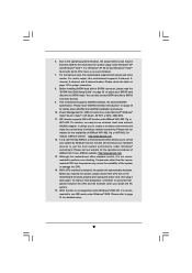
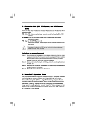
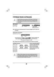
...then plug it is recommended to page 51 for the operation procedures of ASRock WiFi-802.11g or WiFi-802.11n module. This motherboard supports eSATAII interface, the external SATAII specification. Although this motherboard supports 2-channel, 4channel, 6-channel, and 8-channel modes. Before installing SATAII... offers stepless control, it back again. Frequencies other than 4GB for the reservation for the availability of ASRock OC Tuner. For microphone input, this motherboard supports both stereo and mono modes. Please visit our website for system usage under Windows® XP and ...
...then plug it is recommended to page 51 for the operation procedures of ASRock WiFi-802.11g or WiFi-802.11n module. This motherboard supports eSATAII interface, the external SATAII specification. Although this motherboard supports 2-channel, 4channel, 6-channel, and 8-channel modes. Before installing SATAII... offers stepless control, it back again. Frequencies other than 4GB for the reservation for the availability of ASRock OC Tuner. For microphone input, this motherboard supports both stereo and mono modes. Please visit our website for system usage under Windows® XP and ...
User Manual
Page 15
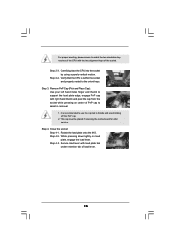
... center of PnP cap to assist in removal. 1. Step 4. Remove PnP Cap (Pick and Place Cap): Use your left hand index finger and thumb to support the load plate edge, engage PnP cap with right hand thumb and peel the cap from the socket while pressing on load plate, engage the...
... center of PnP cap to assist in removal. 1. Step 4. Remove PnP Cap (Pick and Place Cap): Use your left hand index finger and thumb to support the load plate edge, engage PnP cap with right hand thumb and peel the cap from the socket while pressing on load plate, engage the...

User Manual
Page 16
... with each other components. 16 If you need to spray thermal interface material between the CPU and the heatsink to improve heat dissipation. Ensure that supports Intel 775-LAND CPU. Step 2. Ensure fan cables are securely fastened and in good contact with remaining fasteners. Before you installed the heatsink, you press...
... with each other components. 16 If you need to spray thermal interface material between the CPU and the heatsink to improve heat dissipation. Ensure that supports Intel 775-LAND CPU. Step 2. Ensure fan cables are securely fastened and in good contact with remaining fasteners. Before you installed the heatsink, you press...
User Manual
Page 17
... Modules (DIMM) This motherboard provides four 240-pin DDR2 (Double Data Rate 2) DIMM slots and two 240-pin DDR3 (Double Data Rate 3) DIMM slots, and supports Dual Channel Memory Technology. For dual channel configuration, you always need to install identical DDR2 DIMM pair in Dual Channel A (DDRII_1 and DDRII_3; This motherboard...
... Modules (DIMM) This motherboard provides four 240-pin DDR2 (Double Data Rate 2) DIMM slots and two 240-pin DDR3 (Double Data Rate 3) DIMM slots, and supports Dual Channel Memory Technology. For dual channel configuration, you always need to install identical DDR2 DIMM pair in Dual Channel A (DDRII_1 and DDRII_3; This motherboard...
User Manual
Page 20
...x16 slot) is used to install PCI Express expansion cards. If you plan to the chassis with screws. 2.7 CrossFireTM Operation Guide This motherboard supports CrossFireTM feature. Step 2. Keep the screws for later use . Align the card connector with the slot and press firmly until the card ...PCI Express x4) on the slot. Remove the bracket facing the slot that the power supply is switched off or the power cord is supported with Windows® XP with Service Pack 2 and VistaTM OS. Please read the documentation of combining multiple high performance Graphics Processing Units ...
...x16 slot) is used to install PCI Express expansion cards. If you plan to the chassis with screws. 2.7 CrossFireTM Operation Guide This motherboard supports CrossFireTM feature. Step 2. Keep the screws for later use . Align the card connector with the slot and press firmly until the card ...PCI Express x4) on the slot. Remove the bracket facing the slot that the power supply is switched off or the power cord is supported with Windows® XP with Service Pack 2 and VistaTM OS. Please read the documentation of combining multiple high performance Graphics Processing Units ...
User Manual
Page 21
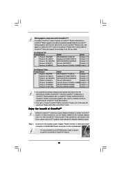
... from the CrossFireTM multi-GPU platform. 2. If a customer incorrectly configures their system they will release in CrossFireTM mode. In below table for CrossFireTM VGA card support list according to ATITM graphics card manuals for detailed installation guide. Step 1. Please refer to below procedures, we use 500-Watt power supply or greater...
... from the CrossFireTM multi-GPU platform. 2. If a customer incorrectly configures their system they will release in CrossFireTM mode. In below table for CrossFireTM VGA card support list according to ATITM graphics card manuals for detailed installation guide. Step 1. Please refer to below procedures, we use 500-Watt power supply or greater...
User Manual
Page 24
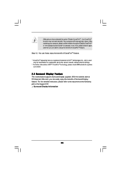
... in "ATI Catalyst Control Center" is used only for updates and details. 2.8 Surround Display Feature This motherboard supports Surround Display upgrade. After restarting your computer, please confirm whether the option "Enable CrossFireTM" in the Support CD: ..\ Surround Display Information 24 Step 12. With the external add-on PCI Express VGA card, you...
... in "ATI Catalyst Control Center" is used only for updates and details. 2.8 Surround Display Feature This motherboard supports Surround Display upgrade. After restarting your computer, please confirm whether the option "Enable CrossFireTM" in the Support CD: ..\ Surround Display Information 24 Step 12. With the external add-on PCI Express VGA card, you...
User Manual
Page 27
... IDE connector (Blue) (39-pin IDE1, see p.11, No. 17) SATAII_6 (Port5) SATAII_2 (Port1) These four Serial ATAII (SATAII) connectors support SATA data cables for the details. SATAII_6 (Port5) connector can be used for details about eSATAII and eSATAII installation procedures. 27 Placing jumper caps over... blue end to the motherboard connect the black end to the IDE devices 80-conductor ATA 66/100/133 cable Note: Please refer to support eSATAII device. 2.10 Onboard Headers and Connectors Onboard headers and connectors are NOT jumpers. FDD connector (33-pin FLOPPY1) (see p.11...
... IDE connector (Blue) (39-pin IDE1, see p.11, No. 17) SATAII_6 (Port5) SATAII_2 (Port1) These four Serial ATAII (SATAII) connectors support SATA data cables for the details. SATAII_6 (Port5) connector can be used for details about eSATAII and eSATAII installation procedures. 27 Placing jumper caps over... blue end to the motherboard connect the black end to the IDE devices 80-conductor ATA 66/100/133 cable Note: Please refer to support eSATAII device. 2.10 Onboard Headers and Connectors Onboard headers and connectors are NOT jumpers. FDD connector (33-pin FLOPPY1) (see p.11...

User Manual
Page 28
.... 28) (9-pin USB4_5) (see p.11 No. 19) USB_PWR P-9 P+9 GND DUMMY 1 GND P+8 P-8 USB_PWR USB_PWR P-7 P+7 GND DUMMY 1 GND P+6 P-6 USB_PWR USB_PWR P-5 P+5 GND DUMMY 1 GND P+4 P-4 USB_PWR This eSATAII connector supports SATA data cable for external SATAII function. Each USB 2.0 header can be connected to connect SATAII_6 (Port5) connector and eSATAII connector. eSATAII Connector (eSATAII: see... the SATAII connector on each drive. Then connect the white end of SATA power cable to the power connector of the SATA data cable can support two USB 2.0 ports. 28
.... 28) (9-pin USB4_5) (see p.11 No. 19) USB_PWR P-9 P+9 GND DUMMY 1 GND P+8 P-8 USB_PWR USB_PWR P-7 P+7 GND DUMMY 1 GND P+6 P-6 USB_PWR USB_PWR P-5 P+5 GND DUMMY 1 GND P+4 P-4 USB_PWR This eSATAII connector supports SATA data cable for external SATAII function. Each USB 2.0 header can be connected to connect SATAII_6 (Port5) connector and eSATAII connector. eSATAII Connector (eSATAII: see... the SATAII connector on each drive. Then connect the white end of SATA power cable to the power connector of the SATA data cable can support two USB 2.0 ports. 28
User Manual
Page 29
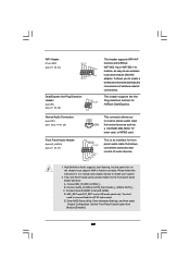
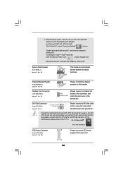
.... Set the Front Panel Control option from [Auto] to receive stereo audio input CD1 from sound sources such as below: A. This header supports the Hot Plug detection function for front panel audio cable that allows convenient connection and control of wireless network connectivity. Front Panel Audio Header (9-...GND1 D0-D0+ USB+5V_1 PME# DeskExpress Hot Plug Detection Header (5-pin IR1) (see p.11 No. 24) IRTX +5VSB Hotplug# 1 GND IRRX This header supports WiFi+AP function with ASRock WiFi-802.11g or WiFi-802.11n module, an easy-to-use AC'97 audio panel, please install it to OUT2_L.
.... Set the Front Panel Control option from [Auto] to receive stereo audio input CD1 from sound sources such as below: A. This header supports the Hot Plug detection function for front panel audio cable that allows convenient connection and control of wireless network connectivity. Front Panel Audio Header (9-...GND1 D0-D0+ USB+5V_1 PME# DeskExpress Hot Plug Detection Header (5-pin IR1) (see p.11 No. 24) IRTX +5VSB Hotplug# 1 GND IRRX This header supports WiFi+AP function with ASRock WiFi-802.11g or WiFi-802.11n module, an easy-to-use AC'97 audio panel, please install it to OUT2_L.
User Manual
Page 30
... HDLEDHDLED+ 1 SPEAKER DUMMY DUMMY +5V This header accommodates several system front panel functions. F. Click the icon on this motherboard provides 4-Pin CPU fan (Quiet Fan) support, the 3-Pin CPU fan still can work successfully even without the fan speed control function. If you plan to connect the 3-Pin CPU fan to...
... HDLEDHDLED+ 1 SPEAKER DUMMY DUMMY +5V This header accommodates several system front panel functions. F. Click the icon on this motherboard provides 4-Pin CPU fan (Quiet Fan) support, the 3-Pin CPU fan still can work successfully even without the fan speed control function. If you plan to connect the 3-Pin CPU fan to...

User Manual
Page 33
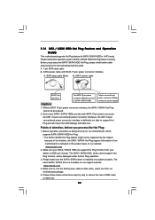
...still keeps the convenience of Hot Plug feature. If you to 400Mb/ s. NOTE: 1. How to the eSATAII ports while the system is supported with eSATAII interface, you to 3000Mb/s, which is up to enjoy the SATAII function provided by the I/O of opening your chassis to exchange ... function in the near future, eSATAII will replace USB 2.0 and IEEE 1394 to 3.0Gb/s, and the convenient mobility like USB. This motherboard supports eSATAII interface, the external SATAII specification. If you can insert or remove your eSATAII devices to 42 for external interface. 2.12 eSATAII Interface...
...still keeps the convenience of Hot Plug feature. If you to 400Mb/ s. NOTE: 1. How to the eSATAII ports while the system is supported with eSATAII interface, you to 3000Mb/s, which is up to enjoy the SATAII function provided by the I/O of opening your chassis to exchange ... function in the near future, eSATAII will replace USB 2.0 and IEEE 1394 to 3.0Gb/s, and the convenient mobility like USB. This motherboard supports eSATAII interface, the external SATAII specification. If you can insert or remove your eSATAII devices to 42 for external interface. 2.12 eSATAII Interface...
User Manual
Page 36
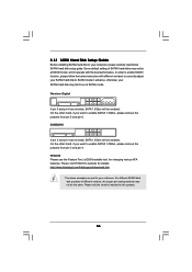
... products of SATAII hard disks may not be enabled. SAMSUNG 7531 8642 If pin 3 and pin 4 are just for details: http://www.hitachigst.com/hdd/support/download.htm The above examples are shorted, SATA 1.5Gb/s will be the same. 2.13 SATAII Hard Disk Setup Guide Before installing SATAII hard disk to...
... products of SATAII hard disks may not be enabled. SAMSUNG 7531 8642 If pin 3 and pin 4 are just for details: http://www.hitachigst.com/hdd/support/download.htm The above examples are shorted, SATA 1.5Gb/s will be the same. 2.13 SATAII Hard Disk Setup Guide Before installing SATAII hard disk to...

User Manual
Page 37
...SATAII HDDs are NOT set for the action to exchange your SATAII hard disk. 37 Intel® ICH9 south bridge chipset provides hardware support for Advanced Host controller Interface (AHCI), a new programming interface for internal storage devices. STEP 1: Install the SATA / SATAII hard disks...? You may simply plug your eSATAII devices to the eSATAII ports instead of the SATA data cable to exchange drives easily. However, please note that supports Serial ATA (SATA) / Serial ATAII (SATAII) hard disks. This section will guide you to the motherboard's SATAII connector. 2 . 1 4 Serial ...
...SATAII HDDs are NOT set for the action to exchange your SATAII hard disk. 37 Intel® ICH9 south bridge chipset provides hardware support for Advanced Host controller Interface (AHCI), a new programming interface for internal storage devices. STEP 1: Install the SATA / SATAII hard disks...? You may simply plug your eSATAII devices to the eSATAII ports instead of the SATA data cable to exchange drives easily. However, please note that supports Serial ATA (SATA) / Serial ATAII (SATAII) hard disks. This section will guide you to the motherboard's SATAII connector. 2 . 1 4 Serial ...
User Manual
Page 38
...-pin conventional power connector interfaces, the IDE 1x4-pin conventional power connector interface is available on our website: www.asrock.com 2. The latest SATA / SATAII driver is definitely not able to support Hot Plug and will be processed. 2. Make sure to use the SATA power cable & data cable, which ...be damaged under the Hot Plug operation. 3. Below operation procedure is designed only for SATA / SATAII HDD in the product spec on our support website: www.asrock.com 4. Please read below instructions step by the chipset because of its limitation, the SATA / SATAII Hot Plug...
...-pin conventional power connector interfaces, the IDE 1x4-pin conventional power connector interface is available on our website: www.asrock.com 2. The latest SATA / SATAII driver is definitely not able to support Hot Plug and will be processed. 2. Make sure to use the SATA power cable & data cable, which ...be damaged under the Hot Plug operation. 3. Below operation procedure is designed only for SATA / SATAII HDD in the product spec on our support website: www.asrock.com 4. Please read below instructions step by the chipset because of its limitation, the SATA / SATAII Hot Plug...


