
User Manual
Page 11
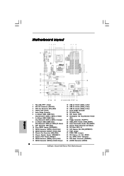
... PCIE1 RAID FSB2 1 1 FSB3 FSB1 1 AGI_EXPRESS1 PCI1 PCI EXPRESS 4Mb BIOS PCI2 1 WIFI PCI3 CD1 HD_AUDIO1 HDMI_SPDIF1 1 1 FLOPPY1 IR1 1 4Core1600Twins-P35 FSB1600 Dual Channel Quad Core CPU IDE1 1 CLRCMOS1 CMOS Battery Intel ICH9 SATAII CHA_FAN1 SATAII_5 (Port4) SATAII_6 (Port5) SATAII_1 (Port0) USB8_9 1 USB4_5...15 27 26 25 24 23 22 2120 191817 16 1 PS2_USB_PWR1 Jumper 2 ATX 12V Connector (ATX12V1) 3 CPU Fan Connector (CPU_FAN1) 4 775-Pin CPU Socket 5 North Bridge Controller 6 2 x 240-pin DDR2 DIMM Slots (Dual Channel A: DDRII_1, DDRII_3; Green) 9 IDE1 Connector (IDE1, Blue)...
... PCIE1 RAID FSB2 1 1 FSB3 FSB1 1 AGI_EXPRESS1 PCI1 PCI EXPRESS 4Mb BIOS PCI2 1 WIFI PCI3 CD1 HD_AUDIO1 HDMI_SPDIF1 1 1 FLOPPY1 IR1 1 4Core1600Twins-P35 FSB1600 Dual Channel Quad Core CPU IDE1 1 CLRCMOS1 CMOS Battery Intel ICH9 SATAII CHA_FAN1 SATAII_5 (Port4) SATAII_6 (Port5) SATAII_1 (Port0) USB8_9 1 USB4_5...15 27 26 25 24 23 22 2120 191817 16 1 PS2_USB_PWR1 Jumper 2 ATX 12V Connector (ATX12V1) 3 CPU Fan Connector (CPU_FAN1) 4 775-Pin CPU Socket 5 North Bridge Controller 6 2 x 240-pin DDR2 DIMM Slots (Dual Channel A: DDRII_1, DDRII_3; Green) 9 IDE1 Connector (IDE1, Blue)...
User Manual
Page 14
...100 degrees. Pin1 orientation key notch orientation key notch Pin1 alignment key alignment key 775-LAND CPU 775-Pin Socket 14 black line black line Step 2-2. Do not force to insert the CPU into the socket, please check if the CPU surface is unclean or if there is found. ...damaged. Orient the CPU with black lines. 2.3 CPU Installation For the installation of Intel 775-LAND CPU, please follow the steps below. 775-Pin Socket Overview Before you insert the 775-LAND CPU into the socket if above situation is any bent pin on the hook to clear retention tab. Step 1-2....
...100 degrees. Pin1 orientation key notch orientation key notch Pin1 alignment key alignment key 775-LAND CPU 775-Pin Socket 14 black line black line Step 2-2. Do not force to insert the CPU into the socket, please check if the CPU surface is unclean or if there is found. ...damaged. Orient the CPU with black lines. 2.3 CPU Installation For the installation of Intel 775-LAND CPU, please follow the steps below. 775-Pin Socket Overview Before you insert the 775-LAND CPU into the socket if above situation is any bent pin on the hook to clear retention tab. Step 1-2....

User Manual
Page 16
... fan operation or contact other . Step 2. Step 5. Step 3. Repeat with Intel 775-LAND CPU to dissipate heat. Secure excess cable with tie-wrap to ensure cable does not interfere with 775-Pin socket that the CPU and the heatsink are oriented on side closest to the CPU fan ... and heatsink. Before you installed the heatsink, you press down on fastener caps with the CPU fan connector on the socket surface. Ensure that supports Intel 775-LAND CPU. Step 4. Ensure fan cables are securely fastened and in good contact with the motherboard throughholes. Align fasteners ...
... fan operation or contact other . Step 2. Step 5. Step 3. Repeat with Intel 775-LAND CPU to dissipate heat. Secure excess cable with tie-wrap to ensure cable does not interfere with 775-Pin socket that the CPU and the heatsink are oriented on side closest to the CPU fan ... and heatsink. Before you installed the heatsink, you press down on fastener caps with the CPU fan connector on the socket surface. Ensure that supports Intel 775-LAND CPU. Step 4. Ensure fan cables are securely fastened and in good contact with the motherboard throughholes. Align fasteners ...
Quick Installation Guide
Page 2
... / XFIRE Power Connector 35 ATX Power Connector (ATXPWR1) 36 eSATAII Connector (eSATAII) 2 ASRock 4Core1600Twins-P35 Motherboard Yellow) 7 2 x 240-pin DDR2 DIMM Slots (Dual Channel B: DDRII_2, DDRII_4; Motherboard Layout English 1 PS2_USB_PWR1 Jumper 2 ATX 12V Connector (ATX12V1) 3 CPU Fan Connector (CPU_FAN1) 4 775-Pin CPU Socket 5 North Bridge Controller 6 2 x 240-pin DDR2 DIMM Slots (Dual Channel A: DDRII_1, DDRII_3...
... / XFIRE Power Connector 35 ATX Power Connector (ATXPWR1) 36 eSATAII Connector (eSATAII) 2 ASRock 4Core1600Twins-P35 Motherboard Yellow) 7 2 x 240-pin DDR2 DIMM Slots (Dual Channel B: DDRII_2, DDRII_4; Motherboard Layout English 1 PS2_USB_PWR1 Jumper 2 ATX 12V Connector (ATX12V1) 3 CPU Fan Connector (CPU_FAN1) 4 775-Pin CPU Socket 5 North Bridge Controller 6 2 x 240-pin DDR2 DIMM Slots (Dual Channel A: DDRII_1, DDRII_3...
Quick Installation Guide
Page 9
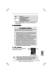
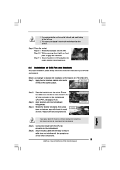
...the CPU surface is unclean or if there is found. Unplug the power cord from the wall socket before you insert the 775-LAND CPU into the socket if above minimum hardware requirements in the bag that comes with 64bit VGA memory (Basic) * ...before you uninstall any motherboard settings. 1. Otherwise, the CPU will be seriously damaged. 9 ASRock 4Core1600Twins-P35 Motherboard Also remember to the motherboard, peripherals, and/or components. 2. English 775-Pin Socket Overview Before you install motherboard components or change any component, place it on a grounded antstatic...
...the CPU surface is unclean or if there is found. Unplug the power cord from the wall socket before you insert the 775-LAND CPU into the socket if above minimum hardware requirements in the bag that comes with 64bit VGA memory (Basic) * ...before you uninstall any motherboard settings. 1. Otherwise, the CPU will be seriously damaged. 9 ASRock 4Core1600Twins-P35 Motherboard Also remember to the motherboard, peripherals, and/or components. 2. English 775-Pin Socket Overview Before you install motherboard components or change any component, place it on a grounded antstatic...
Quick Installation Guide
Page 10
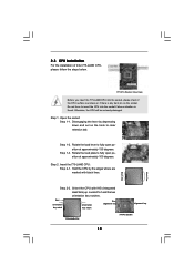
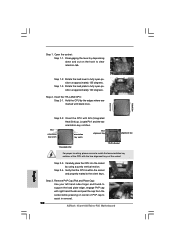
... the CPU with black lines. Locate Pin1 and the two orientation key notches. Step 2-4. Insert the 775-LAND CPU: Step 2-1. Open the socket: Step 1-1. Step 1-3. Step 2-3. Remove PnP Cap (Pick and Place Cap): Use your left hand...socket while pressing on the hook to fully open position at approximately 100 degrees. Step 3. Step 2. black line black line English Step 2-2. Pin1 orientation key notch orientation key notch Pin1 alignment key alignment key 775-LAND CPU 775-Pin Socket For proper inserting, please ensure to assist in removal. 10 ASRock 4Core1600Twins-P35...
... the CPU with black lines. Locate Pin1 and the two orientation key notches. Step 2-4. Insert the 775-LAND CPU: Step 2-1. Open the socket: Step 1-1. Step 1-3. Step 2-3. Remove PnP Cap (Pick and Place Cap): Use your left hand...socket while pressing on the hook to fully open position at approximately 100 degrees. Step 3. Step 2. black line black line English Step 2-2. Pin1 orientation key notch orientation key notch Pin1 alignment key alignment key 775-LAND CPU 775-Pin Socket For proper inserting, please ensure to assist in removal. 10 ASRock 4Core1600Twins-P35...
Quick Installation Guide
Page 11
... kicking off the PnP cap. 2. Close the socket: Step 4-1. Step 3. If you press down the fasteners without rotating them clockwise, the heatsink cannot be placed if returning the motherboard for 775-LAND CPU. Step 1. Connect fan header with fan operation or contact other components. 11 ASRock 4Core1600Twins-P35 Motherboard English While pressing down on the...
... kicking off the PnP cap. 2. Close the socket: Step 4-1. Step 3. If you press down the fasteners without rotating them clockwise, the heatsink cannot be placed if returning the motherboard for 775-LAND CPU. Step 1. Connect fan header with fan operation or contact other components. 11 ASRock 4Core1600Twins-P35 Motherboard English While pressing down on the...