
User Manual
Page 15
... fasteners. Step 3. Align fasteners with the CPU fan connector on the motherboard (CPU_FAN1, see page 10, No. 3). Step 5. Then connect the CPU fan to the instruction manuals of the heatsink for 775-LAND CPU. For proper installation, please kindly refer to the CPU_FAN connector (CPU_FAN1, see page 10, No. 3). Connect fan...
... fasteners. Step 3. Align fasteners with the CPU fan connector on the motherboard (CPU_FAN1, see page 10, No. 3). Step 5. Then connect the CPU fan to the instruction manuals of the heatsink for 775-LAND CPU. For proper installation, please kindly refer to the CPU_FAN connector (CPU_FAN1, see page 10, No. 3). Connect fan...

User Manual
Page 19
Placing jumper caps over these headers and connectors. FDD connector (33-pin FLOPPY1) (see p.10 No. 19) Pin1 FLOPPY1 the red-striped side to the instruction of the power supply. 19 Primary IDE connector (Blue) (39-pin IDE1, see p.10, No. 11) SATAII_1 SATAII_4 SATAII_2 These Serial ATAII (SATAII) connectors support ...
Placing jumper caps over these headers and connectors. FDD connector (33-pin FLOPPY1) (see p.10 No. 19) Pin1 FLOPPY1 the red-striped side to the instruction of the power supply. 19 Primary IDE connector (Blue) (39-pin IDE1, see p.10, No. 11) SATAII_1 SATAII_4 SATAII_2 These Serial ATAII (SATAII) connectors support ...

User Manual
Page 20
... Utility. Enter Advanced Settings, and then select Chipset Configuration. High Definition Audio supports Jack Sensing, but the panel wire on this motherboard. Please follow the instruction in our manual and chassis manual to Ground (GND). If you to receive stereo audio input from [Auto] to OUT2_L. Each USB 2.0 header can support...
... Utility. Enter Advanced Settings, and then select Chipset Configuration. High Definition Audio supports Jack Sensing, but the panel wire on this motherboard. Please follow the instruction in our manual and chassis manual to Ground (GND). If you to receive stereo audio input from [Auto] to OUT2_L. Each USB 2.0 header can support...

User Manual
Page 23
... 3.0Gb/s, please remove the jumpers from pin 5 and pin 6. HITACHI Please use the Feature Tool, a DOS-bootable tool, for your computer, please carefully read below instruction with different vendors to correctly adjust your SATAII hard disk may not be enabled. Some default setting of different vendors, the jumper pin setting methods...
... 3.0Gb/s, please remove the jumpers from pin 5 and pin 6. HITACHI Please use the Feature Tool, a DOS-bootable tool, for your computer, please carefully read below instruction with different vendors to correctly adjust your SATAII hard disk may not be enabled. Some default setting of different vendors, the jumper pin setting methods...

User Manual
Page 28
... the current CPU does not support CPU Thermal Throttling. No-Excute Memory Protection No-Execution (NX) Memory Protection Technology is supported through the native processor instructions HLT and MWAIT and requires no hardware support from overheated. Please note that enabling this item to boot legacy OSes that cannot support CPUs with...
... the current CPU does not support CPU Thermal Throttling. No-Excute Memory Protection No-Execution (NX) Memory Protection Technology is supported through the native processor instructions HLT and MWAIT and requires no hardware support from overheated. Please note that enabling this item to boot legacy OSes that cannot support CPUs with...

User Manual
Page 33
... 1, SATA 3, IDE 1], or [IDE 1, SATA 2, SATA 4] when the installed device is used. We will use the "Primary IDE Master" as the example in the following instruction. 33 Likewise, if it is set to [SATA 1, SATA 3, IDE 1], then SATAII_2, SATAII_4 will not work . If it is set the IDE configuration for the...
... 1, SATA 3, IDE 1], or [IDE 1, SATA 2, SATA 4] when the installed device is used. We will use the "Primary IDE Master" as the example in the following instruction. 33 Likewise, if it is set to [SATA 1, SATA 3, IDE 1], then SATAII_2, SATAII_4 will not work . If it is set the IDE configuration for the...
Quick Installation Guide
Page 11
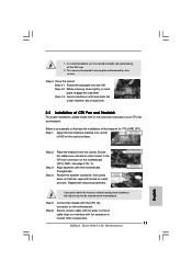
... motherboard for 775-LAND CPU. Step 4-2. Place the heatsink onto the socket. Close the socket: Step 4-1. Connect fan header with thumb to the instruction manuals of IHS on the motherboard (CPU_FAN1, see page 2, No. 3). Step 2. It is an example to the CPU fan connector on the socket... thermal interface material onto center of your CPU fan and heatsink. Step 3. Align fasteners with fan operation or contact other components. 11 ASRock 2Core1066-2.13G Motherboard English Step 6. Secure excess cable with tie-wrap to handle and avoid kicking off the PnP cap. 2.
... motherboard for 775-LAND CPU. Step 4-2. Place the heatsink onto the socket. Close the socket: Step 4-1. Connect fan header with thumb to the instruction manuals of IHS on the motherboard (CPU_FAN1, see page 2, No. 3). Step 2. It is an example to the CPU fan connector on the socket... thermal interface material onto center of your CPU fan and heatsink. Step 3. Align fasteners with fan operation or contact other components. 11 ASRock 2Core1066-2.13G Motherboard English Step 6. Secure excess cable with tie-wrap to handle and avoid kicking off the PnP cap. 2.
Quick Installation Guide
Page 15
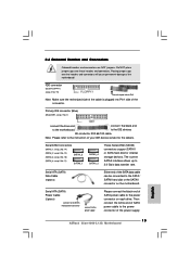
...NOT place jumper caps over the headers and connectors will cause permanent damage of the motherboard! The current SATAII interface allows up to the instruction of the connector. Primary IDE connector (Blue) (39-pin IDE1, see p.2 No. 7) connect the blue end to the motherboard connect...plugged into Pin1 side of your IDE device vendor for internal storage devices. Then connect the white end of the power supply. 15 ASRock 2Core1066-2.13G Motherboard English Placing jumper caps over these headers and connectors. Serial ATA (SATA) Power Cable (Optional) connect to the SATA HDD...
...NOT place jumper caps over the headers and connectors will cause permanent damage of the motherboard! The current SATAII interface allows up to the instruction of the connector. Primary IDE connector (Blue) (39-pin IDE1, see p.2 No. 7) connect the blue end to the motherboard connect...plugged into Pin1 side of your IDE device vendor for internal storage devices. Then connect the white end of the power supply. 15 ASRock 2Core1066-2.13G Motherboard English Placing jumper caps over these headers and connectors. Serial ATA (SATA) Power Cable (Optional) connect to the SATA HDD...

Quick Installation Guide
Page 16
Each USB 2.0 header can support two USB 2.0 ports. This connector allows you use AC'97 audio panel, please install it to [Enabled]. 16 ASRock 2Core1066-2.13G Motherboard English Connect Ground (GND) to MIC2_L. E. If you to receive stereo audio input CD1 from [Auto] to the front panel audio header... the chassis must support HDA to OUT2_L. Connect Audio_R (RIN) to OUT2_R and Audio_L (LIN) to function correctly. Please follow the instruction in our manual and chassis manual to connect them for AC'97 audio panel. You don't need to install your system. 2.
Each USB 2.0 header can support two USB 2.0 ports. This connector allows you use AC'97 audio panel, please install it to [Enabled]. 16 ASRock 2Core1066-2.13G Motherboard English Connect Ground (GND) to MIC2_L. E. If you to receive stereo audio input CD1 from [Auto] to the front panel audio header... the chassis must support HDA to OUT2_L. Connect Audio_R (RIN) to OUT2_R and Audio_L (LIN) to function correctly. Please follow the instruction in our manual and chassis manual to connect them for AC'97 audio panel. You don't need to install your system. 2.

Quick Installation Guide
Page 19
... run at SATAII mode, which operate with different vendors to correctly adjust your computer, please carefully read below instruction with the best performance. Please visit the vendors' website for the updates. 19 ASRock 2Core1066-2.13G Motherboard English For different SATAII hard disk products of SATAII hard disks may not be enabled. Some default setting...
... run at SATAII mode, which operate with different vendors to correctly adjust your computer, please carefully read below instruction with the best performance. Please visit the vendors' website for the updates. 19 ASRock 2Core1066-2.13G Motherboard English For different SATAII hard disk products of SATAII hard disks may not be enabled. Some default setting...