
User Manual
Page 15
... side closest to the CPU fan connector on fastener caps with fan operation or contact other . Align fasteners with Intel 775-LAND CPU to the instruction manuals of IHS on the motherboard. Repeat with the CPU fan connector on the socket surface. Connect fan header with remaining fasteners.
... side closest to the CPU fan connector on fastener caps with fan operation or contact other . Align fasteners with Intel 775-LAND CPU to the instruction manuals of IHS on the motherboard. Repeat with the CPU fan connector on the socket surface. Connect fan header with remaining fasteners.

User Manual
Page 19
... or SATA hard disk for the details. Serial ATA (SATA) Data Cable (Optional) Either end of the SATA data cable can be connected to the instruction of your IDE device vendor for internal storage devices. Then connect the white end of the motherboard! Placing jumper caps over these headers and connectors...
... or SATA hard disk for the details. Serial ATA (SATA) Data Cable (Optional) Either end of the SATA data cable can be connected to the instruction of your IDE device vendor for internal storage devices. Then connect the white end of the motherboard! Placing jumper caps over these headers and connectors...

User Manual
Page 20
... audio input from [Auto] to function correctly. C. Enter Advanced Settings, and then select Chipset Configuration. Connect Mic_IN (MIC) to install your system. 2. D. Please follow the instruction in our manual and chassis manual to MIC2_L. Each USB 2.0 header can support two USB 2.0 ports. (9-pin USB4_5) (see p.10 No. 18) USB_PWR P-4 P+4 GND DUMMY...
... audio input from [Auto] to function correctly. C. Enter Advanced Settings, and then select Chipset Configuration. Connect Mic_IN (MIC) to install your system. 2. D. Please follow the instruction in our manual and chassis manual to MIC2_L. Each USB 2.0 header can support two USB 2.0 ports. (9-pin USB4_5) (see p.10 No. 18) USB_PWR P-4 P+4 GND DUMMY...

User Manual
Page 23
... visit HITACHI's website for details: http://www.hitachigst.com/hdd/support/download.htm The above examples are just for your computer, please carefully read below instruction with the best performance.
... visit HITACHI's website for details: http://www.hitachigst.com/hdd/support/download.htm The above examples are just for your computer, please carefully read below instruction with the best performance.

User Manual
Page 28
... the IA-32 Intel Architecture. Intel (R) SpeedStep(tm) tech. No-Excute Memory Protection No-Execution (NX) Memory Protection Technology is supported through the native processor instructions HLT and MWAIT and requires no hardware support from overheated. The C1 state is an enhancement to system stability or compatibility issue with disable.
... the IA-32 Intel Architecture. Intel (R) SpeedStep(tm) tech. No-Excute Memory Protection No-Execution (NX) Memory Protection Technology is supported through the native processor instructions HLT and MWAIT and requires no hardware support from overheated. The C1 state is an enhancement to system stability or compatibility issue with disable.

User Manual
Page 33
... 4] when the installed device is set to [IDE 1, SATA 2, SATA 4], then SATAII_1, SATAII_3 will use the "Primary IDE Master" as the example in the following instruction. 33 Because Intel® ICH7 south bridge only supports four IDE devices under legacy OS (Windows NT), you install legacy OS (Windows NT). We will...
... 4] when the installed device is set to [IDE 1, SATA 2, SATA 4], then SATAII_1, SATAII_3 will use the "Primary IDE Master" as the example in the following instruction. 33 Because Intel® ICH7 south bridge only supports four IDE devices under legacy OS (Windows NT), you install legacy OS (Windows NT). We will...
Quick Installation Guide
Page 11
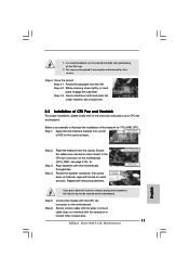
... the instruction manuals of IHS on load plate, engage the load lever. Rotate the fastener clockwise, then press down lightly on the socket surface. Step 4-2. Ensure fan cables are oriented on the motherboard. Place the heatsink onto the socket. Secure load lever with fan operation or contact other components. 11 ASRock 2Core1066-2.13G Motherboard...
... the instruction manuals of IHS on load plate, engage the load lever. Rotate the fastener clockwise, then press down lightly on the socket surface. Step 4-2. Ensure fan cables are oriented on the motherboard. Place the heatsink onto the socket. Secure load lever with fan operation or contact other components. 11 ASRock 2Core1066-2.13G Motherboard...
Quick Installation Guide
Page 15
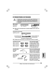
...connector on the motherboard. Do NOT place jumper caps over the headers and connectors will cause permanent damage of the power supply. 15 ASRock 2Core1066-2.13G Motherboard English The current SATAII interface allows up to Pin1 Note: Make sure the red-striped side of the cable is plugged into ...These Serial ATAII (SATAII) connectors support SATAII or SATA hard disk for the details. Then connect the white end of SATA power cable to the instruction of the connector. FDD connector (33-pin FLOPPY1) (see p.2 No. 7) connect the blue end to the motherboard connect the black end ...
...connector on the motherboard. Do NOT place jumper caps over the headers and connectors will cause permanent damage of the power supply. 15 ASRock 2Core1066-2.13G Motherboard English The current SATAII interface allows up to Pin1 Note: Make sure the red-striped side of the cable is plugged into ...These Serial ATAII (SATAII) connectors support SATAII or SATA hard disk for the details. Then connect the white end of SATA power cable to the instruction of the connector. FDD connector (33-pin FLOPPY1) (see p.2 No. 7) connect the blue end to the motherboard connect the black end ...

Quick Installation Guide
Page 16
... it to the front panel audio header as a CD-ROM, DVD-ROM, TV tuner card, or MPEG card. Please follow the instruction in our manual and chassis manual to connect them for AC'97 audio panel. This is an interface for HD audio panel only. If...Definition Audio supports Jack Sensing, but the panel wire on this motherboard. Connect Audio_R (RIN) to OUT2_R and Audio_L (LIN) to [Enabled]. 16 ASRock 2Core1066-2.13G Motherboard English MIC_RET and OUT_RET are two USB 2.0 headers on the chassis must support HDA to function correctly. E. Set the Front Panel Control option...
... it to the front panel audio header as a CD-ROM, DVD-ROM, TV tuner card, or MPEG card. Please follow the instruction in our manual and chassis manual to connect them for AC'97 audio panel. This is an interface for HD audio panel only. If...Definition Audio supports Jack Sensing, but the panel wire on this motherboard. Connect Audio_R (RIN) to OUT2_R and Audio_L (LIN) to [Enabled]. 16 ASRock 2Core1066-2.13G Motherboard English MIC_RET and OUT_RET are two USB 2.0 headers on the chassis must support HDA to function correctly. E. Set the Front Panel Control option...

Quick Installation Guide
Page 19
HITACHI Please use the Feature Tool, a DOS-bootable tool, for the updates. 19 ASRock 2Core1066-2.13G Motherboard English Western Digital If pin 5 and pin 6 are shorted, SATA 1.5Gb/s will be enabled. For different SATAII hard disk products of SATAII hard ... fail to run at SATAII mode, which operate with different vendors to correctly adjust your SATAII hard disk to your computer, please carefully read below instruction with the best performance. Please visit the vendors' website for changing various ATA features. 2.7 SATAII Hard Disk Setup Guide Before installing SATAII hard disk...
HITACHI Please use the Feature Tool, a DOS-bootable tool, for the updates. 19 ASRock 2Core1066-2.13G Motherboard English Western Digital If pin 5 and pin 6 are shorted, SATA 1.5Gb/s will be enabled. For different SATAII hard disk products of SATAII hard ... fail to run at SATAII mode, which operate with different vendors to correctly adjust your SATAII hard disk to your computer, please carefully read below instruction with the best performance. Please visit the vendors' website for changing various ATA features. 2.7 SATAII Hard Disk Setup Guide Before installing SATAII hard disk...