Installation Guide
Page 1
Switch 7700 Installation Guide Version 3.0 3C16850 7-slot Starter Kit 3C16852 8-slot Starter Kit 3C16870 4-slot Starter Kit and associated modules http://www.3com.com/ Part No. 10014180 Document Number: DUA1685-0AA02 Published November 2004
Switch 7700 Installation Guide Version 3.0 3C16850 7-slot Starter Kit 3C16852 8-slot Starter Kit 3C16870 4-slot Starter Kit and associated modules http://www.3com.com/ Part No. 10014180 Document Number: DUA1685-0AA02 Published November 2004

Installation Guide
Page 2
...basis. If you in conjunction with only such rights as translation, transformation, or adaptation) without written permission from 3Com Corporation. 3Com Corporation reserves the right to revise this documentation without obligation on paper that all waste conforms to : Establishing ...countries, licensed exclusively through X/Open Company, Ltd. Maximizing the recyclable and reusable content of safely. Unless otherwise indicated, 3Com registered trademarks are associated. Microsoft, MS-DOS, Windows, and Windows NT are registered trademarks of this User Guide. Software...
...basis. If you in conjunction with only such rights as translation, transformation, or adaptation) without written permission from 3Com Corporation. 3Com Corporation reserves the right to revise this documentation without obligation on paper that all waste conforms to : Establishing ...countries, licensed exclusively through X/Open Company, Ltd. Maximizing the recyclable and reusable content of safely. Unless otherwise indicated, 3Com registered trademarks are associated. Microsoft, MS-DOS, Windows, and Windows NT are registered trademarks of this User Guide. Software...
Installation Guide
Page 3
CONTENTS ABOUT THIS GUIDE Conventions 7 Related Documentation 8 SWITCH 7700 COMPONENTS Switch Chassis 9 Switch Backplane 9 Fabric Module 10 Submodule Slot 11 Reset Button 11 Fixed Ports 11 Module LEDs 12 Power LEDs 13 Fan LED 13 Fabric 32 Submodules ... 19 20-Port 10/100/1000BASE-T Module 20 20-Port 1000BASE-X-SFP Module 22 1-Port 10GBASE-R-XENPAK Module 23 Power Module 24 Fan Assembly 25 Switch 7700 Specifications 26 Switch 7700 Software Features 27 INSTALLING THE SWITCH 7700 Preparing to Install 29 General Safety Recommendations 29 Electrical Safety 30 Moving the...
CONTENTS ABOUT THIS GUIDE Conventions 7 Related Documentation 8 SWITCH 7700 COMPONENTS Switch Chassis 9 Switch Backplane 9 Fabric Module 10 Submodule Slot 11 Reset Button 11 Fixed Ports 11 Module LEDs 12 Power LEDs 13 Fan LED 13 Fabric 32 Submodules ... 19 20-Port 10/100/1000BASE-T Module 20 20-Port 1000BASE-X-SFP Module 22 1-Port 10GBASE-R-XENPAK Module 23 Power Module 24 Fan Assembly 25 Switch 7700 Specifications 26 Switch 7700 Software Features 27 INSTALLING THE SWITCH 7700 Preparing to Install 29 General Safety Recommendations 29 Electrical Safety 30 Moving the...
Installation Guide
Page 4
... AUX Cable 36 Connecting Module Cables 37 Installing Cabling 38 Bench-Mounted Switch 38 Rack-Mounted Switch 38 Cable Binding 38 Post-installation Checklist 39 CONFIGURING THE SWITCH 7700 Configuring the Switch 7700 and a Local Terminal 41 Setting Terminal Parameters 41 Booting the Switch 7700 44 Powering up and Booting 45 MAINTAINING SOFTWARE Upgrading Software...
... AUX Cable 36 Connecting Module Cables 37 Installing Cabling 38 Bench-Mounted Switch 38 Rack-Mounted Switch 38 Cable Binding 38 Post-installation Checklist 39 CONFIGURING THE SWITCH 7700 Configuring the Switch 7700 and a Local Terminal 41 Setting Terminal Parameters 41 Booting the Switch 7700 44 Powering up and Booting 45 MAINTAINING SOFTWARE Upgrading Software...

Installation Guide
Page 5
... No information is displayed on the terminal 61 The displayed characters are illegible 61 Troubleshooting Power 61 Troubleshooting the Fan 62 Troubleshooting the Modules 62 SWITCH 7700 CABLES Console Cable 63 AUX Cable 63 Electrical Port Connector 64 Optical Fiber Cable Connectors 65 OBTAINING SUPPORT FOR YOUR...
... No information is displayed on the terminal 61 The displayed characters are illegible 61 Troubleshooting Power 61 Troubleshooting the Fan 62 Troubleshooting the Modules 62 SWITCH 7700 CABLES Console Cable 63 AUX Cable 63 Electrical Port Connector 64 Optical Fiber Cable Connectors 65 OBTAINING SUPPORT FOR YOUR...
Installation Guide
Page 7
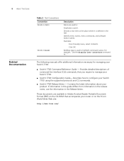
... responsible for the latest updates to software and product documentation: http://www.3com.com Table 1 lists icon conventions that alerts you to potential personal injury. Always download the Release Notes for your switch. Table 1 Notice Icons Icon Notice Type Description Information note Information that ...local area network (LAN) operations and familiarity with a plus sign (+), for your product from the 3Com World Wide Web site and check for configuring, using, and managing the switches. Keyboard key names If you see the word "enter" in this guide. Do not press Return...
... responsible for the latest updates to software and product documentation: http://www.3com.com Table 1 lists icon conventions that alerts you to potential personal injury. Always download the Release Notes for your switch. Table 1 Notice Icons Icon Notice Type Description Information note Information that ...local area network (LAN) operations and familiarity with a plus sign (+), for your product from the 3Com World Wide Web site and check for configuring, using, and managing the switches. Keyboard key names If you see the word "enter" in this guide. Do not press Return...
Installation Guide
Page 8
Identify menu names, menu commands, and software button names. Describes how to configure your Switch 7700. ■ Switch 7700 Configuration Guide- These documents are used to ..." Boldface type is defined in bold Description Italics are ...detailed descriptions of command line interface (CLI) commands, that accompanies your router or on the 3Com World Wide Web site: http://www.3com.com/ Contains the latest information about your Switch 7700: ■ Switch 7700 Command Reference Guide - The following manuals offer additional information necessary for managing your product...
Identify menu names, menu commands, and software button names. Describes how to configure your Switch 7700. ■ Switch 7700 Configuration Guide- These documents are used to ..." Boldface type is defined in bold Description Italics are ...detailed descriptions of command line interface (CLI) commands, that accompanies your router or on the 3Com World Wide Web site: http://www.3com.com/ Contains the latest information about your Switch 7700: ■ Switch 7700 Command Reference Guide - The following manuals offer additional information necessary for managing your product...
Installation Guide
Page 9
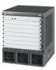
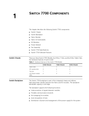
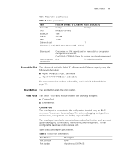
...; I/O Modules ■ Power Module ■ Fan Assembly ■ Switch 7700 Specifications ■ Switch 7700 Software Features There are three Switch 7700 Models, the 4-Slot, 7-Slot, and the 8-Slot. Table 3 Hardware Features of the Switch 7700 Models Fabric slots I/O module slots Fan slot AC Power module slots... management of the power supply for the system Table 3 lists the hardware features of each model. 1 SWITCH 7700 COMPONENTS Switch Chassis Switch Backplane The chapter describes the following functions: ■ Interconnection of signals between the Fabric and I/O modules.
...; I/O Modules ■ Power Module ■ Fan Assembly ■ Switch 7700 Specifications ■ Switch 7700 Software Features There are three Switch 7700 Models, the 4-Slot, 7-Slot, and the 8-Slot. Table 3 Hardware Features of the Switch 7700 Models Fabric slots I/O module slots Fan slot AC Power module slots... management of the power supply for the system Table 3 lists the hardware features of each model. 1 SWITCH 7700 COMPONENTS Switch Chassis Switch Backplane The chapter describes the following functions: ■ Interconnection of signals between the Fabric and I/O modules.

Installation Guide
Page 10
...LEDs 6 Power LEDs 7 I /O modules through the backplane and forwards Layer 2 and Layer 3 data ■ Manages and calculates routing ■ Performs the switch's software upgrade and system reset functions ■ Monitors system power and the fan frame Figure 1 illustrates the front panel of the Fabric 64. It has... 32 only in the 7- You can install the Fabric 64 only in a 4-slot chassis. 10 CHAPTER 1: SWITCH 7700 COMPONENTS Fabric Module There are two Fabric modules for the Switch 7700: ■ Fabric 64 (3C16857 or 3C16857R) ■ Fabric 32 (3C16872) The Fabric 64 and Fabric...
...LEDs 6 Power LEDs 7 I /O modules through the backplane and forwards Layer 2 and Layer 3 data ■ Manages and calculates routing ■ Performs the switch's software upgrade and system reset functions ■ Monitors system power and the fan frame Figure 1 illustrates the front panel of the Fabric 64. It has... 32 only in the 7- You can install the Fabric 64 only in a 4-slot chassis. 10 CHAPTER 1: SWITCH 7700 COMPONENTS Fabric Module There are two Fabric modules for the Switch 7700: ■ Fabric 64 (3C16857 or 3C16857R) ■ Fabric 32 (3C16872) The Fabric 64 and Fabric...
Installation Guide
Page 11
Fixed Ports The Switch 7700 Fabric module provides the following submodules: ■ 4-port 1000BASE-X-GBIC submodule ■ 4-port 10/100/1000BASE-T submodule For more information on these submodules, see "...) Submodule Slot The submodule slot in ) External ports Maximum power consumption One console port that supports local and remote dial-up configuration management of the switch. Table 5 lists console port specifications. You can configure the baud rate on page 13. One 10BASE-T/100BASE-TX port for system debugging, configuration, maintenance, management...
Fixed Ports The Switch 7700 Fabric module provides the following submodules: ■ 4-port 1000BASE-X-GBIC submodule ■ 4-port 10/100/1000BASE-T submodule For more information on these submodules, see "...) Submodule Slot The submodule slot in ) External ports Maximum power consumption One console port that supports local and remote dial-up configuration management of the switch. Table 5 lists console port specifications. You can configure the baud rate on page 13. One 10BASE-T/100BASE-TX port for system debugging, configuration, maintenance, management...

Installation Guide
Page 12
... and debugging. Table 6 lists Ethernet port specifications. Green - Green flashing - The module failed or has not been inserted. 12 CHAPTER 1: SWITCH 7700 COMPONENTS Table 5 Console Port Specifications (continued) Specification Baud rate Transmission distance Services Description 9600 bps (by default) 15 m (45 ft)... 10 Mbps, half/full duplex 100 Mbps, half/full duplex MDIX Category-5 twisted pair for transmission within 100 m (300 ft) Switch software upgrade and network management See "Electrical Port Connector" on the Fabric is connected to manage the system remotely. The line is...
... and debugging. Table 6 lists Ethernet port specifications. Green - Green flashing - The module failed or has not been inserted. 12 CHAPTER 1: SWITCH 7700 COMPONENTS Table 5 Console Port Specifications (continued) Specification Baud rate Transmission distance Services Description 9600 bps (by default) 15 m (45 ft)... 10 Mbps, half/full duplex 100 Mbps, half/full duplex MDIX Category-5 twisted pair for transmission within 100 m (300 ft) Switch software upgrade and network management See "Electrical Port Connector" on the Fabric is connected to manage the system remotely. The line is...

Installation Guide
Page 13
The corresponding power module is not working or has not been installed. The fan is not working normally or has not been installed. FAIL Green - Off - Fabric 32 Submodules 13 Power LEDs PWR1, PWR2, and PWR3 LEDs show the status of the power modules, as described in Table 9. The corresponding power module is working or has not been installed. The fan is not working normally. Figure 3 4-Port 1000BASE-X-GBIC Submodule 3C16874 12 Ethernet GBIC port 2 Ethernet GBIC port LED Table 11 describes the 4-port 1000BASE-X-GBIC submodule LEDs. Off - The link is working ....
The corresponding power module is not working or has not been installed. The fan is not working normally or has not been installed. FAIL Green - Off - Fabric 32 Submodules 13 Power LEDs PWR1, PWR2, and PWR3 LEDs show the status of the power modules, as described in Table 9. The corresponding power module is working or has not been installed. The fan is not working normally. Figure 3 4-Port 1000BASE-X-GBIC Submodule 3C16874 12 Ethernet GBIC port 2 Ethernet GBIC port LED Table 11 describes the 4-port 1000BASE-X-GBIC submodule LEDs. Off - The link is working ....
Installation Guide
Page 14
... is not operating. Green flashing - Table 14 4-Port 10/100/1000BASE-T Submodule Specifications Specification Connector type Number of the 4-port 1000BASE-X-GBIC submodule. 14 CHAPTER 1: SWITCH 7700 COMPONENTS Table 12 lists the specifications for each of ports Port speed Cable and maximum transmission distance Description RJ-45 4 1000 Mbps full duplex...
... is not operating. Green flashing - Table 14 4-Port 10/100/1000BASE-T Submodule Specifications Specification Connector type Number of the 4-port 1000BASE-X-GBIC submodule. 14 CHAPTER 1: SWITCH 7700 COMPONENTS Table 12 lists the specifications for each of ports Port speed Cable and maximum transmission distance Description RJ-45 4 1000 Mbps full duplex...

Installation Guide
Page 15
...; You must select I/O module port cables that are the same and any combination of the 48-port 10/100BASE-T Auto-sensing FE module. I /O Modules The Switch 7700 provides slots for an illustration of the 48-Port 10/100BASE-T Auto-sensing FE module 12 I /O Modules 15 See "Electrical Port Connector" on page...
...; You must select I/O module port cables that are the same and any combination of the 48-port 10/100BASE-T Auto-sensing FE module. I /O Modules The Switch 7700 provides slots for an illustration of the 48-Port 10/100BASE-T Auto-sensing FE module 12 I /O Modules 15 See "Electrical Port Connector" on page...

Installation Guide
Page 16
... 8-port 1000BASE-X GE module provides 8 external GBIC module ports. The following modules are 2 100-ohm Category-5 twisted pairs up to 100 m (300 ft). 16 CHAPTER 1: SWITCH 7700 COMPONENTS 1 Ethernet port 2 Ethernet port LED Each 100 Mbps Ethernet port has a green LED, indicating LINK/ACTIVE status. The port is connected Off - The...
... 8-port 1000BASE-X GE module provides 8 external GBIC module ports. The following modules are 2 100-ohm Category-5 twisted pairs up to 100 m (300 ft). 16 CHAPTER 1: SWITCH 7700 COMPONENTS 1 Ethernet port 2 Ethernet port LED Each 100 Mbps Ethernet port has a green LED, indicating LINK/ACTIVE status. The port is connected Off - The...

Installation Guide
Page 17
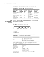
Figure 7 8-Port 1000BASE-X GE Module I/O Modules 17 3C16858 Every GBIC port has a LED, as shown in Figure 8. No data is being transmitted Green flashing - Table 18 GBIC Module Port Cables GBIC Module Type 3CGBIC91 3CGBIC92 3CGBIC97 Central Wave Length 850 nm 1550 nm 1550 nm Table 19 describes the specifications of the supported 8GBIC modules are described inTable 18. The link is connected ACT Off - The link is not connected Green - Table 19 Specifications for each of the 8-port 1000BASE-X GE module. Data is being transmitted or received The cables for the 8-Port...
Figure 7 8-Port 1000BASE-X GE Module I/O Modules 17 3C16858 Every GBIC port has a LED, as shown in Figure 8. No data is being transmitted Green flashing - Table 18 GBIC Module Port Cables GBIC Module Type 3CGBIC91 3CGBIC92 3CGBIC97 Central Wave Length 850 nm 1550 nm 1550 nm Table 19 describes the specifications of the supported 8GBIC modules are described inTable 18. The link is connected ACT Off - The link is not connected Green - Table 19 Specifications for each of the 8-port 1000BASE-X GE module. Data is being transmitted or received The cables for the 8-Port...

Installation Guide
Page 18
... 10/100/1000BASE-T GE Module The 8-port 10/100/1000BASE-T GE module provides 8 external 10/100/1000 Mbps auto-sensing Ethernet electrical ports. 18 CHAPTER 1: SWITCH 7700 COMPONENTS Table 19 Specifications for the 8-Port 1000BASE-X GE Module (continued) Specification BootROM SDRAM Dimensions (L x W) Maximum power consumption Number of the 8-Port 10/100...
... 10/100/1000BASE-T GE Module The 8-port 10/100/1000BASE-T GE module provides 8 external 10/100/1000 Mbps auto-sensing Ethernet electrical ports. 18 CHAPTER 1: SWITCH 7700 COMPONENTS Table 19 Specifications for the 8-Port 1000BASE-X GE Module (continued) Specification BootROM SDRAM Dimensions (L x W) Maximum power consumption Number of the 8-Port 10/100...

Installation Guide
Page 19
Data is being transmitted or received Specifications of ports 8 Port transmission speed 10 Mbps, half/full duplex 100 Mbps, half/full duplex 1000 Mbps, full duplex Cables and maximum transmission distance 4 100-ohm Category-5 non-shielded twisted pairs up to 100 m (300 ft). Figure 11 24-Port 100BASE-FX MMF FE Module The link is not connected Green - The link is connected ACT Off - Table 21 Specifications for the 8-Port 10/100/1000BASE-T GE Module Specification Description CPU MPC850 BootROM 512 Kb SDRAM 64 MB Dimensions (L x W) 366.7 x 340 mm (14.5 x 13.4...
Data is being transmitted or received Specifications of ports 8 Port transmission speed 10 Mbps, half/full duplex 100 Mbps, half/full duplex 1000 Mbps, full duplex Cables and maximum transmission distance 4 100-ohm Category-5 non-shielded twisted pairs up to 100 m (300 ft). Figure 11 24-Port 100BASE-FX MMF FE Module The link is not connected Green - The link is connected ACT Off - Table 21 Specifications for the 8-Port 10/100/1000BASE-T GE Module Specification Description CPU MPC850 BootROM 512 Kb SDRAM 64 MB Dimensions (L x W) 366.7 x 340 mm (14.5 x 13.4...

Installation Guide
Page 20
.../1000BASE-T Module. Table 22 24-Port 100BASE-FX MMF FE Module LEDs LED LINK/ACT Description Green - Green flashing - Data is not connected. 20 CHAPTER 1: SWITCH 7700 COMPONENTS Each 100 Mbps optical port has a green LED, as shown in ) 55 W MT-RJ 24 100 Mbps, full-duplex 62.5/125 µm multi...
.../1000BASE-T Module. Table 22 24-Port 100BASE-FX MMF FE Module LEDs LED LINK/ACT Description Green - Green flashing - Data is not connected. 20 CHAPTER 1: SWITCH 7700 COMPONENTS Each 100 Mbps optical port has a green LED, as shown in ) 55 W MT-RJ 24 100 Mbps, full-duplex 62.5/125 µm multi...

Installation Guide
Page 21
On - Green flashing - The port is not operating. The port is operating. Figure 14 Front Panel of ports Transmission rate Description MPC8241LZU200 512 KB 64 MB 366.7 x 340 mm (14.5 x 13.4 in) 45 W RJ-45 20 10 Mbps half/full duplex 100 Mbps half/full duplex 1000 Mbps full duplex Table 25 Specifications for the 20-Port 10/100/1000BASE-T Module Specification CPU BootROM SDRAM Dimensions (L x W) Power consumption Connector Number of the 20-Port 10/100/1000BASE-T Module 3C16863 12 1 Ethernet port 2 Ethernet port LED Table 24 describes the 20-port 10/100/1000BASE-T module LEDs....
On - Green flashing - The port is not operating. The port is operating. Figure 14 Front Panel of ports Transmission rate Description MPC8241LZU200 512 KB 64 MB 366.7 x 340 mm (14.5 x 13.4 in) 45 W RJ-45 20 10 Mbps half/full duplex 100 Mbps half/full duplex 1000 Mbps full duplex Table 25 Specifications for the 20-Port 10/100/1000BASE-T Module Specification CPU BootROM SDRAM Dimensions (L x W) Power consumption Connector Number of the 20-Port 10/100/1000BASE-T Module 3C16863 12 1 Ethernet port 2 Ethernet port LED Table 24 describes the 20-port 10/100/1000BASE-T module LEDs....