Installation Guide
Page 3
... GUIDE Conventions 7 Related Documentation 8 SWITCH 7700 COMPONENTS Switch Chassis 9 Switch Backplane 9 Fabric Module 10 Submodule Slot 11 Reset Button 11 Fixed Ports 11 Module LEDs 12 Power LEDs 13 Fan LED 13 Fabric 32 Submodules 13 4-Port 1000BASE-X-GBIC Submodule 13 4-Port 10/100/1000BASE-T Submodule 14 I/O Modules 15 48-port 10/100BASE-T Auto-sensing FE Module 15 8-port 1000BASE-X GE Module 16 8-port 10/100/1000BASE-T GE Module 18 24-port 100BASE-FX MMF FE Module...
... GUIDE Conventions 7 Related Documentation 8 SWITCH 7700 COMPONENTS Switch Chassis 9 Switch Backplane 9 Fabric Module 10 Submodule Slot 11 Reset Button 11 Fixed Ports 11 Module LEDs 12 Power LEDs 13 Fan LED 13 Fabric 32 Submodules 13 4-Port 1000BASE-X-GBIC Submodule 13 4-Port 10/100/1000BASE-T Submodule 14 I/O Modules 15 48-port 10/100BASE-T Auto-sensing FE Module 15 8-port 1000BASE-X GE Module 16 8-port 10/100/1000BASE-T GE Module 18 24-port 100BASE-FX MMF FE Module...
Installation Guide
Page 4
...-Mounted Switch 38 Rack-Mounted Switch 38 Cable Binding 38 Post-installation Checklist 39 CONFIGURING THE SWITCH 7700 Configuring the Switch 7700 and a Local Terminal 41 Setting Terminal Parameters 41 Booting the Switch 7700 44 Powering up and Booting 45 MAINTAINING SOFTWARE Upgrading Software 47 Upgrading the Software Image 47 Upgrading an 8-Slot Chassis 47 Upgrading Software with FTP 48 Upgrading Software Using The BOOT Menu 49 Upgrading Software Using Xmodem 53 Upgrading Software Using TFTP 55 Lost Passwords 55 Using the BOOT Menu 55 MAINTAINING HARDWARE Replacing a Power Module 57 Removing...
...-Mounted Switch 38 Rack-Mounted Switch 38 Cable Binding 38 Post-installation Checklist 39 CONFIGURING THE SWITCH 7700 Configuring the Switch 7700 and a Local Terminal 41 Setting Terminal Parameters 41 Booting the Switch 7700 44 Powering up and Booting 45 MAINTAINING SOFTWARE Upgrading Software 47 Upgrading the Software Image 47 Upgrading an 8-Slot Chassis 47 Upgrading Software with FTP 48 Upgrading Software Using The BOOT Menu 49 Upgrading Software Using Xmodem 53 Upgrading Software Using TFTP 55 Lost Passwords 55 Using the BOOT Menu 55 MAINTAINING HARDWARE Replacing a Power Module 57 Removing...
Installation Guide
Page 7
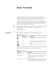
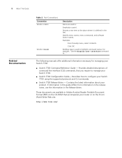
... press Return or Enter when an instruction simply says "type." ABOUT THIS GUIDE Conventions This guide describes the 3Com® Switch 7700 and how to install hardware, configure and boot software, and maintain software and hardware. This guide is intended for Qualified Service personnel who are used throughout this guide. This guide also provides troubleshooting and support information for configuring, using, and managing the switches. Table 1 Notice Icons Icon Notice Type Description Information note Information that...
... press Return or Enter when an instruction simply says "type." ABOUT THIS GUIDE Conventions This guide describes the 3Com® Switch 7700 and how to install hardware, configure and boot software, and maintain software and hardware. This guide is intended for Qualified Service personnel who are used throughout this guide. This guide also provides troubleshooting and support information for configuring, using, and managing the switches. Table 1 Notice Icons Icon Notice Type Description Information note Information that...
Installation Guide
Page 8
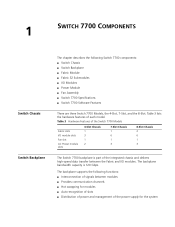
... in Adobe Acrobat Reader Portable Document Format (PDF) on the CD-ROM that you require to manage your router or on the 3Com World Wide Web site: http://www.3com.com/ For example, "Use the display user-interface command to : Emphasize a point. Identify menu names, menu commands, and software button names. The following manuals offer additional information necessary for managing your Switch 7700: ■ Switch 7700 Command Reference Guide - Denote a new term at...
... in Adobe Acrobat Reader Portable Document Format (PDF) on the CD-ROM that you require to manage your router or on the 3Com World Wide Web site: http://www.3com.com/ For example, "Use the display user-interface command to : Emphasize a point. Identify menu names, menu commands, and software button names. The following manuals offer additional information necessary for managing your Switch 7700: ■ Switch 7700 Command Reference Guide - Denote a new term at...
Installation Guide
Page 9
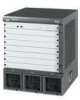
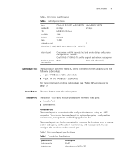
... I /O Modules ■ Power Module ■ Fan Assembly ■ Switch 7700 Specifications ■ Switch 7700 Software Features There are three Switch 7700 Models, the 4-Slot, 7-Slot, and the 8-Slot. Table 3 lists the hardware features of the power supply for modules ■ Auto-recognition of slots ■ Distribution of power and management of each model. The backplane supports the following Switch 7700 components: ■ Switch Chassis ■ Switch Backplane ■ Fabric Module ■ Fabric 32 Submodules ■ I /O modules. Table 3 Hardware...
... I /O Modules ■ Power Module ■ Fan Assembly ■ Switch 7700 Specifications ■ Switch 7700 Software Features There are three Switch 7700 Models, the 4-Slot, 7-Slot, and the 8-Slot. Table 3 lists the hardware features of the power supply for modules ■ Auto-recognition of slots ■ Distribution of power and management of each model. The backplane supports the following Switch 7700 components: ■ Switch Chassis ■ Switch Backplane ■ Fabric Module ■ Fabric 32 Submodules ■ I /O modules. Table 3 Hardware...

Installation Guide
Page 10
... 3C16872 1 1 Submodule slot 2 Console port 3 Ethernet port 4 Ethernet port LEDs 5 Fan LEDs 6 Power LEDs 7 I /O module LEDs 56 7 Figure 2 illustrates the front panel of the Fabric 32. You can install the Fabric 32 only in the 7- It has the following functions: ■ Connects the I/O modules through the backplane and forwards Layer 2 and Layer 3 data ■ Manages and calculates routing ■ Performs the switch's software upgrade and system reset functions ■ Monitors system power and the fan frame Figure 1 illustrates the front...
... 3C16872 1 1 Submodule slot 2 Console port 3 Ethernet port 4 Ethernet port LEDs 5 Fan LEDs 6 Power LEDs 7 I /O module LEDs 56 7 Figure 2 illustrates the front panel of the Fabric 32. You can install the Fabric 32 only in the 7- It has the following functions: ■ Connects the I/O modules through the backplane and forwards Layer 2 and Layer 3 data ■ Manages and calculates routing ■ Performs the switch's software upgrade and system reset functions ■ Monitors system power and the fan frame Figure 1 illustrates the front...
Installation Guide
Page 11
... 256 MB Flash 16 MB Submodule slot 1 Dimensions (L x W) 366.7 mm x 340 mm (14.5 x 13.5 in the Fabric 32 offers extended Ethernet capacity using an RJ-45 connector. Fixed Ports The Switch 7700 Fabric module provides the following fixed ports: ■ Console Port ■ Ethernet Port Console Port The console port is connected to a modem for system debugging, configuration, maintenance, management, and loading application files. Fabric Module 11 Table 4 lists Fabric specifications. Reset Button The reset button resets the...
... 256 MB Flash 16 MB Submodule slot 1 Dimensions (L x W) 366.7 mm x 340 mm (14.5 x 13.5 in the Fabric 32 offers extended Ethernet capacity using an RJ-45 connector. Fixed Ports The Switch 7700 Fabric module provides the following fixed ports: ■ Console Port ■ Ethernet Port Console Port The console port is connected to a modem for system debugging, configuration, maintenance, management, and loading application files. Fabric Module 11 Table 4 lists Fabric specifications. Reset Button The reset button resets the...

Installation Guide
Page 12
...remote connection) Ethernet Port The Ethernet port on page 64 for an illustration of the I /O Module LEDs LED RUN ALM Status description Green or off - Table 6 lists Ethernet port specifications. Green flashing - The module failed or has not been inserted. The module is connected to a computer using an RJ-45 connector. 12 CHAPTER 1: SWITCH 7700 COMPONENTS Table 5 Console Port Specifications (continued) Specification Baud rate Transmission distance Services Description 9600 bps (by default) 15 m (45 ft) Connects with character terminal Connects with local or remote PC serial port...
...remote connection) Ethernet Port The Ethernet port on page 64 for an illustration of the I /O Module LEDs LED RUN ALM Status description Green or off - Table 6 lists Ethernet port specifications. Green flashing - The module failed or has not been inserted. The module is connected to a computer using an RJ-45 connector. 12 CHAPTER 1: SWITCH 7700 COMPONENTS Table 5 Console Port Specifications (continued) Specification Baud rate Transmission distance Services Description 9600 bps (by default) 15 m (45 ft) Connects with character terminal Connects with local or remote PC serial port...

Installation Guide
Page 13
... GE full-duplex Ethernet Submodule GBIC ports. FAIL Green - The fan is being transmitted. Data is working normally or has not been installed. Table 10 Fan LEDs LED Description OK Green - The corresponding power module is not working or has not been installed. The fan is not working . Figure 3 4-Port 1000BASE-X-GBIC Submodule 3C16874 12 Ethernet GBIC port 2 Ethernet GBIC port LED Table 11 describes the 4-port 1000BASE-X-GBIC submodule LEDs. Table 9 Power LEDs LED Description OK Green - Fan LED Fan LEDs show the status of the fan frame, as described...
... GE full-duplex Ethernet Submodule GBIC ports. FAIL Green - The fan is being transmitted. Data is working normally or has not been installed. Table 10 Fan LEDs LED Description OK Green - The corresponding power module is not working or has not been installed. The fan is not working . Figure 3 4-Port 1000BASE-X-GBIC Submodule 3C16874 12 Ethernet GBIC port 2 Ethernet GBIC port LED Table 11 describes the 4-port 1000BASE-X-GBIC submodule LEDs. Table 9 Power LEDs LED Description OK Green - Fan LED Fan LEDs show the status of the fan frame, as described...

Installation Guide
Page 16
... 2 100-ohm Category-5 twisted pairs up to 100 m (300 ft). 16 CHAPTER 1: SWITCH 7700 COMPONENTS 1 Ethernet port 2 Ethernet port LED Each 100 Mbps Ethernet port has a green LED, indicating LINK/ACTIVE status. Data is used for the 48-Port 10/100BASE-T Auto-sensing FE Module Specification CPU BootROM SDRAM Dimensions (L X W) Maximum power consumption Connector Number of ports Port transmission speed Cables and maximum transmission distance Compliance Description MPC850 512 KB 64 MB 366.7 x 340 mm...
... 2 100-ohm Category-5 twisted pairs up to 100 m (300 ft). 16 CHAPTER 1: SWITCH 7700 COMPONENTS 1 Ethernet port 2 Ethernet port LED Each 100 Mbps Ethernet port has a green LED, indicating LINK/ACTIVE status. Data is used for the 48-Port 10/100BASE-T Auto-sensing FE Module Specification CPU BootROM SDRAM Dimensions (L X W) Maximum power consumption Connector Number of ports Port transmission speed Cables and maximum transmission distance Compliance Description MPC850 512 KB 64 MB 366.7 x 340 mm...

Installation Guide
Page 22
....3ab IEEE 802.3 IEEE 802.3u IEEE 802.3x IEEE 802.1D IEEE 802.1Q 20-Port 1000BASE-X-SFP The 20-port 1000BASE-X-SFP module provides 20 1000 BASE-X full duplex ports Module and uses an SFP cable. Figure 15 20-Port 1000BASE-X-SFP Module Figure 16 illustrates the front panel of the 20-Port 1000BASE-X-SFP Module 3C16862 1 2 1 Ethernet port 2 Ethernet port LED Table 26 describes the 20-port 1000BASE-X-SFP module LEDs. Green flashing - The port is operating.
....3ab IEEE 802.3 IEEE 802.3u IEEE 802.3x IEEE 802.1D IEEE 802.1Q 20-Port 1000BASE-X-SFP The 20-port 1000BASE-X-SFP module provides 20 1000 BASE-X full duplex ports Module and uses an SFP cable. Figure 15 20-Port 1000BASE-X-SFP Module Figure 16 illustrates the front panel of the 20-Port 1000BASE-X-SFP Module 3C16862 1 2 1 Ethernet port 2 Ethernet port LED Table 26 describes the 20-port 1000BASE-X-SFP module LEDs. Green flashing - The port is operating.

Installation Guide
Page 27
....1D standard and supporting port lock. The granularity of the Switch 7700. Table 33 Switch 7700 Software Features Service Wire speed Layer 2 switching Port auto-negotiation Switching mode MAC address table STP/RSTP Traffic control Link aggregation VLAN Broadcast storm suppression Network protocol IP address table IP routing Multicast AAA and Security Reliability QoS Support Switching capacity of 64Gbps Packet forwarding rate at 48Mpps Wire speed forwarding (with IEEE 802.1x Local authentication and RADIUS authentication User hierarchical management and password protection ACL, L2/L3/L4...
....1D standard and supporting port lock. The granularity of the Switch 7700. Table 33 Switch 7700 Software Features Service Wire speed Layer 2 switching Port auto-negotiation Switching mode MAC address table STP/RSTP Traffic control Link aggregation VLAN Broadcast storm suppression Network protocol IP address table IP routing Multicast AAA and Security Reliability QoS Support Switching capacity of 64Gbps Packet forwarding rate at 48Mpps Wire speed forwarding (with IEEE 802.1x Local authentication and RADIUS authentication User hierarchical management and password protection ACL, L2/L3/L4...

Installation Guide
Page 36
... the console cable to the serial port of the PC or the terminal where the switch is used to the Switch 7700. Always wear the antistatic wrist strap when installing the fan. Installing Cables This section describes how to connect console and AUX cables to plug into the console port of the virtual modem. See "AUX Cable" on the virtual modem. Connecting the AUX An AUX cable is to be configured. 2 Connect...
... the console cable to the serial port of the PC or the terminal where the switch is used to the Switch 7700. Always wear the antistatic wrist strap when installing the fan. Installing Cables This section describes how to connect console and AUX cables to plug into the console port of the virtual modem. See "AUX Cable" on the virtual modem. Connecting the AUX An AUX cable is to be configured. 2 Connect...

Installation Guide
Page 48
... control connection about to I. [ftp]get sw7700003.app 200 PORT command successful. 150 File status OK ; Actual IP addresses and filenames will return to primary status. 48 CHAPTER 4: MAINTAINING SOFTWARE To upgrade an 8-slot Switch 7700 with FTP: 1 Upgrade the Fabric in Slot0 using the procedure in Upgrading Software with super-user privileges. 2 From the SW7700 command line, transfer the file from the FTP server to the system, using the ftp command...
... control connection about to I. [ftp]get sw7700003.app 200 PORT command successful. 150 File status OK ; Actual IP addresses and filenames will return to primary status. 48 CHAPTER 4: MAINTAINING SOFTWARE To upgrade an 8-slot Switch 7700 with FTP: 1 Upgrade the Fabric in Slot0 using the procedure in Upgrading Software with super-user privileges. 2 From the SW7700 command line, transfer the file from the FTP server to the system, using the ftp command...

Installation Guide
Page 49
..., Version 4.00 * * * Copyright© 2001-2005 by default), the system will access the BOOT Menu: CAUTION: While using the switch, keep in this chapter. If you want to access the BOOT Menu after this procedure, you must have a network connection to flash Upgrading Software To perform this , you must reboot the switch. 2 Enter the BootROM password. LOCAL_SDRAM Address lines Selftest OK! Boot Menu 1: Download application file to the Using The BOOT Menu management port on...
..., Version 4.00 * * * Copyright© 2001-2005 by default), the system will access the BOOT Menu: CAUTION: While using the switch, keep in this chapter. If you want to access the BOOT Menu after this procedure, you must have a network connection to flash Upgrading Software To perform this , you must reboot the switch. 2 Enter the BootROM password. LOCAL_SDRAM Address lines Selftest OK! Boot Menu 1: Download application file to the Using The BOOT Menu management port on...

Installation Guide
Page 53
... the software upgrade. 4 Press Enter. Press enter key when ready. After passing the negotiation, the sending program begins to select a download speed of check; Set XMODEM protocol parameter 0. The terminal displays the following information: Download baudrate is supported, normally 10 times. However, if you use the display boot command to send the next packet. The secondary boot image name cannot be displayed. Xmodem also supports two types of...
... the software upgrade. 4 Press Enter. Press enter key when ready. After passing the negotiation, the sending program begins to select a download speed of check; Set XMODEM protocol parameter 0. The terminal displays the following information: Download baudrate is supported, normally 10 times. However, if you use the display boot command to send the next packet. The secondary boot image name cannot be displayed. Xmodem also supports two types of...

Installation Guide
Page 55
... the TFTP server is set up according to the manufacturer's instructions and that there is a connection between clients and servers. boot boot-loader sw7700003.app The specified file will reboot the system. Now begin to download file from the server, and sends the acknowledgement to boot the system from the server. Using the BOOT Menu After you power on the CDROM with super-user privileges. 2 From the Switch 7700 command line (in user view), TFTP...
... the TFTP server is set up according to the manufacturer's instructions and that there is a connection between clients and servers. boot boot-loader sw7700003.app The specified file will reboot the system. Now begin to download file from the server, and sends the acknowledgement to boot the system from the server. Using the BOOT Menu After you power on the CDROM with super-user privileges. 2 From the Switch 7700 command line (in user view), TFTP...

Installation Guide
Page 56
... 60X_SDRAM Data lines Selftest OK! 60X_SDRAM Address lines Selftest OK! 60X_SDRAM fast selftest OK! Press Ctrl+B to boot 3: Display all files in flash 4: Delete file from flash 5: Modify bootrom password 0: Reboot Enter your choice(0-5): CAUTION: While using the switch, please keep in mind the modified BOOTROM password. Press Ctrl+B. After entering the correct password (no password is booting * * • SW 7700 BOOTROM, Version 4.00 * * * Copyright© 2001-2005 by default), the...
... 60X_SDRAM Data lines Selftest OK! 60X_SDRAM Address lines Selftest OK! 60X_SDRAM fast selftest OK! Press Ctrl+B to boot 3: Display all files in flash 4: Delete file from flash 5: Modify bootrom password 0: Reboot Enter your choice(0-5): CAUTION: While using the switch, please keep in mind the modified BOOTROM password. Press Ctrl+B. After entering the correct password (no password is booting * * • SW 7700 BOOTROM, Version 4.00 * * * Copyright© 2001-2005 by default), the...

Installation Guide
Page 67
...://www.3com.com/. A link to software downloads can include 24x7 telephone technical support, software upgrades, onsite assistance or advance hardware replacement. First time users must apply for the version of software initially purchased with minimal disruption to your network. This diagnostic software is available at http://eSupport.3com.com/. In order to access these Software Updates you must first register your networking projects. Expert assessment and implementation services are based on the 3Com web site...
...://www.3com.com/. A link to software downloads can include 24x7 telephone technical support, software upgrades, onsite assistance or advance hardware replacement. First time users must apply for the version of software initially purchased with minimal disruption to your network. This diagnostic software is available at http://eSupport.3com.com/. In order to access these Software Updates you must first register your networking projects. Expert assessment and implementation services are based on the 3Com web site...
Installation Guide
Page 68
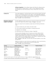
... SUPPORT FOR YOUR SWITCH Software Upgrades are correct at the time of publication. You will be returned to 3Com for assistance, please have the following e-mail: apr_technical_support@3com.com Or request a repair authorization number (RMA) by fax using the following information ready: ■ Product model name, part number, and serial number ■ A list of support telephone numbers posted on the 3Com web site at http://eSupport.3com.com/. In order to 3Com, without authorization numbers clearly...
... SUPPORT FOR YOUR SWITCH Software Upgrades are correct at the time of publication. You will be returned to 3Com for assistance, please have the following e-mail: apr_technical_support@3com.com Or request a repair authorization number (RMA) by fax using the following information ready: ■ Product model name, part number, and serial number ■ A list of support telephone numbers posted on the 3Com web site at http://eSupport.3com.com/. In order to 3Com, without authorization numbers clearly...


