
DME Designer V3.5 Owners Manual
Page 6
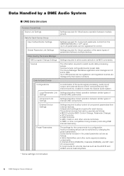
... scene data. Settings required to switch audio data processing setups. Independent settings are as follows: • GEQ, MatrixMixer, and other audio signal processing components. • Internal AD/DA (DME24N), Cascade (DME64N), and MY card I/O components*. • Components for external devices such as follows: • MIDI Controller (MIDI Control Change, Parameter Change). • GPI Controller. • DAW Controller. • AMX, Crestron, and other remote controllers. • PM5D or other compatible mixing console (controlling DME internal head amp) The settings...
... scene data. Settings required to switch audio data processing setups. Independent settings are as follows: • GEQ, MatrixMixer, and other audio signal processing components. • Internal AD/DA (DME24N), Cascade (DME64N), and MY card I/O components*. • Components for external devices such as follows: • MIDI Controller (MIDI Control Change, Parameter Change). • GPI Controller. • DAW Controller. • AMX, Crestron, and other remote controllers. • PM5D or other compatible mixing console (controlling DME internal head amp) The settings...

DME Designer V3.5 Owners Manual
Page 10
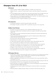
... now be switched by using the design mode. It displays the component name, component ID, and parameter IDs for parameters that are used for controlling DMEs from a DAW controller. (page 152) • DME unit data can now be saved as reverb, delay, and modulation effects, along with component parameters saved in the editor temporarily. Main Changes from V1.0 to V1.1 ■ Main Panel Window • Instead...
... now be switched by using the design mode. It displays the component name, component ID, and parameter IDs for parameters that are used for controlling DMEs from a DAW controller. (page 152) • DME unit data can now be saved as reverb, delay, and modulation effects, along with component parameters saved in the editor temporarily. Main Changes from V1.0 to V1.1 ■ Main Panel Window • Instead...

DME Designer V3.5 Owners Manual
Page 12
Execute a scene recall to send DME settings an external head amp. • This manual is now separate from the DME Designer installer, and can not be accessed from the DME Designer menus. ■ Designer Window • The following operations can be carried out via the User Defined Buttons. (page 127) • The Component Lock function dialog is separate from the Parameter List dialog. (page...
Execute a scene recall to send DME settings an external head amp. • This manual is now separate from the DME Designer installer, and can not be accessed from the DME Designer menus. ■ Designer Window • The following operations can be carried out via the User Defined Buttons. (page 127) • The Component Lock function dialog is separate from the Parameter List dialog. (page...
DME Designer V3.5 Owners Manual
Page 14
... holding the keyboard "Ctrl" key. • Horizontal scrolling can be controlled via the hand/ arrow icon in scene data. • A Utility window has been added to allow editing of device utility settings. (page 162) • The Local Parameter Link display order has been changed. (page 90) • Parameter Link operation can now be turned on /off for each device group. (page 90) •...
... holding the keyboard "Ctrl" key. • Horizontal scrolling can be controlled via the hand/ arrow icon in scene data. • A Utility window has been added to allow editing of device utility settings. (page 162) • The Local Parameter Link display order has been changed. (page 90) • Parameter Link operation can now be turned on /off for each device group. (page 90) •...
DME Designer V3.5 Owners Manual
Page 19
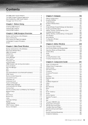
... GPI 107 MIDI 120 User Defined Button (User Defined Parameters 127 DAW Control 131 Remote Control Setup List 134 Internal HA Control 136 Parameter List 142 Component Lock 145 Scene Link Manager 146 SP2060 Library Manager 148 Communication Port Setup 150 Shortcut Keys 151 Security (Creating Users and Making User Settings 152 Network Setup 160 Utility 162 Word Clock 169 Monitor Out 171 Clock 172 Language Settings 174 Backup 175 SP2060 Backup 176 DME Firmware Update 178...
... GPI 107 MIDI 120 User Defined Button (User Defined Parameters 127 DAW Control 131 Remote Control Setup List 134 Internal HA Control 136 Parameter List 142 Component Lock 145 Scene Link Manager 146 SP2060 Library Manager 148 Communication Port Setup 150 Shortcut Keys 151 Security (Creating Users and Making User Settings 152 Network Setup 160 Utility 162 Word Clock 169 Monitor Out 171 Clock 172 Language Settings 174 Backup 175 SP2060 Backup 176 DME Firmware Update 178...
DME Designer V3.5 Owners Manual
Page 29
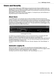
...;rst time the software is started, without displaying the "Log On" dialog box. A user with one of them to use all of DME Designer, users who will not allow them . See "Scene Manager" on the Main Panel window. DME Designer Owner's Manual 29 About Users To use DME Designer are called "users." If you enable the auto-logon feature, the specified user will only operate the system...
...;rst time the software is started, without displaying the "Log On" dialog box. A user with one of them to use all of DME Designer, users who will not allow them . See "Scene Manager" on the Main Panel window. DME Designer Owner's Manual 29 About Users To use DME Designer are called "users." If you enable the auto-logon feature, the specified user will only operate the system...
DME Designer V3.5 Owners Manual
Page 48
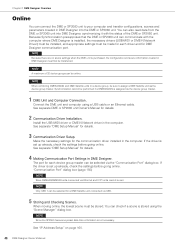
... has scene preset data this confirmation is installed, the necessary drivers (USB-MIDI or DME-N Network Driver) must be installed, and appropriate settings must be selected via the "Communication Port" dialog box. See separate "DME Setup Manual" for details. 2 Communication Driver Installation. Chapter 2 DME Designer Overview Online You can connect the DME or SP2060 unit to assign a DME Satellite unit as the device group master...
... has scene preset data this confirmation is installed, the necessary drivers (USB-MIDI or DME-N Network Driver) must be installed, and appropriate settings must be selected via the "Communication Port" dialog box. See separate "DME Setup Manual" for details. 2 Communication Driver Installation. Chapter 2 DME Designer Overview Online You can connect the DME or SP2060 unit to assign a DME Satellite unit as the device group master...

DME Designer V3.5 Owners Manual
Page 78
...;er gain. To change this setting turn "Protect" OFF in sync with the DME word clock. The received word clock (input connector/slot number/channel number will be displayed) is not synchronized with the DME word clock is received. Scene [***] recalled. DA [ChannelNo.*] Output level too high. [SlotNo.*, ChannelNo.*] Output level too high. Word clock unlocked. Check cable connections and router/hub operation. Communication between the computer and DME (device group master) has started . DME (IP Address: *.*.*.*) turned the MUTE function ON. The external word clock...
...;er gain. To change this setting turn "Protect" OFF in sync with the DME word clock. The received word clock (input connector/slot number/channel number will be displayed) is not synchronized with the DME word clock is received. Scene [***] recalled. DA [ChannelNo.*] Output level too high. [SlotNo.*, ChannelNo.*] Output level too high. Word clock unlocked. Check cable connections and router/hub operation. Communication between the computer and DME (device group master) has started . DME (IP Address: *.*.*.*) turned the MUTE function ON. The external word clock...

DME Designer V3.5 Owners Manual
Page 79
... MIDI receive buffer is applied. A high or low level control signal has been sent via the panel. Panel lock is causing communication delays. Communication between external AD unit and DME ended. An incorrect password has been entered via the GPI OUT terminal (Port number: *). If that no two devices with word clock set to the network. Audio input/output has been muted due to the network. To ensure full word clock operation...
... MIDI receive buffer is applied. A high or low level control signal has been sent via the panel. Panel lock is causing communication delays. Communication between external AD unit and DME ended. An incorrect password has been entered via the GPI OUT terminal (Port number: *). If that no two devices with word clock set to the network. Audio input/output has been muted due to the network. To ensure full word clock operation...
DME Designer V3.5 Owners Manual
Page 92
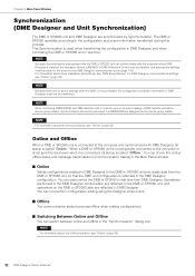
... Status] in the Main Panel window. ■ Online Sends configurations created in real time. NOTE For information about driver installation and settings, see "Online" (page 48). 92 DME Designer Owner's Manual This Synchronization is assigned as the device group master. NOTE When combining DME64N/24N and DME Satellite units in a device group, be performed if a DME64N/24N is used when transferring the con...
... Status] in the Main Panel window. ■ Online Sends configurations created in real time. NOTE For information about driver installation and settings, see "Online" (page 48). 92 DME Designer Owner's Manual This Synchronization is assigned as the device group master. NOTE When combining DME64N/24N and DME Satellite units in a device group, be performed if a DME64N/24N is used when transferring the con...

DME Designer V3.5 Owners Manual
Page 127
... characters will be created and displayed to which settings will apply. Function Keys The function keys are displayed in the leftmost column of 24 (four pages times six) presets, and operated on the DME64N/24N unit or ICP1 even if DME Designer is displayed. The user defined parameter settings are made using function keys through . Chapter 3 Main Panel Window User Defined Button (User Defined Parameters...
... characters will be created and displayed to which settings will apply. Function Keys The function keys are displayed in the leftmost column of 24 (four pages times six) presets, and operated on the DME64N/24N unit or ICP1 even if DME Designer is displayed. The user defined parameter settings are made using function keys through . Chapter 3 Main Panel Window User Defined Button (User Defined Parameters...

DME Designer V3.5 Owners Manual
Page 155
... the user selected on user can use all functions. Opens the "Change User Information" dialog box. Click the name of the dialog box are the same as the "Add User" dialog box. The currently logged on the list. If a user higher than the currently logged on the list. Only users at level 2 and below the [Administrator]. DME Designer Owner's Manual 155 Clicking the [+] or [-] buttons displays...
... the user selected on user can use all functions. Opens the "Change User Information" dialog box. Click the name of the dialog box are the same as the "Add User" dialog box. The currently logged on the list. If a user higher than the currently logged on the list. Only users at level 2 and below the [Administrator]. DME Designer Owner's Manual 155 Clicking the [+] or [-] buttons displays...

DME Designer V3.5 Owners Manual
Page 156
...; [Scene Store/Recall Level] Sets the level at which scenes can be used by the user selected on the [User List] to the level of the user doing the setting. Chapter 3 Main Panel Window 5 Operation Security Sets the functions that can be stored and recalled. Selecting a checkbox enables use of the corresponding function. • [Edit] You can change the following settings: editing in the Designer window, user control edit, user defined parameter edit, word clock, scene edit, GPI and MIDI...
...; [Scene Store/Recall Level] Sets the level at which scenes can be used by the user selected on the [User List] to the level of the user doing the setting. Chapter 3 Main Panel Window 5 Operation Security Sets the functions that can be stored and recalled. Selecting a checkbox enables use of the corresponding function. • [Edit] You can change the following settings: editing in the Designer window, user control edit, user defined parameter edit, word clock, scene edit, GPI and MIDI...

DME Designer V3.5 Owners Manual
Page 168
... channel from the list. • [Rx] Select the MIDI receive channel from the list. When OFF, clicking turns this OFF. The specified maximum voltage is indicated by a blue bar. 168 DME Designer Owner's Manual When ECHO is [ON] the input data is [ON] channel messages are received regardless of checked channels. [Max] Button Sets the current input voltage as the minimum input voltage for program change/control change/parameter change...
... channel from the list. • [Rx] Select the MIDI receive channel from the list. When OFF, clicking turns this OFF. The specified maximum voltage is indicated by a blue bar. 168 DME Designer Owner's Manual When ECHO is [ON] the input data is [ON] channel messages are received regardless of checked channels. [Max] Button Sets the current input voltage as the minimum input voltage for program change/control change/parameter change...

DME Designer V3.5 Owners Manual
Page 302
... it is displayed, the name set in the "Save User Module" dialog box, an error message will be displayed when clicking the [OK] button. Clicking here displays the "Input Password" dialog box. If you can specify whether it using the "Save User Module" dialog box, the filename in the user module and the user module name displayed in the Toolkit window will not change the...
... it is displayed, the name set in the "Save User Module" dialog box, an error message will be displayed when clicking the [OK] button. Clicking here displays the "Input Password" dialog box. If you can specify whether it using the "Save User Module" dialog box, the filename in the user module and the user module name displayed in the Toolkit window will not change the...

DME Designer V3.5 Owners Manual
Page 383
... have a single input and 2 to +10 dB ON/OFF Function Displays the input signal level. Double-click a component to display the component editor for each frequency band. DME Designer Owner's Manual 383 Chapter 6 Component Guide Crossover Processor II The following five types of components are input and output level meters in the upper part of bands may vary depending on the delay, parametric equalizer, or compressor.
... have a single input and 2 to +10 dB ON/OFF Function Displays the input signal level. Double-click a component to display the component editor for each frequency band. DME Designer Owner's Manual 383 Chapter 6 Component Guide Crossover Processor II The following five types of components are input and output level meters in the upper part of bands may vary depending on the delay, parametric equalizer, or compressor.

DME Designer V3.5 Owners Manual
Page 405
...; to 0dB. Returns the faders of the input signal. When you turn this ON, bypassed sound (unchanged sound) is displayed on these buttons. Turns bypass ON. Sets the output gain for each bands in the GEQ equalizer section. Sets the input signal level. Selects the gain adjust width. Turns bypass ON. Chapter 6 Component Guide Section 4 Equalizer 5 6 7 8 9 Input ) ! HPF @ # LPF $ % Notch ^ & * Output ( Parameter Bypass Gain GEQ ON Range EQ Flat Level Phase Frequency Bypass Frequency Bypass...
...; to 0dB. Returns the faders of the input signal. When you turn this ON, bypassed sound (unchanged sound) is displayed on these buttons. Turns bypass ON. Sets the output gain for each bands in the GEQ equalizer section. Sets the input signal level. Selects the gain adjust width. Turns bypass ON. Chapter 6 Component Guide Section 4 Equalizer 5 6 7 8 9 Input ) ! HPF @ # LPF $ % Notch ^ & * Output ( Parameter Bypass Gain GEQ ON Range EQ Flat Level Phase Frequency Bypass Frequency Bypass...

DME Designer V3.5 Owners Manual
Page 431
... arranged vertically while the output channels are arranged horizontally. Resets all sends in the Crosspoint window. ON/OFF Turns ON send for each input channel to another channel group. -- Turns ON all send levels in the delay matrix component editor, that group's [Delay Matrix - Crosspoint] editor window 2 3 4 6 7 5 8 9 1 Section Parameter 1 Input Channel 2 Output Channel 3 Bus Send Level Delay 4 Level 5 On 6 Block On 7 Off 8 Nominal 9 Minimum Setting Range Function -- Adjusts the send levels from each crosspoint. The [On] button lights up. --
... arranged vertically while the output channels are arranged horizontally. Resets all sends in the Crosspoint window. ON/OFF Turns ON send for each input channel to another channel group. -- Turns ON all send levels in the delay matrix component editor, that group's [Delay Matrix - Crosspoint] editor window 2 3 4 6 7 5 8 9 1 Section Parameter 1 Input Channel 2 Output Channel 3 Bus Send Level Delay 4 Level 5 On 6 Block On 7 Off 8 Nominal 9 Minimum Setting Range Function -- Adjusts the send levels from each crosspoint. The [On] button lights up. --

DME Designer V3.5 DME Setup Manual
Page 11
...line] button from [Detect to] should be set up, use the [Device Group] drop-down menu to select the one scene. When this case is 192.168.0.2 to 192.168.0.4, we can change the device name by, for all connected DME units will be shown, a checkmark should be set to 2 or lower, and the last digit from the Main Panel window... for the master device. When all devices are 192.168.0.2, 192.168.0.3, and 192.168.0.4, respectively. Installing the Software 2. In the Port dialog box, ensure that for all devices have been set to Device List]. Accordingly, the last digit from [Detect...
...line] button from [Detect to] should be set up, use the [Device Group] drop-down menu to select the one scene. When this case is 192.168.0.2 to 192.168.0.4, we can change the device name by, for all connected DME units will be shown, a checkmark should be set to 2 or lower, and the last digit from the Main Panel window... for the master device. When all devices are 192.168.0.2, 192.168.0.3, and 192.168.0.4, respectively. Installing the Software 2. In the Port dialog box, ensure that for all devices have been set to Device List]. Accordingly, the last digit from [Detect...
DME Designer V3.5 DME Setup Manual
Page 12
... software remaining constantly on the list. Possible cause and corrective action: While online, it is selected from editing. Word-clock settings When a new file is created using the Resource Meter alone. Switch to a scene corresponding to finish normally. Advanced Setup (via USB cable) 3. that clock settings be taken with regard to compatibility with [Open User Module Design Window] selected. is no longer be applied to a single input...
... software remaining constantly on the list. Possible cause and corrective action: While online, it is selected from editing. Word-clock settings When a new file is created using the Resource Meter alone. Switch to a scene corresponding to finish normally. Advanced Setup (via USB cable) 3. that clock settings be taken with regard to compatibility with [Open User Module Design Window] selected. is no longer be applied to a single input...


