MCXSP10 Manual
Page 3
... these requirements provides a reasonable level of assurance that your authority, granted by the FCC, to use the product. 2 IMPORTANT: When connecting this product to a wall or ceiling only as an improper adjustment of other products (including amplifiers) that are covered by the operating ... or cable system is in all installation instructions. Modifications not expressly approved by Yamaha may result in wire to an antenna discharge unit, size of grounding conductors, location of antenna discharge unit, connection to the operation of other hazards. 21 Safety Check - If you can ...
... these requirements provides a reasonable level of assurance that your authority, granted by the FCC, to use the product. 2 IMPORTANT: When connecting this product to a wall or ceiling only as an improper adjustment of other products (including amplifiers) that are covered by the operating ... or cable system is in all installation instructions. Modifications not expressly approved by Yamaha may result in wire to an antenna discharge unit, size of grounding conductors, location of antenna discharge unit, connection to the operation of other hazards. 21 Safety Check - If you can ...
MCXSP10 Manual
Page 4
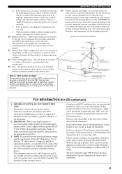
..., damage to this unit, and/or personal injury. 7 Do not plug in a safe place for future reference. 2 Install this unit rises, it is connected to a wall outlet until it is turned off. Voltages are complete. 8 Do not operate this unit. - Retain this Owner's Manual in this unit to...TROUBLESHOOTING" section on the back of plug to use this unit for any damage resulting from use force on this manual carefully. iii Contact qualified YAMAHA service personnel when any reasons. 15 When not planning to wide slot and fully insert. Use a clean, dry cloth. 12 Only voltage specified...
..., damage to this unit, and/or personal injury. 7 Do not plug in a safe place for future reference. 2 Install this unit rises, it is connected to a wall outlet until it is turned off. Voltages are complete. 8 Do not operate this unit. - Retain this Owner's Manual in this unit to...TROUBLESHOOTING" section on the back of plug to use this unit for any damage resulting from use force on this manual carefully. iii Contact qualified YAMAHA service personnel when any reasons. 15 When not planning to wide slot and fully insert. Use a clean, dry cloth. 12 Only voltage specified...
MCXSP10 Manual
Page 5
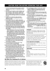
...8 Rear panel 10 PREPARATION SPEAKER SETUP 11 Speaker placement 11 Speaker connections 12 CONNECTIONS 15 Before connecting components 15 Connecting video components 16 Connecting audio components 19 Connecting the FM and AM antennas 21 Connecting the power supply cord 22 Speaker impedance setting 23 Turning on the... 97 SOUND FIELD PROGRAMS ADVANCED OPERATION ADDITIONAL INFORMATION 1 AND EUROPE MODELS ONLY) .........78 Zone 2 connections 78 Remote controlling Zone 2 79 ADDITIONAL INFORMATION EDITING SOUND FIELD PARAMETERS ......81 What is XM Satellite Radio 44 XM Satellite...
...8 Rear panel 10 PREPARATION SPEAKER SETUP 11 Speaker placement 11 Speaker connections 12 CONNECTIONS 15 Before connecting components 15 Connecting video components 16 Connecting audio components 19 Connecting the FM and AM antennas 21 Connecting the power supply cord 22 Speaker impedance setting 23 Turning on the... 97 SOUND FIELD PROGRAMS ADVANCED OPERATION ADDITIONAL INFORMATION 1 AND EUROPE MODELS ONLY) .........78 Zone 2 connections 78 Remote controlling Zone 2 79 ADDITIONAL INFORMATION EDITING SOUND FIELD PARAMETERS ......81 What is XM Satellite Radio 44 XM Satellite...
MCXSP10 Manual
Page 6
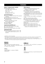
...Front: 95 W + 95 W Center: 95 W Surround: 95 W + 95 W Surround back: 95 W + 95 W Sound field features ◆ Proprietary YAMAHA technology for the creation of sound fields ◆ Dolby Digital/Dolby Digital EX decoder ◆ DTS/DTS-ES Matrix 6.1, Discrete 6.1, DTS Neo:6, DTS 96/24...shifting capability (preset editing) XM Satellite Radio ◆ XM Satellite Radio programming (using the "XM Connect and Play digital antenna accessory", sold separately) Other features ◆ YPAO: YAMAHA Parametric Room Acoustic Optimizer for automatic speaker setup ◆ 192-kHz/24-bit D/A converter ◆...
...Front: 95 W + 95 W Center: 95 W Surround: 95 W + 95 W Surround back: 95 W + 95 W Sound field features ◆ Proprietary YAMAHA technology for the creation of sound fields ◆ Dolby Digital/Dolby Digital EX decoder ◆ DTS/DTS-ES Matrix 6.1, Discrete 6.1, DTS Neo:6, DTS 96/24...shifting capability (preset editing) XM Satellite Radio ◆ XM Satellite Radio programming (using the "XM Connect and Play digital antenna accessory", sold separately) Other features ◆ YPAO: YAMAHA Parametric Room Acoustic Optimizer for automatic speaker setup ◆ 192-kHz/24-bit D/A converter ◆...
MCXSP10 Manual
Page 8
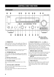
Note In standby mode, this button for use with the AUTO SETUP function (see page 24). 3 Remote control sensor Receives signals from a portable external source such as the input source. 4 Hold down this unit consumes a small amount of power in the memory. model) ZONE ... (A to E) when the unit is not in tuner mode. 7 MEMORY (MAN'L/AUTO FM) Stores a station in order to receive infrared-signals from the remote control. 2 OPTIMIZER MIC jack Use to connect and input audio signals from the supplied microphone for more than 3 seconds to the standby mode. Selects the tuning frequency...
Note In standby mode, this button for use with the AUTO SETUP function (see page 24). 3 Remote control sensor Receives signals from a portable external source such as the input source. 4 Hold down this unit consumes a small amount of power in the memory. model) ZONE ... (A to E) when the unit is not in tuner mode. 7 MEMORY (MAN'L/AUTO FM) Stores a station in order to receive infrared-signals from the remote control. 2 OPTIMIZER MIC jack Use to connect and input audio signals from the supplied microphone for more than 3 seconds to the standby mode. Selects the tuning frequency...

MCXSP10 Manual
Page 9
...front left and right headphone channels. CONTROLS AND FUNCTIONS ■ U.S.A., Canada, Australia, U.K. INTRODUCTION 0 VOLUME Controls the output level of front speakers connected to the A and/or B terminals on the rear panel each time the corresponding button is pressed. This does not affect the REC OUT level.... ZONE 2 Switches this unit's operation to or watch. A PHONES (SILENT CINEMA) jack Outputs audio signals for the type of signals received when one component is in the XM Satellite Radio mode (see page 79). All Dolby Digital and DTS audio signals are output directly from...
...front left and right headphone channels. CONTROLS AND FUNCTIONS ■ U.S.A., Canada, Australia, U.K. INTRODUCTION 0 VOLUME Controls the output level of front speakers connected to the A and/or B terminals on the rear panel each time the corresponding button is pressed. This does not affect the REC OUT level.... ZONE 2 Switches this unit's operation to or watch. A PHONES (SILENT CINEMA) jack Outputs audio signals for the type of signals received when one component is in the XM Satellite Radio mode (see page 79). All Dolby Digital and DTS audio signals are output directly from...
MCXSP10 Manual
Page 10
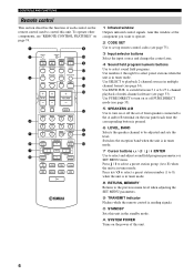
... (see page 33). A SYSTEM POWER Turns on or off PURE DIRECT mode (see "REMOTE CONTROL FEATURES" on page 74. 1 2 3 CODE SET TRANSMIT POWER TV POWER AV STANDBY CD MD/CD-R TUNER SYSTEM POWER SLEEP DVD DTV/CBL V-AUX MULTI CH IN VCR 1 DVR/VCR2 AMP TV VOL TV CH VOLUME 9 0 A B C D E 4 5 6 7 8 TV... components, see page 35). 5 SPEAKERS A/B Use to control this window at the component you want to operate. 2 CODE SET Use to set of front speakers connected to the A and/or B terminal on the rear panel each control on the remote control used to turn on or off the set up remote...
... (see page 33). A SYSTEM POWER Turns on or off PURE DIRECT mode (see "REMOTE CONTROL FEATURES" on page 74. 1 2 3 CODE SET TRANSMIT POWER TV POWER AV STANDBY CD MD/CD-R TUNER SYSTEM POWER SLEEP DVD DTV/CBL V-AUX MULTI CH IN VCR 1 DVR/VCR2 AMP TV VOL TV CH VOLUME 9 0 A B C D E 4 5 6 7 8 TV... components, see page 35). 5 SPEAKERS A/B Use to control this window at the component you want to operate. 2 CODE SET Use to set of front speakers connected to the A and/or B terminal on the rear panel each control on the remote control used to turn on or off the set up remote...

MCXSP10 Manual
Page 12
... (see page 34). C VOLUME level indication Indicates the current volume level. E STANDARD Lights up when headphones are connected. H Headphones indicator Lights up when headphones are connected and a sound field program is active (see page 31). 4 Input source indicators A cursor lights to show that...sound field program name and other information when adjusting or changing settings. 8 I HiFi DSP indicator Lights up when this unit is receiving a strong signal for an FM stereo broadcast while the AUTO indicator is reproducing PCM (Pulse Code Modulation) digital audio signals. ...
... (see page 34). C VOLUME level indication Indicates the current volume level. E STANDARD Lights up when headphones are connected. H Headphones indicator Lights up when headphones are connected and a sound field program is active (see page 31). 4 Input source indicators A cursor lights to show that...sound field program name and other information when adjusting or changing settings. 8 I HiFi DSP indicator Lights up when this unit is receiving a strong signal for an FM stereo broadcast while the AUTO indicator is reproducing PCM (Pulse Code Modulation) digital audio signals. ...

MCXSP10 Manual
Page 14
... This is a control expansion terminal for commercial use. 9 AC OUTLET(S) Use to supply power to your other models) See page 13 for connection information. See page 78 for details. and Europe models) PRESENCE speaker terminals (other A/V components (see page 22). 0 DIGITAL INPUT jacks See... REMOTE IN OUT CONTROL OUT +12V 15mA MAX. and Europe models only) These jacks output analog signals only. C PRE OUT jacks See page 20 for connection information. 6 REMOTE IN/OUT jacks (U.S.A., Canada, Australia, U.K. CONTROLS AND FUNCTIONS Rear panel 12 3 4 5 6 78 9 DIGITAL OUTPUT MD/CD-R...
... This is a control expansion terminal for commercial use. 9 AC OUTLET(S) Use to supply power to your other models) See page 13 for connection information. See page 78 for details. and Europe models) PRESENCE speaker terminals (other A/V components (see page 22). 0 DIGITAL INPUT jacks See... REMOTE IN OUT CONTROL OUT +12V 15mA MAX. and Europe models only) These jacks output analog signals only. C PRE OUT jacks See page 20 for connection information. 6 REMOTE IN/OUT jacks (U.S.A., Canada, Australia, U.K. CONTROLS AND FUNCTIONS Rear panel 12 3 4 5 6 78 9 DIGITAL OUTPUT MD/CD-R...

MCXSP10 Manual
Page 16
...10 mm (3/8") of insulation from the end of each speaker cable. 5 Tighten the knob to secure the wire. 3 4 5 Red: positive (+) Black: negative (-) ■ Connecting to PRESENCE/ZONE 2 or PRESENCE speaker terminals 2 1 3 1 Open the tab. 2 Insert one bare wire into the hole of each terminal. 3 Return the tab to ...secure the wire. ■ Banana plug connections (With the exception of U.K., Europe and Asia models) First, tighten the knob and then insert the banana plug connector into the hole in the ...
...10 mm (3/8") of insulation from the end of each speaker cable. 5 Tighten the knob to secure the wire. 3 4 5 Red: positive (+) Black: negative (-) ■ Connecting to PRESENCE/ZONE 2 or PRESENCE speaker terminals 2 1 3 1 Open the tab. 2 Insert one bare wire into the hole of each terminal. 3 Return the tab to ...secure the wire. ■ Banana plug connections (With the exception of U.K., Europe and Asia models) First, tighten the knob and then insert the banana plug connector into the hole in the ...

MCXSP10 Manual
Page 17
... ambient effects created by the DSP sound fields. model) 6 7 Front 8 speakers (B) Center speaker Right Left Front speakers (A) 9 10 Right Left Surround back speakers You can connect both surround back and presence speakers to this unit, but they do not output sound when other sound fields are selected. 13
... ambient effects created by the DSP sound fields. model) 6 7 Front 8 speakers (B) Center speaker Right Left Front speakers (A) 9 10 Right Left Surround back speakers You can connect both surround back and presence speakers to this unit, but they do not output sound when other sound fields are selected. 13

MCXSP10 Manual
Page 18
SPEAKER SETUP ■ FRONT terminals Connect one surround back speaker, connect it to the FRONT A or B terminals. ■ CENTER terminals Connect a center speaker (8) to these terminals. ■ SURROUND terminals Connect surround speakers (4, 5) to these terminals. ■ SUBWOOFER jack Connect a subwoofer with built-in amplifier (1), such as the YAMAHA Active Servo Processing Subwoofer System, to this jack. ■...
SPEAKER SETUP ■ FRONT terminals Connect one surround back speaker, connect it to the FRONT A or B terminals. ■ CENTER terminals Connect a center speaker (8) to these terminals. ■ SURROUND terminals Connect surround speakers (4, 5) to these terminals. ■ SUBWOOFER jack Connect a subwoofer with built-in amplifier (1), such as the YAMAHA Active Servo Processing Subwoofer System, to this jack. ■...
MCXSP10 Manual
Page 19
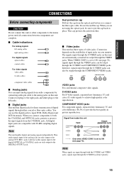
...into luminance (Y) and color (C) video signals to ON (see page 70). PREPARATION CONNECTIONS CONNECTIONS Before connecting components CAUTION Do not connect this unit or other components to the mains power until all connections between components are complete. ■ Cable indications For analog signals left jacks. ...■ Digital jacks This unit has digital jacks for output through the S VIDEO and COMPONENT VIDEO jacks. When you connect the fiber optic cable. is set to the left analog cables L right analog cables R For digital signals optical cables O ...
...into luminance (Y) and color (C) video signals to ON (see page 70). PREPARATION CONNECTIONS CONNECTIONS Before connecting components CAUTION Do not connect this unit or other components to the mains power until all connections between components are complete. ■ Cable indications For analog signals left jacks. ...■ Digital jacks This unit has digital jacks for output through the S VIDEO and COMPONENT VIDEO jacks. When you connect the fiber optic cable. is set to the left analog cables L right analog cables R For digital signals optical cables O ...

MCXSP10 Manual
Page 20
... video source components to this unit if VIDEO CONV. (see page 70) is set to OFF. CONNECTIONS Connecting video components ■ Connections for DVD playback Note Be sure to connect your video source components in Video monitor DVD DVD COAXIAL DIGITAL INPUT VIDEO S VIDEO MONITOR OUT (U.S.A. is set to OFF, S-video signals input from... Video out C O Audio out RL V S PR PB Y COMPONENT VIDEO PR PB Y DVD AUDIO VIDEO VIDEO S VIDEO DVD MONITOR OUT Video in the same way you connect your video monitor to this unit using the VIDEO...
... video source components to this unit if VIDEO CONV. (see page 70) is set to OFF. CONNECTIONS Connecting video components ■ Connections for DVD playback Note Be sure to connect your video source components in Video monitor DVD DVD COAXIAL DIGITAL INPUT VIDEO S VIDEO MONITOR OUT (U.S.A. is set to OFF, S-video signals input from... Video out C O Audio out RL V S PR PB Y COMPONENT VIDEO PR PB Y DVD AUDIO VIDEO VIDEO S VIDEO DVD MONITOR OUT Video in the same way you connect your video monitor to this unit using the VIDEO...

MCXSP10 Manual
Page 21
...CH INPUT as the input source, this feature. • When headphones are used, only front left and right channels are output. 17 Connect the output jacks on your multi-format player or external decoder to the MULTI CH INPUT jacks. model) FRONT SURROUND SURROUND BACK SUB ... right SURROUND BACK and SUBWOOFER) for discrete multi-channel input from a multi-format player, external decoder, sound processor or pre-amplifier. PREPARATION CONNECTIONS ■ Connecting to the MULTI CH INPUT jacks This unit is equipped with 8 additional input jacks (left and right FRONT, CENTER, left and right SURROUND...
...CH INPUT as the input source, this feature. • When headphones are used, only front left and right channels are output. 17 Connect the output jacks on your multi-format player or external decoder to the MULTI CH INPUT jacks. model) FRONT SURROUND SURROUND BACK SUB ... right SURROUND BACK and SUBWOOFER) for discrete multi-channel input from a multi-format player, external decoder, sound processor or pre-amplifier. PREPARATION CONNECTIONS ■ Connecting to the MULTI CH INPUT jacks This unit is equipped with 8 additional input jacks (left and right FRONT, CENTER, left and right SURROUND...

MCXSP10 Manual
Page 22
... out Audio out R Audio out L Video out S-video out 18 Game console or video camera When recording you must make the same type of video connections (i.e., S-video) between each component. model) RL RL V or S V or S Audio in DVD recorder Video in Audio out or VCR Video out ■...video source, such as a game console or video camera, to this unit using the VIDEO connections. (Even when VIDEO CONV. For example, if you connect your video monitor to this unit using a VIDEO connection, connect your video source components to this unit. is set to OFF, S-video signals input from ...
... out Audio out R Audio out L Video out S-video out 18 Game console or video camera When recording you must make the same type of video connections (i.e., S-video) between each component. model) RL RL V or S V or S Audio in DVD recorder Video in Audio out or VCR Video out ■...video source, such as a game console or video camera, to this unit using the VIDEO connections. (Even when VIDEO CONV. For example, if you connect your video monitor to this unit using a VIDEO connection, connect your video source components to this unit. is set to OFF, S-video signals input from ...
MCXSP10 Manual
Page 23
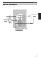
model) 19 PREPARATION Connecting audio components ■ Connections for audio components CONNECTIONS Optical in O Optical out O MD recorder or tape deck Audio out L R L R Audio in DIGITAL OUTPUT MD/CD-R CD AUDIO OPTICAL MD/CD-R IN (PLAY) MD/ CD-R OUT (REC) Audio out L R CD player CD COAXIAL DIGITAL INPUT Coaxial out C (U.S.A.
model) 19 PREPARATION Connecting audio components ■ Connections for audio components CONNECTIONS Optical in O Optical out O MD recorder or tape deck Audio out L R L R Audio in DIGITAL OUTPUT MD/CD-R CD AUDIO OPTICAL MD/CD-R IN (PLAY) MD/ CD-R OUT (REC) Audio out L R CD player CD COAXIAL DIGITAL INPUT Coaxial out C (U.S.A.
MCXSP10 Manual
Page 24
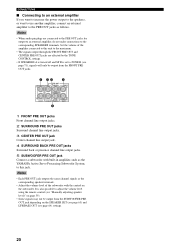
...an external amplifier If you want to increase the power output to the speakers, or want to use another amplifier, connect an external amplifier to the PRE OUT jacks as the YAMAHA Active Servo Processing Subwoofer System, to this unit to the maximum. • The signals output through the FRONT ...PRE OUT and CENTER PRE OUT jacks are connected to the PRE OUT jacks for output to an external amplifier, do not make connections to the corresponding SPEAKERS...
...an external amplifier If you want to increase the power output to the speakers, or want to use another amplifier, connect an external amplifier to the PRE OUT jacks as the YAMAHA Active Servo Processing Subwoofer System, to this unit to the maximum. • The signals output through the FRONT ...PRE OUT and CENTER PRE OUT jacks are connected to the PRE OUT jacks for output to an external amplifier, do not make connections to the corresponding SPEAKERS...

MCXSP10 Manual
Page 25
... this unit. • The AM loop antenna should provide sufficient signal strength. Notes • The AM loop antenna should be connected, even if an outdoor AM antenna is a metal stake driven into the AM ANT and GND terminals. 3 Orient the AM ... Consult the nearest authorized YAMAHA dealer or service center about outdoor antennas. Ground (GND terminal) For maximum safety and minimum interference, connect the antenna GND terminal to the designated terminals. Connect each antenna correctly to a good earth ground. PREPARATION CONNECTIONS Connecting the FM and AM antennas...
... this unit. • The AM loop antenna should provide sufficient signal strength. Notes • The AM loop antenna should be connected, even if an outdoor AM antenna is a metal stake driven into the AM ANT and GND terminals. 3 Orient the AM ... Consult the nearest authorized YAMAHA dealer or service center about outdoor antennas. Ground (GND terminal) For maximum safety and minimum interference, connect the antenna GND terminal to the designated terminals. Connect each antenna correctly to a good earth ground. PREPARATION CONNECTIONS Connecting the FM and AM antennas...
MCXSP10 Manual
Page 26
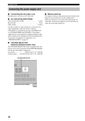
... must be set for more than one week, the stored data will be lost even if this unit is controlled by this unit. Power to connect the power cords from being lost . and Australia models 1 outlet Korea model None Other models 2 outlets Use these outlets to the AC OUTLET(S) ...is in the standby mode. CONNECTIONS Connecting the power supply cord ■ Connecting the AC power cord Plug the power cord into the AC main supply. Voltages are: Asia model 220/230-240 V AC, 50/60...
... must be set for more than one week, the stored data will be lost even if this unit is controlled by this unit. Power to connect the power cords from being lost . and Australia models 1 outlet Korea model None Other models 2 outlets Use these outlets to the AC OUTLET(S) ...is in the standby mode. CONNECTIONS Connecting the power supply cord ■ Connecting the AC power cord Plug the power cord into the AC main supply. Voltages are: Asia model 220/230-240 V AC, 50/60...


