Owner's Manual
Page 4
... voltage BEFORE plugging into the AC main supply. away from the AC power source as long as they may cause fire, damage to set this unit must be set for future reference. 2 Install this unit. - Other components, as it may cause damage and/or discoloration on switches, knobs and/or ...to wide slot and fully insert. This unit is not disconnected from direct sunlight, heat sources, vibration, dust, moisture, and/or cold. Contact qualified YAMAHA service personnel when any reasons. 15 When not planning to use of plug to the wall outlet, even if this unit for any service is...
... voltage BEFORE plugging into the AC main supply. away from the AC power source as long as they may cause fire, damage to set this unit must be set for future reference. 2 Install this unit. - Other components, as it may cause damage and/or discoloration on switches, knobs and/or ...to wide slot and fully insert. This unit is not disconnected from direct sunlight, heat sources, vibration, dust, moisture, and/or cold. Contact qualified YAMAHA service personnel when any reasons. 15 When not planning to use of plug to the wall outlet, even if this unit for any service is...
Owner's Manual
Page 5
... codes from other remote controls (Learn 69 Changing source names in the display window....... 71 Using the Macro feature 72 Clearing function sets 74 Clearing individual functions 75 Controlling each component 77 ZONE 2/ZONE 3 (U.S.A., CANADA, U.K., EUROPE AND AUSTRALIA MODELS ONLY 78 Zone ... display system options menu 82 ADDITIONAL INFORMATION EDITING SOUND FIELD PARAMETERS ......86 What is a sound field 86 Changing parameter settings 86 SOUND FIELD PARAMETER DESCRIPTIONS 87 TROUBLESHOOTING 92 GLOSSARY 97 Audio formats 97 Sound field programs 98 Audio information 99 Video...
... codes from other remote controls (Learn 69 Changing source names in the display window....... 71 Using the Macro feature 72 Clearing function sets 74 Clearing individual functions 75 Controlling each component 77 ZONE 2/ZONE 3 (U.S.A., CANADA, U.K., EUROPE AND AUSTRALIA MODELS ONLY 78 Zone ... display system options menu 82 ADDITIONAL INFORMATION EDITING SOUND FIELD PARAMETERS ......86 What is a sound field 86 Changing parameter settings 86 SOUND FIELD PARAMETER DESCRIPTIONS 87 TROUBLESHOOTING 92 GLOSSARY 97 Audio formats 97 Sound field programs 98 Audio information 99 Video...
Owner's Manual
Page 7
... batteries. • Do not throw away batteries with general house waste; A/B/C/D/E TV MUTE TV INPUT + VOL - If the remote control is cleared, insert new batteries, set up the remote control code and program any acquired functions that you received all of the batteries if you notice conditions such as the operation...
... batteries. • Do not throw away batteries with general house waste; A/B/C/D/E TV MUTE TV INPUT + VOL - If the remote control is cleared, insert new batteries, set up the remote control code and program any acquired functions that you received all of the batteries if you notice conditions such as the operation...
Owner's Manual
Page 8
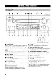
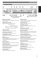
...ON INPUT PURE DIRECT 0 (U.S.A. Note In standby mode, this unit consumes a small amount of all audio channels. When you turn on this unit or sets it to receive infrared-signals from the remote control. 0 VOLUME Controls the output level of power in the memory. This does not affect the REC...("AUTO" indicator on) and manual ("AUTO" indicator off the PURE DIRECT mode. and Europe models only) 1 STANDBY/ON Turns on or off the set of front speakers connected to 7 second delay before this unit. 5 PRESET/TUNING EDIT Switches the function of this unit can reproduce sound. Hold down ...
...ON INPUT PURE DIRECT 0 (U.S.A. Note In standby mode, this unit consumes a small amount of all audio channels. When you turn on this unit or sets it to receive infrared-signals from the remote control. 0 VOLUME Controls the output level of power in the memory. This does not affect the REC...("AUTO" indicator on) and manual ("AUTO" indicator off the PURE DIRECT mode. and Europe models only) 1 STANDBY/ON Turns on or off the set of front speakers connected to 7 second delay before this unit. 5 PRESET/TUNING EDIT Switches the function of this unit can reproduce sound. Hold down ...
Owner's Manual
Page 9
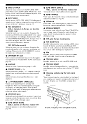
... on the lower part of the panel. When STRAIGHT is connected to E). L TONE CONTROL Use to the standby mode (see page 34). C INPUT MODE Sets the priority (AUTO, DTS, ANALOG) for the front left and right channels. D REC OUT/ZONE 2 (U.S.A., Canada, U.K., Europe and Australia models only)..., the input source is directed to the MULTI CH INPUT jacks. INTRODUCTION B MULTI CH INPUT Selects the source connected to all outputs. When set the unit to connect and input audio signals from their respective speakers without effect processing. ■ U.K. The source in Zone 2 and the...
... on the lower part of the panel. When STRAIGHT is connected to E). L TONE CONTROL Use to the standby mode (see page 34). C INPUT MODE Sets the priority (AUTO, DTS, ANALOG) for the front left and right channels. D REC OUT/ZONE 2 (U.S.A., Canada, U.K., Europe and Australia models only)..., the input source is directed to the MULTI CH INPUT jacks. INTRODUCTION B MULTI CH INPUT Selects the source connected to all outputs. When set the unit to connect and input audio signals from their respective speakers without effect processing. ■ U.K. The source in Zone 2 and the...
Owner's Manual
Page 10
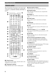
...to program a series of operations for the type of signals received when one component is connected to recall favorite sound field programs, YPAO settings or additional preset stations (see "REMOTE CONTROL FEATURES" on page 66. 1 2 3 POWER TV POWER AV STANDBY SYSTEM POWER A B...CH IN V-AUX CBL/SAT MD/TAPE CD-R E F G H I DTV VCR 1 DVR/VCR2 DVD 4 5 6 7 8 9 0 A B C D SELECT PRESET ++ TV VOL CH -- H SLEEP Sets the sleep timer. 6 SUR 5 6 7 8 1 MEMORY 2 9 0 A SPEAKERS B +10 ENT. Aim this window at the component you can control. 5 PRESET +/- B MEMORY 1/2 Use to two ...
...to program a series of operations for the type of signals received when one component is connected to recall favorite sound field programs, YPAO settings or additional preset stations (see "REMOTE CONTROL FEATURES" on page 66. 1 2 3 POWER TV POWER AV STANDBY SYSTEM POWER A B...CH IN V-AUX CBL/SAT MD/TAPE CD-R E F G H I DTV VCR 1 DVR/VCR2 DVD 4 5 6 7 8 9 0 A B C D SELECT PRESET ++ TV VOL CH -- H SLEEP Sets the sleep timer. 6 SUR 5 6 7 8 1 MEMORY 2 9 0 A SPEAKERS B +10 ENT. Aim this window at the component you can control. 5 PRESET +/- B MEMORY 1/2 Use to two ...
Owner's Manual
Page 11
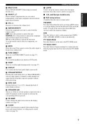
... selector buttons. EON Press this button to this unit. L AMP/SOURCE/TV Selects the component you can control independently of multi-channel software. TV: Set to begin searching for components, see page 71). N PURE DIRECT Turns on or off or on. SUR Switches between the PS mode, PTY mode,...display menu mode. R STRAIGHT/EFFECT Switches the sound fields off PURE DIRECT mode (see page 69). ■ U.K. CONTROLS AND FUNCTIONS W LEARN Used to set the remote control codes for a station after the desired program type has been selected in tuner mode) FREQ/RDS Press this button to...
... selector buttons. EON Press this button to this unit. L AMP/SOURCE/TV Selects the component you can control independently of multi-channel software. TV: Set to begin searching for components, see page 71). N PURE DIRECT Turns on or off or on. SUR Switches between the PS mode, PTY mode,...display menu mode. R STRAIGHT/EFFECT Switches the sound fields off PURE DIRECT mode (see page 69). ■ U.K. CONTROLS AND FUNCTIONS W LEARN Used to set the remote control codes for a station after the desired program type has been selected in tuner mode) FREQ/RDS Press this button to...
Owner's Manual
Page 13
...up when you select a CINEMA DSP sound field program. 6 YPAO indicator Lights up during the auto setup procedure and when the auto setup speaker settings are selected, or when bi-wiring. B SLEEP indicator Lights up while the sleep timer is on . K MUTE indicator Blinks while the MUTE function... is on . 9 Both indicators light up when both sets of this unit is receiving a stereo signal for an FM stereo broadcast while the AUTO indicator is lit. 9 VOLUME level indicator Indicates the volume level...
...up when you select a CINEMA DSP sound field program. 6 YPAO indicator Lights up during the auto setup procedure and when the auto setup speaker settings are selected, or when bi-wiring. B SLEEP indicator Lights up while the sleep timer is on . K MUTE indicator Blinks while the MUTE function... is on . 9 Both indicators light up when both sets of this unit is receiving a stereo signal for an FM stereo broadcast while the AUTO indicator is lit. 9 VOLUME level indicator Indicates the volume level...
Owner's Manual
Page 14
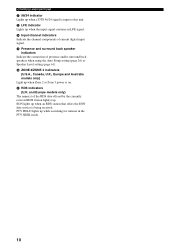
N Input channel indicators Indicate the channel components of presence and/or surround back speakers when using the Auto Setup setting (page 26) or Speaker Level setting (page 61). P ZONE 2/ZONE 3 indicators (U.S.A., Canada, U.K., Europe and Australia models only) Light up while searching for stations in the PTY SEEK mode. 10 PTY HOLD ...
N Input channel indicators Indicate the channel components of presence and/or surround back speakers when using the Auto Setup setting (page 26) or Speaker Level setting (page 61). P ZONE 2/ZONE 3 indicators (U.S.A., Canada, U.K., Europe and Australia models only) Light up while searching for stations in the PTY SEEK mode. 10 PTY HOLD ...
Owner's Manual
Page 16
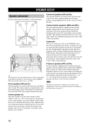
... speaker centrally between the front speakers and as close to use it is not practical to the monitor as possible, such as the YAMAHA Active Servo Processing Subwoofer System, is better to -back transitions. Surround back speakers (SBR and SBL) The surround back speakers supplement ... at the front of the LFE (lowfrequency effect) channel included in ) . 1.8 m (6 ft) 1.8 m (6 ft) y The illustrations show the standard speaker setting recommended by CINEMA DSP (see page 99). The distance of each speaker from the ideal listening position. PL PR C FL FR 30˚ SL 60...
... speaker centrally between the front speakers and as close to use it is not practical to the monitor as possible, such as the YAMAHA Active Servo Processing Subwoofer System, is better to -back transitions. Surround back speakers (SBR and SBL) The surround back speakers supplement ... at the front of the LFE (lowfrequency effect) channel included in ) . 1.8 m (6 ft) 1.8 m (6 ft) y The illustrations show the standard speaker setting recommended by CINEMA DSP (see page 99). The distance of each speaker from the ideal listening position. PL PR C FL FR 30˚ SL 60...
Owner's Manual
Page 17
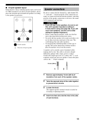
... unit and your speaker. If the connections are faulty, no sound will use this unit's initial setting for speaker impedance. • Before connecting the speakers, make sure that this unit. FL C FR SL SR 30˚ 30˚ SBL ... this unit and/or speakers. • Use magnetically shielded speakers. Connect the striped (grooved, etc.) cable to the "+" (red) terminals on this unit's speaker impedance setting to connect the left channel (L), right channel (R), "+" (red) and "-" (black) properly. Connect the plain cable to the "-" (black) terminals. 10 mm (3/8 in) 1 2 1...
... unit and your speaker. If the connections are faulty, no sound will use this unit's initial setting for speaker impedance. • Before connecting the speakers, make sure that this unit. FL C FR SL SR 30˚ 30˚ SBL ... this unit and/or speakers. • Use magnetically shielded speakers. Connect the striped (grooved, etc.) cable to the "+" (red) terminals on this unit's speaker impedance setting to connect the left channel (L), right channel (R), "+" (red) and "-" (black) properly. Connect the plain cable to the "-" (black) terminals. 10 mm (3/8 in) 1 2 1...
Owner's Manual
Page 19
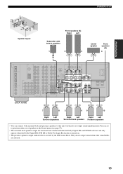
... to this unit, but they do not output sound when other sound fields are selected. 15 They do not output sound simultaneously.You can set to prioritize either set of speakers in the Sound menu (see page 57). • The surround back speakers output the surround back channel included in amplifier 1 2 3 Center...
... to this unit, but they do not output sound when other sound fields are selected. 15 They do not output sound simultaneously.You can set to prioritize either set of speakers in the Sound menu (see page 57). • The surround back speakers output the surround back channel included in amplifier 1 2 3 Center...
Owner's Manual
Page 21
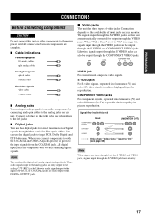
... the digital jacks to input PCM, Dolby Digital and DTS bitstreams. When you connect components to both the COAXIAL and OPTICAL jacks, priority is set to "On" (see page 62), signals input through the VIDEO jacks can also be output through either coaxial or fiber optic cables. You ...can input analog signals from the COAXIAL jack. is set to "On" (see page 62) Note When signals are automatically converted for direct transmission of digital signals through the S VIDEO and COMPONENT ...
... the digital jacks to input PCM, Dolby Digital and DTS bitstreams. When you connect components to both the COAXIAL and OPTICAL jacks, priority is set to "On" (see page 62), signals input through the VIDEO jacks can also be output through either coaxial or fiber optic cables. You ...can input analog signals from the COAXIAL jack. is set to "On" (see page 62) Note When signals are automatically converted for direct transmission of digital signals through the S VIDEO and COMPONENT ...
Owner's Manual
Page 23
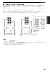
... Assign: Front Input (page 54) together with 6 additional input jacks (left and right FRONT, CENTER, left and right input jacks for missing speakers. If you set Multi CH Assign: Input Channels to 8ch (see page 54), you cannot select sound field programs. • This unit does not redirect signals input to...
... Assign: Front Input (page 54) together with 6 additional input jacks (left and right FRONT, CENTER, left and right input jacks for missing speakers. If you set Multi CH Assign: Input Channels to 8ch (see page 54), you cannot select sound field programs. • This unit does not redirect signals input to...
Owner's Manual
Page 26
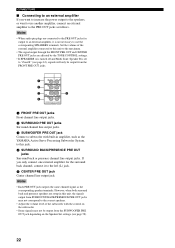
...Some signals may not be output from the SUBWOOFER PRE OUT jack depending on the Speaker Set settings (see page 58). 22 Notes • Each PRE OUT jack outputs the same channel signal as the YAMAHA Active Servo Processing Subwoofer System, to the left (L) jack. 5 CENTER PRE OUT jack ... SPEAKERS terminals. However, when both surround back and presence speakers are connected to the PRE OUT jacks for the surround back channel, connect it is set to "Zone B" (see page 63), signals will only be output from the FRONT PRE OUT jacks. 1 2 3 4 R L FRONT R L SURROUND SUB WOOFER R ...
...Some signals may not be output from the SUBWOOFER PRE OUT jack depending on the Speaker Set settings (see page 58). 22 Notes • Each PRE OUT jack outputs the same channel signal as the YAMAHA Active Servo Processing Subwoofer System, to the left (L) jack. 5 CENTER PRE OUT jack ... SPEAKERS terminals. However, when both surround back and presence speakers are connected to the PRE OUT jacks for the surround back channel, connect it is set to "Zone B" (see page 63), signals will only be output from the FRONT PRE OUT jacks. 1 2 3 4 R L FRONT R L SURROUND SUB WOOFER R ...
Owner's Manual
Page 27
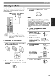
... and clamp it to the terminals on this unit. • A property installed outdoor antenna provides clearer reception than an indoor one. Consult the nearest authorized YAMAHA dealer or service center about outdoor antennas. ■ 75-ohm/300-ohm antenna adapter (U.K. Unit: mm (in) 3 Cut the lead wire and remove ... should always be connected, even if an outdoor AM antenna is a metal stake driven into moist earth. ■ Connecting the AM loop antenna 1 Set up the AM loop antenna, then connect it with this unit. model only) 1 Open the cover of the included 75-ohm/300-ohm antenna adapter...
... and clamp it to the terminals on this unit. • A property installed outdoor antenna provides clearer reception than an indoor one. Consult the nearest authorized YAMAHA dealer or service center about outdoor antennas. ■ 75-ohm/300-ohm antenna adapter (U.K. Unit: mm (in) 3 Cut the lead wire and remove ... should always be connected, even if an outdoor AM antenna is a metal stake driven into moist earth. ■ Connecting the AM loop antenna 1 Set up the AM loop antenna, then connect it with this unit. model only) 1 Open the cover of the included 75-ohm/300-ohm antenna adapter...
Owner's Manual
Page 28
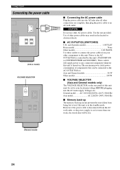
... after all other components to this unit's STANDBY/ON (or SYSTEM POWER and STANDBY). CONNECTIONS Connecting the power cable AC OUTLETS (U.S.A. These outlets will be set for more than one provided. Power to an AC wall outlet. Voltages are complete, then plug the power cable to the AC OUTLETS(S) is : Asia...
... after all other components to this unit's STANDBY/ON (or SYSTEM POWER and STANDBY). CONNECTIONS Connecting the power cable AC OUTLETS (U.S.A. These outlets will be set for more than one provided. Power to an AC wall outlet. Voltages are complete, then plug the power cable to the AC OUTLETS(S) is : Asia...
Owner's Manual
Page 29
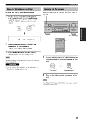
...the power. (U.S.A. CAUTION If you are complete, turn on the video monitor connected to select the impedance of your speakers. PREPARATION Speaker impedance setting Be sure this unit is located in the standby mode. 1 On the front panel, while holding down STRAIGHT/EFFECT, press STANDBY/ON. ...1 ++ SELECT AMP + 1 Press STANDBY/ON (SYSTEM POWER on the remote controls) to turn on the remote control) to exit the setting. Note Speaker impedance setting function is in the Advanced menu (see page 81). SYSTEM POWER STANDBY /ON or Front panel Remote control 2 Turn on the power of...
...the power. (U.S.A. CAUTION If you are complete, turn on the video monitor connected to select the impedance of your speakers. PREPARATION Speaker impedance setting Be sure this unit is located in the standby mode. 1 On the front panel, while holding down STRAIGHT/EFFECT, press STANDBY/ON. ...1 ++ SELECT AMP + 1 Press STANDBY/ON (SYSTEM POWER on the remote controls) to turn on the remote control) to exit the setting. Note Speaker impedance setting function is in the Advanced menu (see page 81). SYSTEM POWER STANDBY /ON or Front panel Remote control 2 Turn on the power of...

Owner's Manual
Page 30
... of each speaker. Notes • Please be advised that it on the front panel. Size Checks the speaker's frequency response and sets the appropriate low frequency crossover for each speaker. SOURCE /REMOTE DVD MD/TAPE D-TV CD-R A/B/C/D/E CBL/SAT TUNER VCR 1 CD...direct sunlight. - Level Checks and adjusts the sound level (volume) of each channel. AUTO SETUP AUTO SETUP Introduction This receiver employs YAMAHA Parametric Room Acoustic Optimizer (YPAO) technology which speakers are seated in your actual listening environment. Wiring Checks which lets you use a...
... of each speaker. Notes • Please be advised that it on the front panel. Size Checks the speaker's frequency response and sets the appropriate low frequency crossover for each speaker. SOURCE /REMOTE DVD MD/TAPE D-TV CD-R A/B/C/D/E CBL/SAT TUNER VCR 1 CD...direct sunlight. - Level Checks and adjusts the sound level (volume) of each channel. AUTO SETUP AUTO SETUP Introduction This receiver employs YAMAHA Parametric Room Acoustic Optimizer (YPAO) technology which speakers are seated in your actual listening environment. Wiring Checks which lets you use a...
Owner's Manual
Page 31
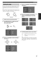
...possible during the auto setup procedure (YPAO). y If your subwoofer can adjust the output volume and the crossover frequency, set the volume to about half way (or slightly less) and set the crossover frequency to select Setup Menu, then press h. If there is too much ambient noise, the results may ...Menu Setup Type Start 27 PREPARATION AUTO SETUP Starting the setup For best results, make sure that "Small" or "Small x2" is selected in Speaker Set (page 58) and that "80Hz (THX)" is selected in Bass Cross Over (page 60). AMP SOURCE TV TOP TITLE Wiring Distance Size Wiring ...
...possible during the auto setup procedure (YPAO). y If your subwoofer can adjust the output volume and the crossover frequency, set the volume to about half way (or slightly less) and set the crossover frequency to select Setup Menu, then press h. If there is too much ambient noise, the results may ...Menu Setup Type Start 27 PREPARATION AUTO SETUP Starting the setup For best results, make sure that "Small" or "Small x2" is selected in Speaker Set (page 58) and that "80Hz (THX)" is selected in Bass Cross Over (page 60). AMP SOURCE TV TOP TITLE Wiring Distance Size Wiring ...


