
Owner's Manual
Page 4
... unit, which may get exposed to hot, and do not locate this unit with a newspaper, tablecloth, curtain, etc. Buring objects (i.e. YAMAHA will not be used. FREQUENCY STEP switch (China and general models only) Because the interstation frequency spacing differs in your local main voltage BEFORE...in a environment with at the back of ventilation space on this unit - To prevent fire or electrical shock, do not place: - Other components, as they may cause damage and/or discoloration on the rear of liquid. 4 Do not expose this unit to sudden temperature changes from the...
... unit, which may get exposed to hot, and do not locate this unit with a newspaper, tablecloth, curtain, etc. Buring objects (i.e. YAMAHA will not be used. FREQUENCY STEP switch (China and general models only) Because the interstation frequency spacing differs in your local main voltage BEFORE...in a environment with at the back of ventilation space on this unit - To prevent fire or electrical shock, do not place: - Other components, as they may cause damage and/or discoloration on the rear of liquid. 4 Do not expose this unit to sudden temperature changes from the...
Owner's Manual
Page 5
...Rear Panel 10 PREPARATION SPEAKER SETUP 11 Speakers to Be Used 11 Speaker Placement 11 CONNECTIONS 12 Before Connecting Components 12 Connecting Audio Components 12 Connecting Video Components 14 Connecting the Speakers 16 Connecting to an External Amplifier 18 Connecting an External Decoder 18 IMPEDANCE SELECTOR ... SLEEP TIMER 46 Setting the Sleep Timer 46 Canceling the Sleep Timer 46 REMOTE CONTROL FEATURES 47 Control Area 47 Each Component Control Area 49 Setting the Manufacturer Code 54 Programming a New Remote Control Function (Learn Feature 55 Using the Macro Feature...
...Rear Panel 10 PREPARATION SPEAKER SETUP 11 Speakers to Be Used 11 Speaker Placement 11 CONNECTIONS 12 Before Connecting Components 12 Connecting Audio Components 12 Connecting Video Components 14 Connecting the Speakers 16 Connecting to an External Amplifier 18 Connecting an External Decoder 18 IMPEDANCE SELECTOR ... SLEEP TIMER 46 Setting the Sleep Timer 46 Canceling the Sleep Timer 46 REMOTE CONTROL FEATURES 47 Control Area 47 Each Component Control Area 49 Setting the Manufacturer Code 54 Programming a New Remote Control Function (Learn Feature 55 Using the Macro Feature...
Owner's Manual
Page 6
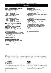
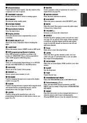
...BASS EXTENSION Button for Reinforcing Bass Response x On Screen Display Function Helpful in Controlling This Unit x S Video Signal Input/Output Capability x Component Video Input/Output Capability x Optical and Coaxial Digital Audio Signal Jacks x Sleep Timer x Multi-Function Remote Control x Custom Installation Facility ... performed by using either the buttons on the main unit or on the remote control is given in parentheses in this YAMAHA AV receiver. All rights reserved. 2 Manufactured under license from Digital Theater Systems, Inc. Manufactured under license from Dolby ...
...BASS EXTENSION Button for Reinforcing Bass Response x On Screen Display Function Helpful in Controlling This Unit x S Video Signal Input/Output Capability x Component Video Input/Output Capability x Optical and Coaxial Digital Audio Signal Jacks x Sleep Timer x Multi-Function Remote Control x Custom Installation Facility ... performed by using either the buttons on the main unit or on the remote control is given in parentheses in this YAMAHA AV receiver. All rights reserved. 2 Manufactured under license from Digital Theater Systems, Inc. Manufactured under license from Dolby ...
Owner's Manual
Page 10
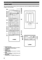
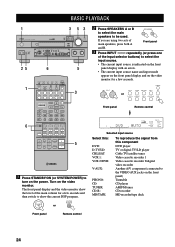
... the manufacturer code. A/B/C/D/E PRESET + TV INPUT CH TV MUTE - D Others Functions vary depending on pages 47 to conveniently operates your components that are set up with the remote control. DISC MUTE EFFECT + VOLUME - B A and B buttons See page 47. C Operation... section Provides functions such as play, stop, skip, etc. See "REMOTE CONTROL FEATURES" on your other components. CHAPTER + POWER REC / STOP PAUSE PLAY 10KEY DSP HALL 1 HALL 2 CHURCH JAZZ CLUB 1 2 3 4 ROCK CONCERT 5 STADIUM 6 ENTERTAINMENT 7 TV SPORTS...
... the manufacturer code. A/B/C/D/E PRESET + TV INPUT CH TV MUTE - D Others Functions vary depending on pages 47 to conveniently operates your components that are set up with the remote control. DISC MUTE EFFECT + VOLUME - B A and B buttons See page 47. C Operation... section Provides functions such as play, stop, skip, etc. See "REMOTE CONTROL FEATURES" on your other components. CHAPTER + POWER REC / STOP PAUSE PLAY 10KEY DSP HALL 1 HALL 2 CHURCH JAZZ CLUB 1 2 3 4 ROCK CONCERT 5 STADIUM 6 ENTERTAINMENT 7 TV SPORTS...
Owner's Manual
Page 11
...17)) on the power of this unit. 5 Input selector buttons Select the input source. 6 Display window Shows the selected source component that you have changed the batteries or when the remote control stops working properly. (Pressing RESET does not clear the acquired functions.) ... Infrared window Outputs infrared control signals. q A/B/C/D/E Selects one of operations for the LFE channel are controlling. 7 SOURCE SELECT k/n Selects the source component without switching the input. 8 10KEY/DSP Selects the numeric button (10KEY) mode or DSP mode. 9 DSP program group/Numeric buttons Select DSP ...
...17)) on the power of this unit. 5 Input selector buttons Select the input source. 6 Display window Shows the selected source component that you have changed the batteries or when the remote control stops working properly. (Pressing RESET does not clear the acquired functions.) ... Infrared window Outputs infrared control signals. q A/B/C/D/E Selects one of operations for the LFE channel are controlling. 7 SOURCE SELECT k/n Selects the source component without switching the input. 8 10KEY/DSP Selects the numeric button (10KEY) mode or DSP mode. 9 DSP program group/Numeric buttons Select DSP ...
Owner's Manual
Page 14
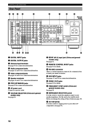
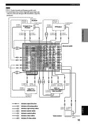
... jacks See page 61 for details. r ZONE 2 OUT jacks See page 61 for details. u AC OUTLET(S) Use these outlets to supply power to your other A/V components (see page 19). CD 232C PHONO MAIN AUDIO R L S VIDEO DVD D-TV /LD CBL /SAT IN VCR 1 OUT IN VCR 2 /DVR OUT CBL /SAT SURROUND ZONE... IN OUT REMOTE CONTROL SUB CENTER WOOFER 6CH INPUT 100 kHz/10 kHz 50 kHz/ 9 kHz FM AM FREQUENCY STEP MONITOR OUT S VIDEO VIDEO VIDEO COMPONENT DVD Y PB/ CB PR/ CR D-TV/LD Y PB/ CB PR/ CR MONITOR OUT Y PB/ CB PR/ CR VIDEO + R A MAIN B CENTER + R + REAR (SURROUND) - Consult your speaker...
... jacks See page 61 for details. r ZONE 2 OUT jacks See page 61 for details. u AC OUTLET(S) Use these outlets to supply power to your other A/V components (see page 19). CD 232C PHONO MAIN AUDIO R L S VIDEO DVD D-TV /LD CBL /SAT IN VCR 1 OUT IN VCR 2 /DVR OUT CBL /SAT SURROUND ZONE... IN OUT REMOTE CONTROL SUB CENTER WOOFER 6CH INPUT 100 kHz/10 kHz 50 kHz/ 9 kHz FM AM FREQUENCY STEP MONITOR OUT S VIDEO VIDEO VIDEO COMPONENT DVD Y PB/ CB PR/ CR D-TV/LD Y PB/ CB PR/ CR MONITOR OUT Y PB/ CB PR/ CR VIDEO + R A MAIN B CENTER + R + REAR (SURROUND) - Consult your speaker...
Owner's Manual
Page 16
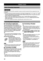
... reduces noise in the standby mode, the recorded sound may not function properly. YAMAHA applies this labeling system to all its power on this unit conform to the input signals from other YAMAHA audio components (such as a tape deck, MD recorder and CD player or changer), connect...this unit is given to the EIA standard. When you have different jack names. s Connecting a turntable PHONO jacks are correct. Some components require different connection methods and have completed all connections are made correctly, that does not conform to this unit while this unit. •...
... reduces noise in the standby mode, the recorded sound may not function properly. YAMAHA applies this labeling system to all its power on this unit conform to the input signals from other YAMAHA audio components (such as a tape deck, MD recorder and CD player or changer), connect...this unit is given to the EIA standard. When you have different jack names. s Connecting a turntable PHONO jacks are correct. Some components require different connection methods and have completed all connections are made correctly, that does not conform to this unit while this unit. •...

Owner's Manual
Page 17
... OUTPUT L R C COAXIAL OUTPUT DIGITAL OUTPUT MD/ TAPE TUNER AM CD-R ANT OPTICAL GND AUDIO R L IN (PLAY) MD/TAPE OUT (REC) AUDIO R L S VIDEO DVD VIDEO VIDEO COMPONENT DVD Y D-TV PB/ /LD CB CD IN (PLAY) CBL PR/ /SAT CR CD-R 75 UNBAL. ADVANCED OPERATION ADDITIONAL INFORMATION APPENDIX English 13 CD 232C PHONO...
... OUTPUT L R C COAXIAL OUTPUT DIGITAL OUTPUT MD/ TAPE TUNER AM CD-R ANT OPTICAL GND AUDIO R L IN (PLAY) MD/TAPE OUT (REC) AUDIO R L S VIDEO DVD VIDEO VIDEO COMPONENT DVD Y D-TV PB/ /LD CB CD IN (PLAY) CBL PR/ /SAT CR CD-R 75 UNBAL. ADVANCED OPERATION ADDITIONAL INFORMATION APPENDIX English 13 CD 232C PHONO...
Owner's Manual
Page 18
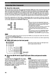
...AUX S V L R O These jacks are separated into luminance (Y) and color (C) video signals. s VIDEO AUX jacks (on this unit. The description of the component video jacks may be output by using "7 I/O ASSIGNMENT" on the SET MENU (see page 26). Connect the S-video signal output jack on your LD player... Dolby Digital RF (AC-3) signal output jack, connect it to make S-video connections to this unit. You must playback an LD encoded with the component being connected. OPTICAL OUT AUDIO OUT R AUDIO OUT L VIDEO OUT S VIDEO OUT Game console s About the q RF (AC-3) signal input ...
...AUX S V L R O These jacks are separated into luminance (Y) and color (C) video signals. s VIDEO AUX jacks (on this unit. The description of the component video jacks may be output by using "7 I/O ASSIGNMENT" on the SET MENU (see page 26). Connect the S-video signal output jack on your LD player... Dolby Digital RF (AC-3) signal output jack, connect it to make S-video connections to this unit. You must playback an LD encoded with the component being connected. OPTICAL OUT AUDIO OUT R AUDIO OUT L VIDEO OUT S VIDEO OUT Game console s About the q RF (AC-3) signal input ...
Owner's Manual
Page 19
...CB D-TV /LD O PHONO OPTICAL COAXIAL RS- RF OUTPUT OPTICAL LD player OUTPUT COMPONENT AUDIO OUTPUT OUTPUT TV/digital TV or LD player CONNECTIONS OPTICAL OUTPUT AUDIO OUTPUT DVD player COMPONENT OUTPUT S VIDEO OUTPUT S VIDEO V OUTPUT LR S VIDEO OUTPUT S VIDEO V ...OUTPUT PREPARATION BASIC OPERATION ADVANCED OPERATION ADDITIONAL INFORMATION DIGITAL OUTPUT MD/ TAPE TUNER AUDIO R L AUDIO R L S VIDEO VIDEO VIDEO COMPONENT DVD (General model) L IN (PLAY) DVD Y AM MD/TAPE R CD-R ANT OUT (REC) D-TV PB/ /LD CB OPTICAL GND CD IN...
...CB D-TV /LD O PHONO OPTICAL COAXIAL RS- RF OUTPUT OPTICAL LD player OUTPUT COMPONENT AUDIO OUTPUT OUTPUT TV/digital TV or LD player CONNECTIONS OPTICAL OUTPUT AUDIO OUTPUT DVD player COMPONENT OUTPUT S VIDEO OUTPUT S VIDEO V OUTPUT LR S VIDEO OUTPUT S VIDEO V ...OUTPUT PREPARATION BASIC OPERATION ADVANCED OPERATION ADDITIONAL INFORMATION DIGITAL OUTPUT MD/ TAPE TUNER AUDIO R L AUDIO R L S VIDEO VIDEO VIDEO COMPONENT DVD (General model) L IN (PLAY) DVD Y AM MD/TAPE R CD-R ANT OUT (REC) D-TV PB/ /LD CB OPTICAL GND CD IN...
Owner's Manual
Page 23
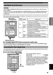
... STANDBY/ON (or SYSTEM POWER) is pressed, the IMPEDANCE SELECTOR switch may be 8 Ω or higher. The maximum power (total power consumption of components) that can be fully slid to the AC OUTLET(S) is controlled by this unit's STANDBY/ON (or SYSTEM POWER and STANDBY). If this unit fails...Power Supply Cords After completing all connections, connect the AC power cord to move this switch only when this unit is in your components to any connected component whenever this unit is turned on , otherwise the unit may not be connected to the impedance of the speakers in the standby ...
... STANDBY/ON (or SYSTEM POWER) is pressed, the IMPEDANCE SELECTOR switch may be 8 Ω or higher. The maximum power (total power consumption of components) that can be fully slid to the AC OUTLET(S) is controlled by this unit's STANDBY/ON (or SYSTEM POWER and STANDBY). If this unit fails...Power Supply Cords After completing all connections, connect the AC power cord to move this switch only when this unit is in your components to any connected component whenever this unit is turned on , otherwise the unit may not be connected to the impedance of the speakers in the standby ...
Owner's Manual
Page 24
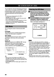
... to both the S VIDEO IN and composite VIDEO IN jacks, and both the S-video and composite video signals. • If your video monitor to the COMPONENT VIDEO jacks and either VIDEO or S VIDEO jacks if you choose the full display mode, INPUT l / h, VOLUME and some other types of the main volume... front panel display. • The SET MENU and test tone display appear regardless of noise may produce unstable images. 20 If no changes to the COMPONENT VIDEO jacks of this information on the remote control repeatedly to the REC OUT jack, and will not be recorded with a lot of the OSD...
... to both the S VIDEO IN and composite VIDEO IN jacks, and both the S-video and composite video signals. • If your video monitor to the COMPONENT VIDEO jacks and either VIDEO or S VIDEO jacks if you choose the full display mode, INPUT l / h, VOLUME and some other types of the main volume... front panel display. • The SET MENU and test tone display appear regardless of noise may produce unstable images. 20 If no changes to the COMPONENT VIDEO jacks of this information on the remote control repeatedly to the REC OUT jack, and will not be recorded with a lot of the OSD...
Owner's Manual
Page 28
... source Select this: DVD: D-TV/LD: CBL/SAT: VCR 1: VCR 2/DVR: V-AUX: PHONO: CD: TUNER: CD-R: MD/TAPE: To reproduce the signal from this component DVD player TV or digital TV/LD player Cable TV/satellite tuner Video cassette recorder 1 Video cassette recorder 2/digital video recorder Another... A/V component (connected to turn on the front panel) Turntable CD player AM/FM tuner CD recorder MD recorder/tape deck Front panel Remote control 24 DISC ...
... source Select this: DVD: D-TV/LD: CBL/SAT: VCR 1: VCR 2/DVR: V-AUX: PHONO: CD: TUNER: CD-R: MD/TAPE: To reproduce the signal from this component DVD player TV or digital TV/LD player Cable TV/satellite tuner Video cassette recorder 1 Video cassette recorder 2/digital video recorder Another... A/V component (connected to turn on the front panel) Turntable CD player AM/FM tuner CD recorder MD recorder/tape deck Front panel Remote control 24 DISC ...
Owner's Manual
Page 29
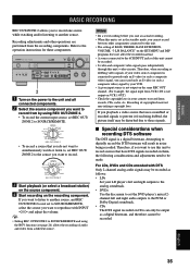
...CD PHONO 2. ADVANCED OPERATION ADDITIONAL INFORMATION APPENDIX English 25 BASIC PLAYBACK 6 Use the digital sound field processor. Refer to the operation instructions for the component. 5 Adjust the volume to set to the previous volume level, press MUTE again. Note • If "1B MAIN SP" on the SET ... source connected to the 6CH INPUT jacks together with INPUT l / h (or the input selector buttons), press 6CH INPUT to turn on the component. y • You can also cancel mute to the 6CH INPUT jacks Press 6CH INPUT until "6CH INPUT" appears on the front panel display...
...CD PHONO 2. ADVANCED OPERATION ADDITIONAL INFORMATION APPENDIX English 25 BASIC PLAYBACK 6 Use the digital sound field processor. Refer to the operation instructions for the component. 5 Adjust the volume to set to the previous volume level, press MUTE again. Note • If "1B MAIN SP" on the SET ... source connected to the 6CH INPUT jacks together with INPUT l / h (or the input selector buttons), press 6CH INPUT to turn on the component. y • You can also cancel mute to the 6CH INPUT jacks Press 6CH INPUT until "6CH INPUT" appears on the front panel display...
Owner's Manual
Page 30
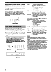
... unit, the input mode is selected, this mode, only the digital input signal encoded with the input selector buttons on the video monitor. If your component is connected to select the input source on the remote control) repeatedly until the desired input mode is shown on the front panel display and...
... unit, the input mode is selected, this mode, only the digital input signal encoded with the input selector buttons on the video monitor. If your component is connected to select the input source on the remote control) repeatedly until the desired input mode is shown on the front panel display and...
Owner's Manual
Page 31
..." mode to prevent noise from the pause or chapter forwarding function to normal playback, you may not be able to PCM or analog. • Some A/V components such as necessary. • While you are operating the LD player and playing a disc encoded with a Dolby Digital signal, if you play a source encoded with...
..." mode to prevent noise from the pause or chapter forwarding function to normal playback, you may not be able to PCM or analog. • Some A/V components such as necessary. • While you are operating the LD player and playing a disc encoded with a Dolby Digital signal, if you play a source encoded with...
Owner's Manual
Page 39
...LD CD-R CBL/SAT VCR 1 TUNER CD VCR2 /DVR V-AUX PHONO REC OUT/ZONE 2 3 Start playback (or select a broadcast station) on the source component. 4 Start recording on VCR 1 OUT.) • Check the copyright laws in noise being dubbed, the picture itself may be recorded. • S-video and ...that uses scrambled or encoded signals to prevent it from being recorded. Refer to digitally record the DTS bitstream will result in your video source component is connected to provide only an S-video (or only a composite video) signal, you want to simultaneously watch or listen to, set REC...
...LD CD-R CBL/SAT VCR 1 TUNER CD VCR2 /DVR V-AUX PHONO REC OUT/ZONE 2 3 Start playback (or select a broadcast station) on the source component. 4 Start recording on VCR 1 OUT.) • Check the copyright laws in noise being dubbed, the picture itself may be recorded. • S-video and ...that uses scrambled or encoded signals to prevent it from being recorded. Refer to digitally record the DTS bitstream will result in your video source component is connected to provide only an S-video (or only a composite video) signal, you want to simultaneously watch or listen to, set REC...

Owner's Manual
Page 45
...to 9, a space, a to z, a space, #, *, +, and so on the video monitor, and the test tone starts alternating among the speakers. s 7A [A] [B] (for the COMPONENT VIDEO jacks) Initial settings: [A] DVD [B] D-TV/LD s 7B (1) (2) (for both BASS and TRBL (treble) 5 CENTER GEQ (center graphic equalizer) Use this feature to go in...2 Press -/+ to adjust the level of the output level from INPUT RENAME. 7 I/O ASSIGNMENT Use this feature to designate the input for the COMPONENT jacks (A and B) and the DIGITAL INPUT/OUTPUT jacks (1 to 8 (or 9 for the China and general models only)) to decrease the ...
...to 9, a space, a to z, a space, #, *, +, and so on the video monitor, and the test tone starts alternating among the speakers. s 7A [A] [B] (for the COMPONENT VIDEO jacks) Initial settings: [A] DVD [B] D-TV/LD s 7B (1) (2) (for both BASS and TRBL (treble) 5 CENTER GEQ (center graphic equalizer) Use this feature to go in...2 Press -/+ to adjust the level of the output level from INPUT RENAME. 7 I/O ASSIGNMENT Use this feature to designate the input for the COMPONENT jacks (A and B) and the DIGITAL INPUT/OUTPUT jacks (1 to 8 (or 9 for the China and general models only)) to decrease the ...
Owner's Manual
Page 48
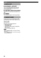
... SHIFT (OSD off-set position) This setting is used to blue if the video source is not being reproduced (or the power of the source component is set to DSP program parameter values and other SET MENU items. 44
... SHIFT (OSD off-set position) This setting is used to blue if the video source is not being reproduced (or the power of the source component is set to DSP program parameter values and other SET MENU items. 44
Owner's Manual
Page 50
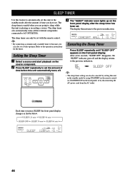
... Timer 1 Select a source and start playback on the front panel) or by using STANDBY on the remote control (or STANDBY/ON on the source component. 2 Press SLEEP repeatedly to set the amount of time you press SLEEP, the front panel display changes as shown below. After a few seconds, ..."SLEEP OFF" disappears, the "SLEEP" indicator goes off the external components connected to AC OUTLET(S). SLEEP TIMER Use this feature to automatically set this unit in the standby mode by disconnecting the AC power cord from...
... Timer 1 Select a source and start playback on the front panel) or by using STANDBY on the remote control (or STANDBY/ON on the source component. 2 Press SLEEP repeatedly to set the amount of time you press SLEEP, the front panel display changes as shown below. After a few seconds, ..."SLEEP OFF" disappears, the "SLEEP" indicator goes off the external components connected to AC OUTLET(S). SLEEP TIMER Use this feature to automatically set this unit in the standby mode by disconnecting the AC power cord from...


