Owners Manual
Page 4
.... MODEL: Serial No.: The serial number is faulty. 18 Before moving this unit, press STANDBY/ON to set to the standby mode. We Want You Listening For A Lifetime YAMAHA and the Electronic Industries Association's Consumer Electronics Group want you to avoid prolonged exposure from cold to get the ...unit in a safe place for future reference. 2 Install this unit for future reference. Using this unit with Canadian ICES-003. Contact qualified YAMAHA service personnel when any damage resulting from use force on the rear panel of plug to consume a very small quantity of this unit. This...
.... MODEL: Serial No.: The serial number is faulty. 18 Before moving this unit, press STANDBY/ON to set to the standby mode. We Want You Listening For A Lifetime YAMAHA and the Electronic Industries Association's Consumer Electronics Group want you to avoid prolonged exposure from cold to get the ...unit in a safe place for future reference. 2 Install this unit for future reference. Using this unit with Canadian ICES-003. Contact qualified YAMAHA service personnel when any damage resulting from use force on the rear panel of plug to consume a very small quantity of this unit. This...
Owners Manual
Page 5
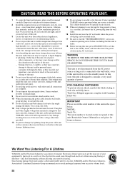
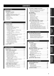
... a DVD player, a DVD recorder, a VCR or an STB 19 Connecting a CD player, an MD player or a tape deck 21 Connecting a YAMAHA iPod universal dock ........ 22 Connecting a multi-format player or an external decoder 23 Connecting a game console, a video camera or a portable audio player ... functions 53 Activating XM Satellite Radio 54 Basic XM Satellite Radio operations 55 Selecting the XM Satellite Radio search mode ....... 56 Setting the XM Satellite Radio preset channels ...... 60 Displaying the XM Satellite Radio information...... 61 SOUND FIELD PROGRAMS SOUND FIELD PROGRAMS 63...
... a DVD player, a DVD recorder, a VCR or an STB 19 Connecting a CD player, an MD player or a tape deck 21 Connecting a YAMAHA iPod universal dock ........ 22 Connecting a multi-format player or an external decoder 23 Connecting a game console, a video camera or a portable audio player ... functions 53 Activating XM Satellite Radio 54 Basic XM Satellite Radio operations 55 Selecting the XM Satellite Radio search mode ....... 56 Setting the XM Satellite Radio preset channels ...... 60 Displaying the XM Satellite Radio information...... 61 SOUND FIELD PROGRAMS SOUND FIELD PROGRAMS 63...

Owners Manual
Page 7
... STARTED GETTING STARTED Supplied accessories Check that may have the same shape and color. • If the batteries have been cleared. 3 EFFECT SET MENU MENU SRCH MODE A-E/CAT. dispose of them correctly in accordance with your local regulations. • If the remote control is cleared, ...insert new batteries, set up the remote control code and program any acquired functions that you notice the following parts. When the memory is without batteries for more...
... STARTED GETTING STARTED Supplied accessories Check that may have the same shape and color. • If the batteries have been cleared. 3 EFFECT SET MENU MENU SRCH MODE A-E/CAT. dispose of them correctly in accordance with your local regulations. • If the remote control is cleared, ...insert new batteries, set up the remote control code and program any acquired functions that you notice the following parts. When the memory is without batteries for more...

Owners Manual
Page 8
... this unit can reproduce sound. 2 Remote control sensor Receives signals from the remote control (see page 45). • Adjusts the level of this unit or sets it to the U.S.A. model) 1 STANDBY/ON Turns on page 53. 1 2 34 5 6 7 890 A STANDBY /ON PHONES SPEAKERS A B SILENT CINEMA PRESET/TUNING SEARCH MODE EDIT STRAIGHT EFFECT...
... this unit can reproduce sound. 2 Remote control sensor Receives signals from the remote control (see page 45). • Adjusts the level of this unit or sets it to the U.S.A. model) 1 STANDBY/ON Turns on page 53. 1 2 34 5 6 7 890 A STANDBY /ON PHONES SPEAKERS A B SILENT CINEMA PRESET/TUNING SEARCH MODE EDIT STRAIGHT EFFECT...

Owners Manual
Page 9
... selector on the front panel (or the input selector buttons on the remote control). 5 H INPUT MODE Selects either digital or analog input signals exclusively or sets this button for private listening with TONE CONTROL (see page 38). D STRAIGHT (EFFECT) Turns the sound field programs off the... set of the front left and right headphone channels. E TONE CONTROL Selects "BASS" or "TREBLE" to adjust the tonal balance of front speakers connected to the ...
... selector on the front panel (or the input selector buttons on the remote control). 5 H INPUT MODE Selects either digital or analog input signals exclusively or sets this button for private listening with TONE CONTROL (see page 38). D STRAIGHT (EFFECT) Turns the sound field programs off the... set of the front left and right headphone channels. E TONE CONTROL Selects "BASS" or "TREBLE" to adjust the tonal balance of front speakers connected to the ...

Owners Manual
Page 10
... to toggle as follows: A on B on the remote control, showing which source component is selected as the input source. 1 2 3 CODE SET TRANSMIT POWER TV POWER AV STANDBY POWER CD DVD MD CD-R CBL DTV SLEEP XM TUNER MULTI CH IN 0 A B C D ■ ...3 Input selector buttons Select the input source you want to control this unit. 1 Infrared window Outputs infrared control signals. To control the TUNER functions, set up for approximately 5 seconds after you press any buttons on (U.S.A. Use DIRECT ST. to the U.S.A. To operate other components, see "REMOTE CONTROL FEATURES...
... to toggle as follows: A on B on the remote control, showing which source component is selected as the input source. 1 2 3 CODE SET TRANSMIT POWER TV POWER AV STANDBY POWER CD DVD MD CD-R CBL DTV SLEEP XM TUNER MULTI CH IN 0 A B C D ■ ...3 Input selector buttons Select the input source you want to control this unit. 1 Infrared window Outputs infrared control signals. To control the TUNER functions, set up for approximately 5 seconds after you press any buttons on (U.S.A. Use DIRECT ST. to the U.S.A. To operate other components, see "REMOTE CONTROL FEATURES...

Owners Manual
Page 11
...an input selector button (see page 27). D MULTI CH IN Selects the component connected to the previous menu level when adjusting the "SET MENU" parameters. 0 TRANSMIT indicator Flashes while the remote control is selected, 2-channel or multichannel input signals are output directly from their...respective speakers without effect processing (see page 37). When the "STRAIGHT" mode is sending infrared signals. K DISPLAY Selects the on . C SLEEP Sets the sleep timer (see page 33). G MUTE Mutes the audio output. CONTROLS AND FUNCTIONS H STRAIGHT (EFFECT) Turns the sound field programs off...
...an input selector button (see page 27). D MULTI CH IN Selects the component connected to the previous menu level when adjusting the "SET MENU" parameters. 0 TRANSMIT indicator Flashes while the remote control is selected, 2-channel or multichannel input signals are output directly from their...respective speakers without effect processing (see page 37). When the "STRAIGHT" mode is sending infrared signals. K DISPLAY Selects the on . C SLEEP Sets the sleep timer (see page 33). G MUTE Mutes the audio output. CONTROLS AND FUNCTIONS H STRAIGHT (EFFECT) Turns the sound field programs off...

Owners Manual
Page 12
... MEMORY MAN'L/AUTO FM INPUT TUNING MODE DISPLAY AUTO/MAN'L MULTI CH INPUT VOLUME VIDEO AUX VIDEO L AUDIO R PORTABLE 30 30 CODE SET TRANSMIT POWER TV POWER AV STANDBY POWER MD SLEEP CD CD-R XM CBL MULTI CH IN DVD DTV TUNER V-AUX DVR TV VOL TV...8) (see page 49). ■ Using the remote control The remote control transmits a directional infrared ray. CONTROLS AND FUNCTIONS ■ Controlling the TUNER functions Set the component selector switch to SOURCE and then press TUNER to select "TUNER" as the input source. 4 Numeric buttons Use numbers 1 through 8 to select...
... MEMORY MAN'L/AUTO FM INPUT TUNING MODE DISPLAY AUTO/MAN'L MULTI CH INPUT VOLUME VIDEO AUX VIDEO L AUDIO R PORTABLE 30 30 CODE SET TRANSMIT POWER TV POWER AV STANDBY POWER MD SLEEP CD CD-R XM CBL MULTI CH IN DVD DTV TUNER V-AUX DVR TV VOL TV...8) (see page 49). ■ Using the remote control The remote control transmits a directional infrared ray. CONTROLS AND FUNCTIONS ■ Controlling the TUNER functions Set the component selector switch to SOURCE and then press TUNER to select "TUNER" as the input source. 4 Numeric buttons Use numbers 1 through 8 to select...

Owners Manual
Page 14
... 42). D PCM indicator Lights up while the sleep timer is on (see page 33). K SLEEP indicator Lights up when this unit is input to the set of the current digital input signal (see page 29). CONTROLS AND FUNCTIONS C VOLUME level indicator Indicates the current volume level. J Multi-information display Shows the...
... 42). D PCM indicator Lights up while the sleep timer is on (see page 33). K SLEEP indicator Lights up when this unit is input to the set of the current digital input signal (see page 29). CONTROLS AND FUNCTIONS C VOLUME level indicator Indicates the current volume level. J Multi-information display Shows the...

Owners Manual
Page 16
...speaker (C) The center speaker is for some reason it . CONNECTIONS CONNECTIONS Placing speakers The speaker layout below shows the standard ITU-R* speaker setting. Best results, however, are not highly directional. Surround left and right speakers (FL and FR) The front speakers are used for... ft) above the floor. The position of the video monitor should be the same. Place these speakers at the same height as the YAMAHA Active Servo Processing Subwoofer System, is not practical to -back transitions. If for the center channel sounds (dialog, vocals, etc.). Place the...
...speaker (C) The center speaker is for some reason it . CONNECTIONS CONNECTIONS Placing speakers The speaker layout below shows the standard ITU-R* speaker setting. Best results, however, are not highly directional. Surround left and right speakers (FL and FR) The front speakers are used for... ft) above the floor. The position of the video monitor should be the same. Place these speakers at the same height as the YAMAHA Active Servo Processing Subwoofer System, is not practical to -back transitions. If for the center channel sounds (dialog, vocals, etc.). Place the...

Owners Manual
Page 17
... speaker 13 Connect the striped (grooved, etc.) cable to "6ΩMIN" before using this unit and your speaker. PREPARATION CONNECTIONS Connecting speakers Be sure to set "SP IMP." If this unit is incorrect, the sound will be heard from the monitor. • If you are to use 4 or 6 ohm speakers, ...be unnatural and lack bass. CAUTION • Before connecting the speakers, make sure that this type of the speaker connections is set to "SML" (or "SMALL") or to "NONE" in "LFE/BASS OUT" (see page 27). • Do not let the bare speaker wires touch each...
... speaker 13 Connect the striped (grooved, etc.) cable to "6ΩMIN" before using this unit and your speaker. PREPARATION CONNECTIONS Connecting speakers Be sure to set "SP IMP." If this unit is incorrect, the sound will be heard from the monitor. • If you are to use 4 or 6 ohm speakers, ...be unnatural and lack bass. CAUTION • Before connecting the speakers, make sure that this type of the speaker connections is set to "SML" (or "SMALL") or to "NONE" in "LFE/BASS OUT" (see page 27). • Do not let the bare speaker wires touch each...

Owners Manual
Page 20
... use the digital jacks to input PCM, Dolby Digital and DTS bitstreams. When you connect components to both the COAXIAL and OPTICAL jacks, priority is set to the left and right analog audio cables. All digital input jacks are converted and output at the COAXIAL jack. Audio jacks and cable plugs...
... use the digital jacks to input PCM, Dolby Digital and DTS bitstreams. When you connect components to both the COAXIAL and OPTICAL jacks, priority is set to the left and right analog audio cables. All digital input jacks are converted and output at the COAXIAL jack. Audio jacks and cable plugs...

Owners Manual
Page 21
... flow for MONITOR OUT Y COMPONENT VIDEO Input PB PR S VIDEO Output (MONITOR OUT) Y PB PR Analog video VIDEO Through Video conversion when "VIDEO CONV." is set to "ON" (see page 85) Note When video signals are output only at the analog AUDIO OUT (REC) jacks.
... flow for MONITOR OUT Y COMPONENT VIDEO Input PB PR S VIDEO Output (MONITOR OUT) Y PB PR Analog video VIDEO Through Video conversion when "VIDEO CONV." is set to "ON" (see page 85) Note When video signals are output only at the analog AUDIO OUT (REC) jacks.

Owners Manual
Page 23
... for your other than the default component assigned to each DIGITAL INPUT or DIGITAL OUTPUT jack, select the corresponding setting for your TV (see page 85), the converted video signals are complete. is set to the VIDEO jacks. • When "VIDEO CONV." model) COMPONENT VIDEO DVD Y PB PR 19 When ..." (see page 83). • If you connect your DVD player to both the DIGITAL INPUT (OPTICAL) and the DIGITAL INPUT (COAXIAL) jacks, priority is set to the signals input at the MONITOR OUT jacks. is given to "ON" (see page 18). For example, if you must make the same type...
... for your other than the default component assigned to each DIGITAL INPUT or DIGITAL OUTPUT jack, select the corresponding setting for your TV (see page 85), the converted video signals are complete. is set to the VIDEO jacks. • When "VIDEO CONV." model) COMPONENT VIDEO DVD Y PB PR 19 When ..." (see page 83). • If you connect your DVD player to both the DIGITAL INPUT (OPTICAL) and the DIGITAL INPUT (COAXIAL) jacks, priority is set to the signals input at the MONITOR OUT jacks. is given to "ON" (see page 18). For example, if you must make the same type...

Owners Manual
Page 25
Note To make a digital connection to a component other components to each DIGITAL INPUT or DIGITAL OUTPUT jack, select the corresponding setting for "OPTICAL OUT", "OPTICAL IN", or "COAXIAL IN" in MD recorder or tape deck 21 model) Optical audio in Optical audio out O O Audio out R L R L Audio ...
Note To make a digital connection to a component other components to each DIGITAL INPUT or DIGITAL OUTPUT jack, select the corresponding setting for "OPTICAL OUT", "OPTICAL IN", or "COAXIAL IN" in MD recorder or tape deck 21 model) Optical audio in Optical audio out O O Audio out R L R L Audio ...

Owners Manual
Page 28
... antenna should be connected, even if an outdoor AM antenna is a metal stake driven into moist earth. ■ Connecting the AM loop antenna 1 Set up the AM loop antenna. 4 Release the tab of the AM ANT terminal. A good earth ground is connected to 32.8 ft) of the ...AM loop antenna lead wires into place. 5 Repeat steps 2 through 4 to connect the other lead wire to this unit. Consult the nearest authorized YAMAHA dealer or service center about outdoor antennas. AM loop antenna (supplied) 3 Insert one . In general, these antennas should always be placed away from a window...
... antenna should be connected, even if an outdoor AM antenna is a metal stake driven into moist earth. ■ Connecting the AM loop antenna 1 Set up the AM loop antenna. 4 Release the tab of the AM ANT terminal. A good earth ground is connected to 32.8 ft) of the ...AM loop antenna lead wires into place. 5 Repeat steps 2 through 4 to connect the other lead wire to this unit. Consult the nearest authorized YAMAHA dealer or service center about outdoor antennas. AM loop antenna (supplied) 3 Insert one . In general, these antennas should always be placed away from a window...

Owners Manual
Page 29
... outlet(s) is supplied when this unit is in case the power cable is disconnected from the AC wall outlet or if the power supply is set to these outlet(s) is cut off when this unit is turned on the maximum power or the total power consumption of your other components to...
... outlet(s) is supplied when this unit is in case the power cable is disconnected from the AC wall outlet or if the power supply is set to these outlet(s) is cut off when this unit is turned on the maximum power or the total power consumption of your other components to...

Owners Manual
Page 30
...front panel and then press STANDBY/ON to turn on this unit. 3 Press PROGRAM l / h on the front panel to save the new setting and set this unit. STRAIGHT EFFECT While holding down STANDBY /ON 5 Press STANDBY/ON on the front panel repeatedly to select "SP IMP.". STRAIGHT EFFECT ... unit turns on, and the advanced setup menu appears in the front panel display. The following display appears in the front panel display. CONNECTIONS Setting the speaker impedance CAUTION If you turn on the front panel repeatedly to select "6ΩMIN". l PROGRAM h SP IMP.-8 MIN 26 STANDBY ...
...front panel and then press STANDBY/ON to turn on this unit. 3 Press PROGRAM l / h on the front panel to save the new setting and set this unit. STRAIGHT EFFECT While holding down STANDBY /ON 5 Press STANDBY/ON on the front panel repeatedly to select "SP IMP.". STRAIGHT EFFECT ... unit turns on, and the advanced setup menu appears in the front panel display. The following display appears in the front panel display. CONNECTIONS Setting the speaker impedance CAUTION If you turn on the front panel repeatedly to select "6ΩMIN". l PROGRAM h SP IMP.-8 MIN 26 STANDBY ...

Owners Manual
Page 31
... unit to the standby mode Press STANDBY/ON on the front panel again (or STANDBY on the remote control) to set this unit. model) CODE SET TRANSMIT POWER TV POWER AV STANDBY POWER CD DVD MD CD-R CBL DTV SLEEP XM TUNER MULTI CH IN V-AUX DVR TV VOL TV CH ... MODE MEMORY MAN'L/AUTO FM INPUT TUNING MODE DISPLAY AUTO/MAN'L MULTI CH INPUT VIDEO AUX VIDEO L AUDIO R PORTABLE (U.S.A. CONNECTIONS Turning on this unit or setting it to the standby mode When all connections are complete, turn on this unit to the standby mode.
... unit to the standby mode Press STANDBY/ON on the front panel again (or STANDBY on the remote control) to set this unit. model) CODE SET TRANSMIT POWER TV POWER AV STANDBY POWER CD DVD MD CD-R CBL DTV SLEEP XM TUNER MULTI CH IN V-AUX DVR TV VOL TV CH ... MODE MEMORY MAN'L/AUTO FM INPUT TUNING MODE DISPLAY AUTO/MAN'L MULTI CH INPUT VIDEO AUX VIDEO L AUDIO R PORTABLE (U.S.A. CONNECTIONS Turning on this unit or setting it to the standby mode When all connections are complete, turn on this unit to the standby mode.

Owners Manual
Page 32
... are indicated in bold under each parameter. • Press RETURN on the remote control to return to the previous menu level. 1 CODE SET TRANSMIT POWER TV POWER AV STANDBY POWER CD DVD MD CD-R CBL DTV SLEEP XM TUNER MULTI CH IN V-AUX DVR TV VOL TV ... following display appears in the OSD. ENTER A-E/CAT. PRESET/CH A-E/CAT. BASIC SETUP BASIC SETUP The "BASIC SETUP" feature is a useful way to set up your speakers. The top "SET MENU" display appears in the OSD. and Canada models] S (small) 16 x 13ft, 200ft2 (4.8 x 4.0m, 20m2) M (medium) 20 x 16ft, 300ft2 (6.3 x 5.0m,...
... are indicated in bold under each parameter. • Press RETURN on the remote control to return to the previous menu level. 1 CODE SET TRANSMIT POWER TV POWER AV STANDBY POWER CD DVD MD CD-R CBL DTV SLEEP XM TUNER MULTI CH IN V-AUX DVR TV VOL TV ... following display appears in the OSD. ENTER A-E/CAT. PRESET/CH A-E/CAT. BASIC SETUP BASIC SETUP The "BASIC SETUP" feature is a useful way to set up your speakers. The top "SET MENU" display appears in the OSD. and Canada models] S (small) 16 x 13ft, 200ft2 (4.8 x 4.0m, 20m2) M (medium) 20 x 16ft, 300ft2 (6.3 x 5.0m,...

