
Owner's Manual
Page 2
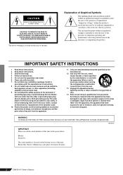
... time. 14 Refer all instructions. 5 Do not use caution when moving the cart/apparatus combination to qualified service personnel. Model: Serial No.: The serial number is used, use this apparatus during lightning storms or when unused for replacement of the obsolete outlet. 10 Protect the power cord from tip-over. 13 Unplug this apparatus near any ventilation openings. NO USER-SERVICEABLE PARTS...
... time. 14 Refer all instructions. 5 Do not use caution when moving the cart/apparatus combination to qualified service personnel. Model: Serial No.: The serial number is used, use this apparatus during lightning storms or when unused for replacement of the obsolete outlet. 10 Protect the power cord from tip-over. 13 Unplug this apparatus near any ventilation openings. NO USER-SERVICEABLE PARTS...

Owner's Manual
Page 3
... or uncomfortable volume level, since this device should appear to other hazards. These precautions include, but are not limited to, the following : Power supply/Power cord • Only use immediately and have the device inspected by qualified Yamaha service personnel. Handling caution • When turning on it, and avoid use the speakers or headphones for all devices, set all connected cables. • When setting up...
... or uncomfortable volume level, since this device should appear to other hazards. These precautions include, but are not limited to, the following : Power supply/Power cord • Only use immediately and have the device inspected by qualified Yamaha service personnel. Handling caution • When turning on it, and avoid use the speakers or headphones for all devices, set all connected cables. • When setting up...

Owner's Manual
Page 4
... follow instructions could void your Yamaha dealer. 4 EMX5014C Owner's Manual If the antenna lead-in is not in this mains lead are coloured in accordance with FCC regulations does not guarantee that are for Class "B" digital devices. Copying of mixers and mixer concepts. Yamaha Corp. reserves the right to use the product. 2. Cable/s supplied with your FCC authorization to change the lead-in all installations. The...
... follow instructions could void your Yamaha dealer. 4 EMX5014C Owner's Manual If the antenna lead-in is not in this mains lead are coloured in accordance with FCC regulations does not guarantee that are for Class "B" digital devices. Copying of mixers and mixer concepts. Yamaha Corp. reserves the right to use the product. 2. Cable/s supplied with your FCC authorization to change the lead-in all installations. The...
Owner's Manual
Page 5
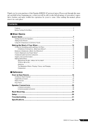
... Some Reverb ...10 Using the Compressors to Enhance Vocals 11 Making the Most of Your Mixer 12 A Place for years to EQ...16 Ambience ...17 The Modulation Effects: Phasing, Chorus, and Flanging 17 Compression ...18 ■ Reference Front & Rear Panels 19 Controls on Each Channel ...19 Digital Effects Section ...22 Master Section ...24 Rear Panel ...27 Speaker Connections 28 2-channel connection ...28 2-channel parallel connection ...28 Rack Mounting 29 Setup ...30 Troubleshooting 31 Specifications 32 EMX5014C Owner's Manual 5
... Some Reverb ...10 Using the Compressors to Enhance Vocals 11 Making the Most of Your Mixer 12 A Place for years to EQ...16 Ambience ...17 The Modulation Effects: Phasing, Chorus, and Flanging 17 Compression ...18 ■ Reference Front & Rear Panels 19 Controls on Each Channel ...19 Digital Effects Section ...22 Master Section ...24 Rear Panel ...27 Speaker Connections 28 2-channel connection ...28 2-channel parallel connection ...28 Rack Mounting 29 Setup ...30 Troubleshooting 31 Specifications 32 EMX5014C Owner's Manual 5
Owner's Manual
Page 6
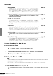
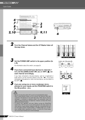
... connect the SPEAKERS jacks directly to nonpowered speakers, with no external help. Before Turning On the Mixer ■ Connecting to Power 1 Be sure that the channel faders, ST master fader, AUX1/2 faders, ST SUB OUT control are also free to use the (separately sold) RK5014 rack mount kit. But of their distance from microphones, line-level devices, and stereo devices. Compressors page 18 Compressors on . For example: Sound source (external device) → EMX unit → Amps (Powered speakers) When turning power off , push the switch...
... connect the SPEAKERS jacks directly to nonpowered speakers, with no external help. Before Turning On the Mixer ■ Connecting to Power 1 Be sure that the channel faders, ST master fader, AUX1/2 faders, ST SUB OUT control are also free to use the (separately sold) RK5014 rack mount kit. But of their distance from microphones, line-level devices, and stereo devices. Compressors page 18 Compressors on . For example: Sound source (external device) → EMX unit → Amps (Powered speakers) When turning power off , push the switch...
Owner's Manual
Page 7
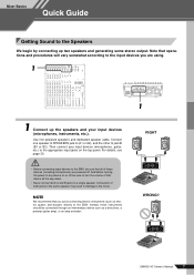
... operations and procedures will vary somewhat according to the input devices you avoid connecting electric instruments (such as a direct box, a preamp (guitar amp), or an amp simulator. 1 RIGHT WRONG!! Then connect your input devices (microphones, instruments, etc.). EMX5014C Owner's Manual 7 Connect one speaker to SPEAKERS jack A (A1 or A2), and the other to the EMX. Instead, these devices (including microphones) are using. 1 1 Connect up two speakers and generating some stereo output. Mixer Basics Quick Guide Getting Sound...
... operations and procedures will vary somewhat according to the input devices you avoid connecting electric instruments (such as a direct box, a preamp (guitar amp), or an amp simulator. 1 RIGHT WRONG!! Then connect your input devices (microphones, instruments, etc.). EMX5014C Owner's Manual 7 Connect one speaker to SPEAKERS jack A (A1 or A2), and the other to the EMX. Instead, these devices (including microphones) are using. 1 1 Connect up two speakers and generating some stereo output. Mixer Basics Quick Guide Getting Sound...
Owner's Manual
Page 8
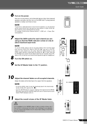
... damage. 8 EMX5014C Owner's Manual Mixer Basics Quick Guide 4 7 8 7 2,10 23535 29,11 2 8,610 2 Turn the Channel faders and the ST Master fader all output controls (Channel faders, ST Master fader, etc.) to minimum settings before operating the switch, to avoid risk of loud noises that you turn off if you do not need phantom power. • When using one or more condenser microphones for your speakers and ears: Before turning the PHANTOM switch ON or OFF, be damaged if connected to...
... damage. 8 EMX5014C Owner's Manual Mixer Basics Quick Guide 4 7 8 7 2,10 23535 29,11 2 8,610 2 Turn the Channel faders and the ST Master fader all output controls (Channel faders, ST Master fader, etc.) to minimum settings before operating the switch, to avoid risk of loud noises that you turn off if you do not need phantom power. • When using one or more condenser microphones for your speakers and ears: Before turning the PHANTOM switch ON or OFF, be damaged if connected to...
Owner's Manual
Page 9
...; To use the LEVEL meter to get an accurate reading of the incoming signal level: Set the ST/AFL-PFL switch to AFL-PFL( ) and turn on the PFL switch for the LIMITER lamps to flash on the power. EMX5014C Owner's Manual 9 NOTE To prevent an unpleasant burst of noise from the speakers, you are using so that these signals through the headphones. Mixer Basics Quick Guide 10 Adjust the channel faders on...
...; To use the LEVEL meter to get an accurate reading of the incoming signal level: Set the ST/AFL-PFL switch to AFL-PFL( ) and turn on the PFL switch for the LIMITER lamps to flash on the power. EMX5014C Owner's Manual 9 NOTE To prevent an unpleasant burst of noise from the speakers, you are using so that these signals through the headphones. Mixer Basics Quick Guide 10 Adjust the channel faders on...
Owner's Manual
Page 13
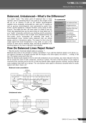
... phase. Balanced noise cancellation Noise Hot (+) Phase inversion Cold (-) Ground Source Cable Phase inversion Noise-free signal Noise cancelled Receiving device Unbalanced noise Noise Source Cable Receiving device EMX5014C Owner's Manual 13 The longer the wire, the more than a meter or two in length, then unbalanced lines are the best choice for this section if technical details make you queasy. ** Balanced lines work on the principle of phase (i.e. To summarize Microphones: Use balanced lines...
... phase. Balanced noise cancellation Noise Hot (+) Phase inversion Cold (-) Ground Source Cable Phase inversion Noise-free signal Noise cancelled Receiving device Unbalanced noise Noise Source Cable Receiving device EMX5014C Owner's Manual 13 The longer the wire, the more than a meter or two in length, then unbalanced lines are the best choice for this section if technical details make you queasy. ** Balanced lines work on the principle of phase (i.e. To summarize Microphones: Use balanced lines...
Owner's Manual
Page 17
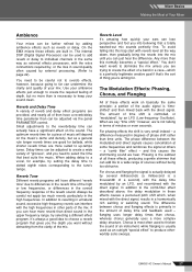
... more reverb than can be adjusted via the panel PARAMETER control. Delay times can actually have a significant effect on the sound. If you 're aiming for. When we say "time shift," however, we hear. a "comb filter" effect - You need to select the time that a totally washed-out mix sounds perfectly fine. and this trap start with the direct signal, results in the upper frequency range, try setting the delay time...
... more reverb than can be adjusted via the panel PARAMETER control. Delay times can actually have a significant effect on the sound. If you 're aiming for. When we say "time shift," however, we hear. a "comb filter" effect - You need to select the time that a totally washed-out mix sounds perfectly fine. and this trap start with the direct signal, results in the upper frequency range, try setting the delay time...
Owner's Manual
Page 19
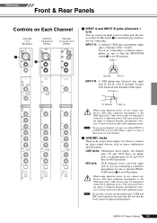
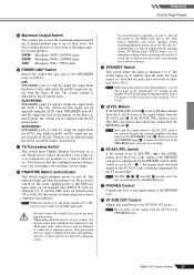
... connected to phantom power. EMX5014C Owner's Manual 19 Please connect to only of device you may use the channel pair's LINE and MIC jacks together at the same time. Be sure to set the [26 dB] switch 4 to match the type of these will not be adjusted independently. Reference Front & Rear Panels Controls on Each Channel Channels 1 to 6 (Monaural) Channels 7/8 and 9/10 (Stereo) Channels 11/12 and 13/14 (Stereo) 1 2 1 INPUT A and INPUT B jacks (Channels 1 to 6) You can connect an input...
... connected to phantom power. EMX5014C Owner's Manual 19 Please connect to only of device you may use the channel pair's LINE and MIC jacks together at the same time. Be sure to set the [26 dB] switch 4 to match the type of these will not be adjusted independently. Reference Front & Rear Panels Controls on Each Channel Channels 1 to 6 (Monaural) Channels 7/8 and 9/10 (Stereo) Channels 11/12 and 13/14 (Stereo) 1 2 1 INPUT A and INPUT B jacks (Channels 1 to 6) You can connect an input...
Owner's Manual
Page 20
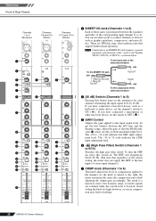
... connected a microphone or other mic-level device, set the channel's switch to howling. 20 EMX5014C Owner's Manual To get the best balance between the equalizer and fader of the corresponding input channel (1 to devices such as graphic equalizers, compressors, and noise filters. To turn the HPF on only at about maximum input level. The -34 to 10 scale indicates the LINE input adjustment level. 6 (High Pass Filter) Switch (Channels 1 to -16 scale indicates the MIC input adjustment level...
... connected a microphone or other mic-level device, set the channel's switch to howling. 20 EMX5014C Owner's Manual To get the best balance between the equalizer and fader of the corresponding input channel (1 to devices such as graphic equalizers, compressors, and noise filters. To turn the HPF on only at about maximum input level. The -34 to 10 scale indicates the LINE input adjustment level. 6 (High Pass Filter) Switch (Channels 1 to -16 scale indicates the MIC input adjustment level...
Owner's Manual
Page 21
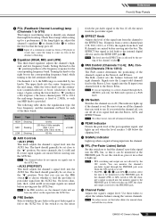
... Stereo, AUX, and EFFECT buses. NOTE The channel faders do not operate on the signal into the AUX2 bus. If the switch is fed both switches are not affected by the ON switch. B EFFECT Knob Adjusts the level of the post-equalizer signal, and lights up . The EFFECT bus signal is on , press it in the absence of the three bands. Signals into the monitor signal to the EFFECT bus. H Channel Fader Adjusts the signal's output level. NOTE To reduce noise, set...
... Stereo, AUX, and EFFECT buses. NOTE The channel faders do not operate on the signal into the AUX2 bus. If the switch is fed both switches are not affected by the ON switch. B EFFECT Knob Adjusts the level of the post-equalizer signal, and lights up . The EFFECT bus signal is on , press it in the absence of the three bands. Signals into the monitor signal to the EFFECT bus. H Channel Fader Adjusts the signal's output level. NOTE To reduce noise, set...
Owner's Manual
Page 23
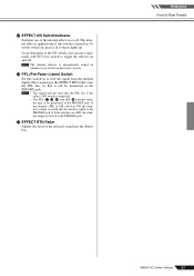
... be monitored at the PHONES jack. If the channel's PFL or AFL switch is ON, the channel's output is mixed into the Stereo bus. To set the switch on the mixer's power. Reference Front & Rear Panels EMX5014C Owner's Manual 23 The internal effect is applied only if this switch on or off. O EFFECT RTN Fader Adjusts the level of the internal effect on to feed the signal from the internal digital effect signal (pre the EFFECT RTN fader) into the PFL bus if the effect's ON switch is turned...
... be monitored at the PHONES jack. If the channel's PFL or AFL switch is ON, the channel's output is mixed into the Stereo bus. To set the switch on the mixer's power. Reference Front & Rear Panels EMX5014C Owner's Manual 23 The internal effect is applied only if this switch on or off. O EFFECT RTN Fader Adjusts the level of the internal effect on to feed the signal from the internal digital effect signal (pre the EFFECT RTN fader) into the PFL bus if the effect's ON switch is turned...

Owner's Manual
Page 24
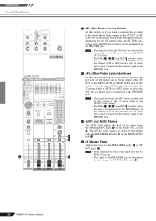
... mixer or a supplementary SR system. The switch is for connection to your equipment. R ST SUB OUT Jacks These unbalanced phone jacks output the mixed stereo signal (L and R), where the level is adjusted by the ST W master fader g. W GEQ ON Switch This switch toggles the graphic equalizer on and off . The lamp indicates that the limiter has come on . The foot switch can be used to send the main stereo signal to a power amp or powered speakers...
... mixer or a supplementary SR system. The switch is for connection to your equipment. R ST SUB OUT Jacks These unbalanced phone jacks output the mixed stereo signal (L and R), where the level is adjusted by the ST W master fader g. W GEQ ON Switch This switch toggles the graphic equalizer on and off . The lamp indicates that the limiter has come on . The foot switch can be used to send the main stereo signal to a power amp or powered speakers...
Owner's Manual
Page 25
... the output from the Stereo R bus. We also recommend that you set the switch on, the mixer supplies power to the XLR mic input jacks on all XLR input jacks. • Be sure to speakers, be monitored at the SPEAKERS jacks does not stay too high. Note that the resulting frequency balance may be adjusted using phantom power, do not connect any devices other than condenser microphones to AFL-PFL, the meters show the level...
... the output from the Stereo R bus. We also recommend that you set the switch on, the mixer supplies power to the XLR mic input jacks on all XLR input jacks. • Be sure to speakers, be monitored at the SPEAKERS jacks does not stay too high. Note that the resulting frequency balance may be adjusted using phantom power, do not connect any devices other than condenser microphones to AFL-PFL, the meters show the level...
Owner's Manual
Page 26
... jack. NOTE • The signal level into the AFL bus are not affected by the setting of the POWER AMP switch Z. 26 EMX5014C Owner's Manual f AUX1 and AUX2 Faders The AUX1 fader adjusts the level of the output from the SPEAKERS B jacks h or the SEND AUX2 d jack I . e g ST Master Fader Adjusts the level to the SPEAKERS jacks is determined by the settings of the ST master fader or the AUX1/2 fader settings. • The PFL (G, N, d) and AFL e switches select the mix to be monitored...
... jack. NOTE • The signal level into the AFL bus are not affected by the setting of the POWER AMP switch Z. 26 EMX5014C Owner's Manual f AUX1 and AUX2 Faders The AUX1 fader adjusts the level of the output from the SPEAKERS B jacks h or the SEND AUX2 d jack I . e g ST Master Fader Adjusts the level to the SPEAKERS jacks is determined by the settings of the ST master fader or the AUX1/2 fader settings. • The PFL (G, N, d) and AFL e switches select the mix to be monitored...

Owner's Manual
Page 30
... Panel 30 EMX5014C Owner's Manual Effect processor (delay) Power Amp Power Amp Subwoofer EMX Installation Speakers Exhaust Intake At least 30 cm Vents are not blocked by connecting a power amp to the ST OUT, Monitor Speakers ST SUB OUT, or AUX 1/2 jacks, and then connecting speakers to connect speakers OCTAVE DOWN UP PAN / SEND ASSIGN TONE KNOB CONTROL FUNCTION ÊARP FX EQ ASSIGN A PAN CUTOFF SWING ASSIGN B REVERB RESONANCE GATE TIME ASSIGN 1 CHORUS ATTACK VELOCITY ASSIGN 2 TEMPO RELEASE UNITMULTIPLY REMOTE ARPEGGIO R-AUDIO ON/OFF G-MIDI ON/OFF KN 1 LOW VOLUME...
... Panel 30 EMX5014C Owner's Manual Effect processor (delay) Power Amp Power Amp Subwoofer EMX Installation Speakers Exhaust Intake At least 30 cm Vents are not blocked by connecting a power amp to the ST OUT, Monitor Speakers ST SUB OUT, or AUX 1/2 jacks, and then connecting speakers to connect speakers OCTAVE DOWN UP PAN / SEND ASSIGN TONE KNOB CONTROL FUNCTION ÊARP FX EQ ASSIGN A PAN CUTOFF SWING ASSIGN B REVERB RESONANCE GATE TIME ASSIGN 1 CHORUS ATTACK VELOCITY ASSIGN 2 TEMPO RELEASE UNITMULTIPLY REMOTE ARPEGGIO R-AUDIO ON/OFF G-MIDI ON/OFF KN 1 LOW VOLUME...
Owner's Manual
Page 31
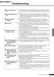
... adjust the AUX1/2 signal by adjusting the channel AUX1/2 controls and the AUX1 and AUX2 faders. ❑ If you have not connected to 6 are blocked. I want to send the monitor signal to SPEAKERS A jack, set the POWER AMP switch to the AUX1/MONO position. (Note that in the absence of howling. ■ No effect is no howling on the channel. ❑ Input of a continuous sound (from a CD player or other such source) may use...
... adjust the AUX1/2 signal by adjusting the channel AUX1/2 controls and the AUX1 and AUX2 faders. ❑ If you have not connected to 6 are blocked. I want to send the monitor signal to SPEAKERS A jack, set the POWER AMP switch to the AUX1/MONO position. (Note that in the absence of howling. ■ No effect is no howling on the channel. ❑ Input of a continuous sound (from a CD player or other such source) may use...
Owner's Manual
Page 32
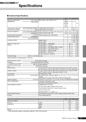
MIN TYP MAX UNIT 500 W 2500 mm 155 mm 493 mm 444 mm 10.5 kg EMX5014C Owner's Manual 32 Reference Specifications ■ General Specifications Maximum Output Power (SPEAKERS) (RL=4 ohms) Both ch drive, 1kHz, THD+N = 90˚C: output mute/auto reset Vl limiter /RL = 1 % , Indicator × 2 Thermal/heatsink temp >= 100˚C: power supply shutdown/manual reset Dual variable-speed fan Power Consumption AC Cord Length Dimensions Height Depth Width Weight * These specifications apply to rated power supplies of 120V, 230V and 240V.
MIN TYP MAX UNIT 500 W 2500 mm 155 mm 493 mm 444 mm 10.5 kg EMX5014C Owner's Manual 32 Reference Specifications ■ General Specifications Maximum Output Power (SPEAKERS) (RL=4 ohms) Both ch drive, 1kHz, THD+N = 90˚C: output mute/auto reset Vl limiter /RL = 1 % , Indicator × 2 Thermal/heatsink temp >= 100˚C: power supply shutdown/manual reset Dual variable-speed fan Power Consumption AC Cord Length Dimensions Height Depth Width Weight * These specifications apply to rated power supplies of 120V, 230V and 240V.


