

Owner's Manual
Page 2
... "TROUBLESHOOTING" section regarding common operating errors before starting the audio source play. Install this manual carefully. Avoid sources of the speaker. Precautions should be held responsible for the plug supplied with this apparatus may interfere with the coloured markings identifying the terminals in a cool, dry, clean place - Do not connect audio component to the terminal which is coloured BROWN must be destroyed, as tuners, receivers and...
... "TROUBLESHOOTING" section regarding common operating errors before starting the audio source play. Install this manual carefully. Avoid sources of the speaker. Precautions should be held responsible for the plug supplied with this apparatus may interfere with the coloured markings identifying the terminals in a cool, dry, clean place - Do not connect audio component to the terminal which is coloured BROWN must be destroyed, as tuners, receivers and...

Owner's Manual
Page 3
... DSP PROGRAM (DIGITAL SOUND FIELD PROCESSOR EFFECT 19 MENU FUNCTIONS 21 REMOTE CONTROL OPERATING OTHER COMPONENTS USING THE REMOTE CONTROL 23 OPERATION REMOTE CONTROL APPENDIX APPENDIX GLOSSARY 28 TROUBLESHOOTING 29 SPECIFICATIONS 30 INDEX 31 Manufactured under license from movies, to concerts, and sporting events. y indicates a tip for your operation. 1 English You can reproduce the sound field of a subwoofer and two rear speakers. q Includes Dolby Digital* and Dolby Pro Logic Decoder This system can also enjoy stronger bass and surround...
... DSP PROGRAM (DIGITAL SOUND FIELD PROCESSOR EFFECT 19 MENU FUNCTIONS 21 REMOTE CONTROL OPERATING OTHER COMPONENTS USING THE REMOTE CONTROL 23 OPERATION REMOTE CONTROL APPENDIX APPENDIX GLOSSARY 28 TROUBLESHOOTING 29 SPECIFICATIONS 30 INDEX 31 Manufactured under license from movies, to concerts, and sporting events. y indicates a tip for your operation. 1 English You can reproduce the sound field of a subwoofer and two rear speakers. q Includes Dolby Digital* and Dolby Pro Logic Decoder This system can also enjoy stronger bass and surround...

Owner's Manual
Page 6
... subwoofer's power when a YAMAHA subwoofer and rear speakers NX-SW70 (sold separately) are connected. NAMES OF ALL PARTS Front Speaker Unit (Front Panel) INPUT selector button (page 17) DSP selector button (page 20) VOLUME +/- (page 17) STANDBY indicator POWER (page 17) Turns the unit's power on the remote control. This button also turns off . Display VIRTUAL indicator (page 20) TRUBASS indicator (page 18) ENHANCED indicator VIRTUAL TRUBASS DIGITAL ENHANCED SURROUND PRO LOGIC DSP Processing indicators (page 20) Display used for DSP program...
... subwoofer's power when a YAMAHA subwoofer and rear speakers NX-SW70 (sold separately) are connected. NAMES OF ALL PARTS Front Speaker Unit (Front Panel) INPUT selector button (page 17) DSP selector button (page 20) VOLUME +/- (page 17) STANDBY indicator POWER (page 17) Turns the unit's power on the remote control. This button also turns off . Display VIRTUAL indicator (page 20) TRUBASS indicator (page 18) ENHANCED indicator VIRTUAL TRUBASS DIGITAL ENHANCED SURROUND PRO LOGIC DSP Processing indicators (page 20) Display used for DSP program...
Owner's Manual
Page 11
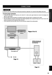
... time that wiring has been made properly. OPERATION REMOTE CONTROL TV (monitor) DVD player, LD player, etc. PREPARATION CONNECTIONS CAUTION Always be sure to turn off the power of connection and terminal names differ depending on the component being used, be connected when making connections. Pages 10 to the right "R"(red) terminal. • Insert the plug securely. To ensure proper connections • Connect the white plug of the connection cord to the left "L" (white) audio signal...
... time that wiring has been made properly. OPERATION REMOTE CONTROL TV (monitor) DVD player, LD player, etc. PREPARATION CONNECTIONS CAUTION Always be sure to turn off the power of connection and terminal names differ depending on the component being used, be connected when making connections. Pages 10 to the right "R"(red) terminal. • Insert the plug securely. To ensure proper connections • Connect the white plug of the connection cord to the left "L" (white) audio signal...
Owner's Manual
Page 12
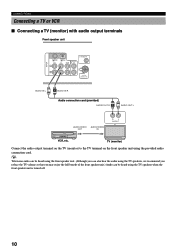
CONNECTIONS Connecting a TV or VCR s Connecting a TV (monitor) with audio output terminals Front speaker unit INPUT MARK DIGITAL 2 ( /PCM) AUX L DIGITAL 1 ( /PCM) TV VIDEO THROUGH OUT SUBWOOFER R SYSTEM CONNECTOR AUDIO IN L L R AUDIO IN R Audio connection cord (provided) AUDIO OUT R R L AUDIO OUT L AUDIO/VIDEO AUDIO/VIDEO OUT IN R L OUTPUT VCR, etc. TV (monitor) Connect the audio output terminal on the TV (monitor) to the TV terminal on the front speaker unit using the TV speakers when the front speaker unit is turned off. 10 y Television audio can be heard using the...
CONNECTIONS Connecting a TV or VCR s Connecting a TV (monitor) with audio output terminals Front speaker unit INPUT MARK DIGITAL 2 ( /PCM) AUX L DIGITAL 1 ( /PCM) TV VIDEO THROUGH OUT SUBWOOFER R SYSTEM CONNECTOR AUDIO IN L L R AUDIO IN R Audio connection cord (provided) AUDIO OUT R R L AUDIO OUT L AUDIO/VIDEO AUDIO/VIDEO OUT IN R L OUTPUT VCR, etc. TV (monitor) Connect the audio output terminal on the TV (monitor) to the TV terminal on the front speaker unit using the TV speakers when the front speaker unit is turned off. 10 y Television audio can be heard using the...

Owner's Manual
Page 13
...addition to a TV (monitor) without audio output terminals Front speaker unit CONNECTIONS INPUT MARK DIGITAL 2 ( /PCM) AUX L DIGITAL 1 ( /PCM) TV VIDEO THROUGH OUT SUBWOOFER R SYSTEM CONNECTOR Audio connection cord (provided) AUDIO L IN L R AUDIO IN R AUDIO THROUGH R OUT R AUDIO R OUT R L AUDIO OUT L AUDIO L THROUGH OUT L AUDIO IN R R Audio connection cord (commercially available) L AUDIO IN L R L OUTPUT VIDEO OUT VIDEO IN R L INPUT VCR, etc. VCR audio may always be heard when the front speaker unit's power is turned off . REMOTE CONTROL APPENDIX English 11...
...addition to a TV (monitor) without audio output terminals Front speaker unit CONNECTIONS INPUT MARK DIGITAL 2 ( /PCM) AUX L DIGITAL 1 ( /PCM) TV VIDEO THROUGH OUT SUBWOOFER R SYSTEM CONNECTOR Audio connection cord (provided) AUDIO L IN L R AUDIO IN R AUDIO THROUGH R OUT R AUDIO R OUT R L AUDIO OUT L AUDIO L THROUGH OUT L AUDIO IN R R Audio connection cord (commercially available) L AUDIO IN L R L OUTPUT VIDEO OUT VIDEO IN R L INPUT VCR, etc. VCR audio may always be heard when the front speaker unit's power is turned off . REMOTE CONTROL APPENDIX English 11...
Owner's Manual
Page 14
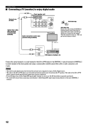
... front speaker unit's power is not in the terminal when the terminal is turned off. • If your LD player's Dolby Digital RF signal output terminal directly to this unit and your component to enjoy a Dolby Digital source. • The audio of dust.) VIDEO IN COAXIAL DIGITAL OUTPUT OPTICAL DIGITAL VIDEO OUT DVD player, LD player, etc. CONNECTIONS s Connecting a TV (monitor) to enjoy digital audio Connect one of the front speaker unit using a commercially available optical fiber cable or audio connection cord (1 pin). Connect the optical terminal or coaxial terminal...
... front speaker unit's power is not in the terminal when the terminal is turned off. • If your LD player's Dolby Digital RF signal output terminal directly to this unit and your component to enjoy a Dolby Digital source. • The audio of dust.) VIDEO IN COAXIAL DIGITAL OUTPUT OPTICAL DIGITAL VIDEO OUT DVD player, LD player, etc. CONNECTIONS s Connecting a TV (monitor) to enjoy digital audio Connect one of the front speaker unit using a commercially available optical fiber cable or audio connection cord (1 pin). Connect the optical terminal or coaxial terminal...
Owner's Manual
Page 15
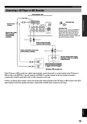
... optical fiber cable or audio connection cord (1 pin). CD player, MD recorder, etc. If there is not in the terminal when the terminal is no digital output terminal. Safely store the cap and always re-insert it in use. (This cap prevents the entrance of these Optical fiber cable (EIA standard) (commercially available) INPUT MARK DIGITAL 2 ( /PCM) AUX L DIGITAL 1 ( /PCM) TV VIDEO THROUGH OUT SUBWOOFER R SYSTEM CONNECTOR AUDIO IN L L R AUDIO IN R Audio connection cord...
... optical fiber cable or audio connection cord (1 pin). CD player, MD recorder, etc. If there is not in the terminal when the terminal is no digital output terminal. Safely store the cap and always re-insert it in use. (This cap prevents the entrance of these Optical fiber cable (EIA standard) (commercially available) INPUT MARK DIGITAL 2 ( /PCM) AUX L DIGITAL 1 ( /PCM) TV VIDEO THROUGH OUT SUBWOOFER R SYSTEM CONNECTOR AUDIO IN L L R AUDIO IN R Audio connection cord...

Owner's Manual
Page 16
... 14 Connecting a YAMAHA subwoofer and rear speakers NX-SW70 (sold separately) To SYSTEM CONNECTOR terminal INPUT MARK DIGITAL 2 ( /PCM) AUX L DIGITAL 1 ( /PCM) TV VIDEO THROUGH OUT SUBWOOFER R SYSTEM CONNECTOR System connector cable provided with the YAMAHA NX-SW70 To SYSTEM CONNECTOR terminal Match the b mark on the plug with the a mark on the front speaker unit using a commercially available audio connection cord (1 pin). • For details regarding connections, please refer to enjoy powerful bass tones...
... 14 Connecting a YAMAHA subwoofer and rear speakers NX-SW70 (sold separately) To SYSTEM CONNECTOR terminal INPUT MARK DIGITAL 2 ( /PCM) AUX L DIGITAL 1 ( /PCM) TV VIDEO THROUGH OUT SUBWOOFER R SYSTEM CONNECTOR System connector cable provided with the YAMAHA NX-SW70 To SYSTEM CONNECTOR terminal Match the b mark on the plug with the a mark on the front speaker unit using a commercially available audio connection cord (1 pin). • For details regarding connections, please refer to enjoy powerful bass tones...

Owner's Manual
Page 17
... by pressing POWER on the power by following order. LEFT SURROUND RIGHT SURROUND Rear speakers REMOTE CONTROL APPENDIX English 15 Speaker output levels may be output in the 1 following the steps. 2 Press TEST. If the STANDBY indicator is lit, turn on the front speaker unit. PREPARATION OPERATION ADJUSTING THE SPEAKER OUTPUT LEVELS When reproducing a Dolby Surround source using a DSP program such as DOLBY PRO LOGIC or DOLBY DIGITAL ENHANCED, it is possible to bring out the full digital effect of the sound field...
... by pressing POWER on the power by following order. LEFT SURROUND RIGHT SURROUND Rear speakers REMOTE CONTROL APPENDIX English 15 Speaker output levels may be output in the 1 following the steps. 2 Press TEST. If the STANDBY indicator is lit, turn on the front speaker unit. PREPARATION OPERATION ADJUSTING THE SPEAKER OUTPUT LEVELS When reproducing a Dolby Surround source using a DSP program such as DOLBY PRO LOGIC or DOLBY DIGITAL ENHANCED, it is possible to bring out the full digital effect of the sound field...

Owner's Manual
Page 19
... switched in the order: VIDEO → TV → AUX → DIGITAL 1 → DIGITAL 2. or 3 Adjust the level using p on the remote control. or Front panel Remote control Front panel or Remote control REMOTE CONTROL APPENDIX English 17 PREPARATION OPERATION OPERATION OPERATING THE UNIT Enjoying the Home Theater Sound System This section describes how to select audio output from A/V component such as a TV, VCR, or DVD, LD, CD player, or MD recorder as input source to the Home Theater Sound System AV-S70 and how to turn on the power using VOLUME...
... switched in the order: VIDEO → TV → AUX → DIGITAL 1 → DIGITAL 2. or 3 Adjust the level using p on the remote control. or Front panel Remote control Front panel or Remote control REMOTE CONTROL APPENDIX English 17 PREPARATION OPERATION OPERATION OPERATING THE UNIT Enjoying the Home Theater Sound System This section describes how to select audio output from A/V component such as a TV, VCR, or DVD, LD, CD player, or MD recorder as input source to the Home Theater Sound System AV-S70 and how to turn on the power using VOLUME...
Owner's Manual
Page 21
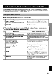
... movie sound as DOLBY DIGITAL, DOLBY PRO LOGIC, or YAMAHA CINEMA DSP. For reproduction of the rich, full sound found in which dialog and sound effects are used for the reproduction of operas and other location by selecting from any of seven DSP programs best suited to the source being reproduced. For the wide area sound field effect of the Dolby Digital or Dolby Surround signal. REMOTE CONTROL APPENDIX English 19 Program name 1 VIRTUAL SURROUND (input source: Dolby Digital or Dolby Surround...
... movie sound as DOLBY DIGITAL, DOLBY PRO LOGIC, or YAMAHA CINEMA DSP. For reproduction of the rich, full sound found in which dialog and sound effects are used for the reproduction of operas and other location by selecting from any of seven DSP programs best suited to the source being reproduced. For the wide area sound field effect of the Dolby Digital or Dolby Surround signal. REMOTE CONTROL APPENDIX English 19 Program name 1 VIRTUAL SURROUND (input source: Dolby Digital or Dolby Surround...

Owner's Manual
Page 22
... minimize the volume level of input signal when reproducing a source using the DSP selector button on page 28. 20 or Front panel Remote control Each time this button again will be selected in memory so that you feel sounds best for each input source (AUX, TV, VIDEO, DIGITAL 1, and DIGITAL 2) is connected: VIRTUAL SURROUND MONO MOVIE DSP OFF q When the front speaker unit and a YAMAHA subwoofer and rear speakers NX-SW70 are used for a source regardless of its name. q DIGITAL: Lights when reproducing a source encoded...
... minimize the volume level of input signal when reproducing a source using the DSP selector button on page 28. 20 or Front panel Remote control Each time this button again will be selected in memory so that you feel sounds best for each input source (AUX, TV, VIDEO, DIGITAL 1, and DIGITAL 2) is connected: VIRTUAL SURROUND MONO MOVIE DSP OFF q When the front speaker unit and a YAMAHA subwoofer and rear speakers NX-SW70 are used for a source regardless of its name. q DIGITAL: Lights when reproducing a source encoded...

Owner's Manual
Page 23
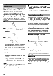
...OPERATION MENU FUNCTIONS The menu functions include: "Auto Power" for setting automatic power on/off the power. (The STANDBY indicator will slowly flash.) 3. Adjustments on again using the Auto Power function. Auto Power Off automatically shuts off , "Dimmer" for adjusting display brightness, "Input Name" for naming input, and "Delay Time" for adjusting the delay time used for surround sound. Pressing + will cycle through the selections from bottom to the table given below . 1. When Auto Power On results even though no buttons have been operated for the Auto Power function or turn...
...OPERATION MENU FUNCTIONS The menu functions include: "Auto Power" for setting automatic power on/off the power. (The STANDBY indicator will slowly flash.) 3. Adjustments on again using the Auto Power function. Auto Power Off automatically shuts off , "Dimmer" for adjusting display brightness, "Input Name" for naming input, and "Delay Time" for adjusting the delay time used for surround sound. Pressing + will cycle through the selections from bottom to the table given below . 1. When Auto Power On results even though no buttons have been operated for the Auto Power function or turn...
Owner's Manual
Page 24
... AUX, DIGITAL 1 and DIGITAL 2 input terminals. (It is not possible to change the input names for the TV or VIDEO input terminals.) This function makes selecting input source easier by allowing you to give names to AUX, DIGITAL 1 and DIGITAL 2 input terminals. to display "Delay Time". 3 Press MENU + or - CAUTION The variable sound intensity range is possible to adjust the delay time. To cancel the menu functions, press MENU until the input display returns. AUX AUX: VIDEO2 AUX: CABLE AUX: GAME AUX: SAT AUX: MD AUX: CD AUX: LD AUX: DVD...
... AUX, DIGITAL 1 and DIGITAL 2 input terminals. (It is not possible to change the input names for the TV or VIDEO input terminals.) This function makes selecting input source easier by allowing you to give names to AUX, DIGITAL 1 and DIGITAL 2 input terminals. to display "Delay Time". 3 Press MENU + or - CAUTION The variable sound intensity range is possible to adjust the delay time. To cancel the menu functions, press MENU until the input display returns. AUX AUX: VIDEO2 AUX: CABLE AUX: GAME AUX: SAT AUX: MD AUX: CD AUX: LD AUX: DVD...

Owner's Manual
Page 25
... indicator flashes and then goes out.) Refer to be controlled turns on and off. 23 English The signals for controlling the front speaker unit have already been set for the S70 button so that only the manufacturer code for the TV, VCR or SAT needs to be controlled. Notes • Remote control of this problem, please use the numeric buttons to enter the 4-digit 3 manufacturer code for the component...
... indicator flashes and then goes out.) Refer to be controlled turns on and off. 23 English The signals for controlling the front speaker unit have already been set for the S70 button so that only the manufacturer code for the TV, VCR or SAT needs to be controlled. Notes • Remote control of this problem, please use the numeric buttons to enter the 4-digit 3 manufacturer code for the component...

Owner's Manual
Page 27
... selected when setting the manufacturer code. • If more than one code is turned off . PREPARATION OPERATION OPERATING OTHER COMPONENTS USING THE REMOTE CONTROL 7 Press the remote control selector button you pressed in the order given. • Remove and replace the remote control's batteries (complete this indicates that auto preset cannot be performed for a manufacturer, try performing manual preset. Transmission 6 indicator 7 The indicator will not be set properly. If the transmission indicator flashes...
... selected when setting the manufacturer code. • If more than one code is turned off . PREPARATION OPERATION OPERATING OTHER COMPONENTS USING THE REMOTE CONTROL 7 Press the remote control selector button you pressed in the order given. • Remove and replace the remote control's batteries (complete this indicates that auto preset cannot be performed for a manufacturer, try performing manual preset. Transmission 6 indicator 7 The indicator will not be set properly. If the transmission indicator flashes...

Owner's Manual
Page 30
... channels (three front and one rear channel. Using a built-in directions other objects to arrive at the ear slightly delayed (early reflection). s Sound field Not all 5.1 channels, Dolby Digital can be used to make sound move from virtual speakers located in YAMAHA DSP (digital sound field processor) to create sound fields, this front speaker unit allows you to freely select various sound field programs created from the sound source directly into two-channel stereo and separates them using...
... channels (three front and one rear channel. Using a built-in directions other objects to arrive at the ear slightly delayed (early reflection). s Sound field Not all 5.1 channels, Dolby Digital can be used to make sound move from virtual speakers located in YAMAHA DSP (digital sound field processor) to create sound fields, this front speaker unit allows you to freely select various sound field programs created from the sound source directly into two-channel stereo and separates them using...

Owner's Manual
Page 31
.... The STANDBY indicator flashes slowly. Try inverting the right-left polarity of the power cord and re-insert into the AC outlet. • The unit is in the tuner or TV and the video image is noise in Auto Power Off mode. Use of time. • Is a tuner or TV that uses an indoor antenna located near the unit? Select the other component. Cannot control other program. Refer...
.... The STANDBY indicator flashes slowly. Try inverting the right-left polarity of the power cord and re-insert into the AC outlet. • The unit is in the tuner or TV and the video image is noise in Auto Power Off mode. Use of time. • Is a tuner or TV that uses an indoor antenna located near the unit? Select the other component. Cannot control other program. Refer...

Owner's Manual
Page 33
... Adjusting the bass (subwoofer level 18 Adjusting the delay time 22 Adjusting the volume level 17 Automatically setting a manufacturer code 24 Auto Power → Setting auto power on/off 21 AUX terminal 13 C CINEMA DSP → DSP program 19 Connecting a CD player 13 Connecting a DVD player 12 Connecting a subwoofer and rear speakers 14 Connecting a TV 10, 11 Connecting a VCR 10, 11 Connecting an LD player 12 Connecting an MD recorder 13 Connecting the AC power supply cord 14 Controlling a TV with the remote control 26 Controlling a VCR with the remote control 27 D Delay time...
... Adjusting the bass (subwoofer level 18 Adjusting the delay time 22 Adjusting the volume level 17 Automatically setting a manufacturer code 24 Auto Power → Setting auto power on/off 21 AUX terminal 13 C CINEMA DSP → DSP program 19 Connecting a CD player 13 Connecting a DVD player 12 Connecting a subwoofer and rear speakers 14 Connecting a TV 10, 11 Connecting a VCR 10, 11 Connecting an LD player 12 Connecting an MD recorder 13 Connecting the AC power supply cord 14 Controlling a TV with the remote control 26 Controlling a VCR with the remote control 27 D Delay time...


