

Owners Manual
Page 3
... separate components. C-2 Control Amplifier Received top prize at the Milan International Music and HiFi Show. NS-690 Natural Sound Speaker NS-1000M Monitor Speaker A truly legendary speaker still revered by HiFi enthusiasts. NS-690 B-1 PX-2 B-6 B-6 Power Amplifier Pyramid-shaped power amplifier. GT-2000/L Turntable First CD Player (CD-1) introduced in 1967 NS-20 Monitor Speaker CA-1000 Integrated Amplifier Featuring A-Class operation, the CA-1000 set the standard for integrated amplifiers. NS-20 Natural Sound Speaker Series...
... separate components. C-2 Control Amplifier Received top prize at the Milan International Music and HiFi Show. NS-690 Natural Sound Speaker NS-1000M Monitor Speaker A truly legendary speaker still revered by HiFi enthusiasts. NS-690 B-1 PX-2 B-6 B-6 Power Amplifier Pyramid-shaped power amplifier. GT-2000/L Turntable First CD Player (CD-1) introduced in 1967 NS-20 Monitor Speaker CA-1000 Integrated Amplifier Featuring A-Class operation, the CA-1000 set the standard for integrated amplifiers. NS-20 Natural Sound Speaker Series...

Owners Manual
Page 4
... & Balance power amplifier circuit ◆ Parallel volume and tone control ◆ Large power supply with four separate circuits ◆ Left-right symmetrical design with rigid, stable construction ◆ Discrete phono amplifier ■ Supplied accessories Please check that you have received all of the following parts. • Remote control • Batteries (AAA, R03, UM-4) (×2) • Power cable • SAFETY BROCHURE Contents Controls and functions...6 Connections...16 Appendix...24 Troubleshooting...
... & Balance power amplifier circuit ◆ Parallel volume and tone control ◆ Large power supply with four separate circuits ◆ Left-right symmetrical design with rigid, stable construction ◆ Discrete phono amplifier ■ Supplied accessories Please check that you have received all of the following parts. • Remote control • Batteries (AAA, R03, UM-4) (×2) • Power cable • SAFETY BROCHURE Contents Controls and functions...6 Connections...16 Appendix...24 Troubleshooting...
Owners Manual
Page 6
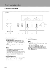
... jack Connects your headphones. Lit dimly: Shows that the power of the unit is ON. If the unit is not to be operated for a long time, set the STANDBY/ON, OFF switch to the SPEAKERS L/R CH terminals are plugged in: - Notes • When headphones are turned off this unit is in STANDBY mode. No signals are plugged into the PHONES jack while MAIN DIRECT is selected as the input source...
... jack Connects your headphones. Lit dimly: Shows that the power of the unit is ON. If the unit is not to be operated for a long time, set the STANDBY/ON, OFF switch to the SPEAKERS L/R CH terminals are plugged in: - Notes • When headphones are turned off this unit is in STANDBY mode. No signals are plugged into the PHONES jack while MAIN DIRECT is selected as the input source...
Owners Manual
Page 7
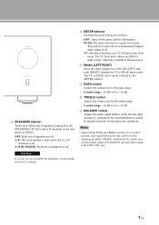
..., audio signal bypasses the tone control circuitry. • Adjusting the BASS, TREBLE, and BALANCE controls does not affect input signals at the MAIN IN jack and output signals at the LINE 2 REC jack. OFF: Both sets of speakers are on. 5 METER selector Switches the meter function as follows. VU: The meter functions as a peak level meter. Control range: -10 dB to 0 to +10 dB 9 BALANCE control Adjusts the audio output balance of the left (LEFT) and right (RIGHT) channels in...
..., audio signal bypasses the tone control circuitry. • Adjusting the BASS, TREBLE, and BALANCE controls does not affect input signals at the MAIN IN jack and output signals at the LINE 2 REC jack. OFF: Both sets of speakers are on. 5 METER selector Switches the meter function as follows. VU: The meter functions as a peak level meter. Control range: -10 dB to 0 to +10 dB 9 BALANCE control Adjusts the audio output balance of the left (LEFT) and right (RIGHT) channels in...

Owners Manual
Page 8
... input source, the audio signals are also output at the LINE 2 REC jacks. 8 En PHONO: Selects the turntable connected to the TUNER jacks. A INPUT selector/indicator Selects the input source. The audio signals of the input source selected with the INPUT selector lights. When MAIN DIRECT is selected, the audio signals are not output at the LINE 2 REC jacks. TUNER: Selects the tuner connected to the PHONO jacks. CD: Selects the CD player connected to 9) 0 A 0 Remote control sensor Receives signals from the remote control. Controls and functions ■ Front panel...
... input source, the audio signals are also output at the LINE 2 REC jacks. 8 En PHONO: Selects the turntable connected to the TUNER jacks. A INPUT selector/indicator Selects the input source. The audio signals of the input source selected with the INPUT selector lights. When MAIN DIRECT is selected, the audio signals are not output at the LINE 2 REC jacks. TUNER: Selects the tuner connected to the PHONO jacks. CD: Selects the CD player connected to 9) 0 A 0 Remote control sensor Receives signals from the remote control. Controls and functions ■ Front panel...

Owners Manual
Page 9
... amplifier connected to the previous volume level. Adjust the volume level using the volume control on the remote control to reduce the current volume level by approximately 20 dB. Press again to restore the audio output to the MAIN IN jacks. 9 En Note The VOLUME control does not affect when you select MAIN DIRECT as the input source. This does not affect the output level at the LINE 2 REC jacks. C AUDIO MUTE indicator Lights when the mute function is turned...
... amplifier connected to the previous volume level. Adjust the volume level using the volume control on the remote control to reduce the current volume level by approximately 20 dB. Press again to restore the audio output to the MAIN IN jacks. 9 En Note The VOLUME control does not affect when you select MAIN DIRECT as the input source. This does not affect the output level at the LINE 2 REC jacks. C AUDIO MUTE indicator Lights when the mute function is turned...
Owners Manual
Page 10
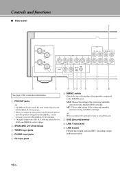
... the PHONO jacks. Controls and functions ■ Rear panel 1 2 3 See page 16 for connection information. 1 PRE OUT jacks y • The PRE OUT jacks output the same channel signal as the SPEAKERS L/R CH terminals. • When you replace the cartridge, be sure to turn off this unit. 7 GND (Ground) terminal 8 LINE 1 input jacks 9 LINE 2 jacks PB (playback) input jacks and REC (recording) output jacks are affected by the BASS and TREBLE control settings. 2 SPEAKERS L/R CH terminals 3 TUNER input jacks 4 PHONO input jacks 5 CD input jacks 4 56 7 8 9 0 6 MM/MC switch Selects...
... the PHONO jacks. Controls and functions ■ Rear panel 1 2 3 See page 16 for connection information. 1 PRE OUT jacks y • The PRE OUT jacks output the same channel signal as the SPEAKERS L/R CH terminals. • When you replace the cartridge, be sure to turn off this unit. 7 GND (Ground) terminal 8 LINE 1 input jacks 9 LINE 2 jacks PB (playback) input jacks and REC (recording) output jacks are affected by the BASS and TREBLE control settings. 2 SPEAKERS L/R CH terminals 3 TUNER input jacks 4 PHONO input jacks 5 CD input jacks 4 56 7 8 9 0 6 MM/MC switch Selects...

Owners Manual
Page 11
.... Adjust the volume level using the volume control on the connection, see page 19. B TRIGGER IN jack Use this inlet to plug in the supplied power cable. For details on the external amplifier connected to the MAIN IN jacks when you select MAIN DIRECT as the input source. E AC IN inlet Use this jack to connect an external component for the trigger function. A AUTO POWER STANDBY switch ON: The unit enters STANDBY mode automatically if not operated for 8 hours. C REMOTE IN/OUT jacks Use...
.... Adjust the volume level using the volume control on the connection, see page 19. B TRIGGER IN jack Use this inlet to plug in the supplied power cable. For details on the external amplifier connected to the MAIN IN jacks when you select MAIN DIRECT as the input source. E AC IN inlet Use this jack to connect an external component for the trigger function. A AUTO POWER STANDBY switch ON: The unit enters STANDBY mode automatically if not operated for 8 hours. C REMOTE IN/OUT jacks Use...

Owners Manual
Page 12
... 2 3 PHONO MAIN DIRECT CD TUNER BAND 5 4 PRESET SOURCE LAYER VOLUME 6 1 Infrared signal transmitter Outputs infrared control signals. 2 p AMP key Turns this unit ON or switches it to the MAIN IN jacks. For details on the remote control. MAIN DIRECT: Selects the component connected to STANDBY mode. MUTE 7 12 En The audio signals of your tuner for details. y When LINE 2 is selected as the input source, the audio signals are not output at the LINE 2 REC jacks. When MAIN DIRECT is selected as the input source, the audio signals...
... 2 3 PHONO MAIN DIRECT CD TUNER BAND 5 4 PRESET SOURCE LAYER VOLUME 6 1 Infrared signal transmitter Outputs infrared control signals. 2 p AMP key Turns this unit ON or switches it to the MAIN IN jacks. For details on the remote control. MAIN DIRECT: Selects the component connected to STANDBY mode. MUTE 7 12 En The audio signals of your tuner for details. y When LINE 2 is selected as the input source, the audio signals are not output at the LINE 2 REC jacks. When MAIN DIRECT is selected as the input source, the audio signals...
Owners Manual
Page 13
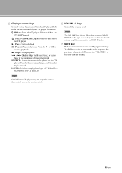
.... 6 VOLUME +/- Adjust the volume level on the CD player. key also cancels muting. LAYER: Switches the playback layer of the CD player. (Play): Starts playback. (Pause): Pauses playback. The playback source changes each time this key is pressed. Pressing the VOLUME + or - SOURCE: Selects the source to be played on the external amplifier connected to the owner's manual of Yamaha CD player. Press again to restore the audio output to STANDBY mode. 5 CD player control keys Control various functions of...
.... 6 VOLUME +/- Adjust the volume level on the CD player. key also cancels muting. LAYER: Switches the playback layer of the CD player. (Play): Starts playback. (Pause): Pauses playback. The playback source changes each time this key is pressed. Pressing the VOLUME + or - SOURCE: Selects the source to be played on the external amplifier connected to the owner's manual of Yamaha CD player. Press again to restore the audio output to STANDBY mode. 5 CD player control keys Control various functions of...

Owners Manual
Page 14
Be sure to the polarity markings (+ and -) on the front panel of the remote control Approximately 6 m (20 ft) 30 30 1 2 y The remote control transmits a directional infrared beam. Controls and functions ■ Installing batteries in the remote control 1 Remove the battery compartment cover. 2 Insert the two batteries (AAA, R03, UM-4) according to aim the remote control directly at the remote control sensor on the inside of the battery compartment. ■ Operating range of this unit during operation. 3 Reinstall the battery compartment cover. 3 14 En
Be sure to the polarity markings (+ and -) on the front panel of the remote control Approximately 6 m (20 ft) 30 30 1 2 y The remote control transmits a directional infrared beam. Controls and functions ■ Installing batteries in the remote control 1 Remove the battery compartment cover. 2 Insert the two batteries (AAA, R03, UM-4) according to aim the remote control directly at the remote control sensor on the inside of the battery compartment. ■ Operating range of this unit during operation. 3 Reinstall the battery compartment cover. 3 14 En

Owners Manual
Page 16
... components except speakers. • Connect your components. • Use RCA unbalanced cables to connect other or do not let them touch any metal part of this unit and/or the speakers. • All connections must be unnatural and lack bass. Connections Speakers A (R channel) Tuner +- However, you may hear less noise without the connection to reduce noise in the signal. This could damage this unit. Ground Speakers B (R channel) Turntable BD player...
... components except speakers. • Connect your components. • Use RCA unbalanced cables to connect other or do not let them touch any metal part of this unit and/or the speakers. • All connections must be unnatural and lack bass. Connections Speakers A (R channel) Tuner +- However, you may hear less noise without the connection to reduce noise in the signal. This could damage this unit. Ground Speakers B (R channel) Turntable BD player...

Owners Manual
Page 17
... connecting with no volume control, such as a CD player, to the MAIN IN jacks, as the volume level of the signals input to the SPEAKERS L/R CH terminal. If such equipment is connected, a sound may burst, and the unit and/or speaker may be damaged. + - inverted (cross connection, Fig. 2). - External amplifier or active subwoofer Speakers A (L channel) +- -+ CD recorder, tape deck, etc. Preamplifier, AV receiver, etc. Connecting with the left channel "-" terminal and the right channel...
... connecting with no volume control, such as a CD player, to the MAIN IN jacks, as the volume level of the signals input to the SPEAKERS L/R CH terminal. If such equipment is connected, a sound may burst, and the unit and/or speaker may be damaged. + - inverted (cross connection, Fig. 2). - External amplifier or active subwoofer Speakers A (L channel) +- -+ CD recorder, tape deck, etc. Preamplifier, AV receiver, etc. Connecting with the left channel "-" terminal and the right channel...

Owners Manual
Page 19
... connections are complete, and then plug in the power cable to the other pair. to separate the LPF (low pass filter) and HPF (high pass filter) crossovers. Rear panel of A-S1100 Rear panel of A-S1100 Speaker SPEAKERS R CH + A + B Supplied power cable Caution To use the bi-wire connections, switch the SPEAKERS selector on the front panel to be 8 or higher. y To use the bi-wire connections, the impedance of terminals allow the speaker to the A+B BI-WIRING...
... connections are complete, and then plug in the power cable to the other pair. to separate the LPF (low pass filter) and HPF (high pass filter) crossovers. Rear panel of A-S1100 Rear panel of A-S1100 Speaker SPEAKERS R CH + A + B Supplied power cable Caution To use the bi-wire connections, switch the SPEAKERS selector on the front panel to be 8 or higher. y To use the bi-wire connections, the impedance of terminals allow the speaker to the A+B BI-WIRING...
Owners Manual
Page 20
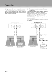
... can be connected. Rear panel of A-S1100 TRIGGER REMOTE SYSTEM CONNECTOR IN IN OUT Infrared receiver Infrared transmitter Infrared receiver Monaural mini-plug cable REMOTE IN OUT Remote control External component (CD player, etc.) Remote control Yamaha component (up to three Yamaha components (including this unit) can transmit remote signals by connecting an infrared receiver and the REMOTE IN jack of the other component to the REMOTE IN/OUT jacks of this unit, using the supplied remote control located in another Yamaha component supporting remote connection, as this...
... can be connected. Rear panel of A-S1100 TRIGGER REMOTE SYSTEM CONNECTOR IN IN OUT Infrared receiver Infrared transmitter Infrared receiver Monaural mini-plug cable REMOTE IN OUT Remote control External component (CD player, etc.) Remote control Yamaha component (up to three Yamaha components (including this unit) can transmit remote signals by connecting an infrared receiver and the REMOTE IN jack of the other component to the REMOTE IN/OUT jacks of this unit, using the supplied remote control located in another Yamaha component supporting remote connection, as this...

Owners Manual
Page 21
.../ STANDBY or MAIN DIRECT input selection). Connect the PRE OUT jacks and the TRIGGER OUT jack of the Yamaha AV receiver to the MAIN IN jacks. Note To enable synchronization, turn off . When MAIN DIRECT is selected as the input source, this unit can be activated when the STANDBY/ON, OFF switch of the unit has been set to OFF. 21 En ■ Connecting a component supporting the trigger function such as a Yamaha AV receiver The operations...
.../ STANDBY or MAIN DIRECT input selection). Connect the PRE OUT jacks and the TRIGGER OUT jack of the Yamaha AV receiver to the MAIN IN jacks. Note To enable synchronization, turn off . When MAIN DIRECT is selected as the input source, this unit can be activated when the STANDBY/ON, OFF switch of the unit has been set to OFF. 21 En ■ Connecting a component supporting the trigger function such as a Yamaha AV receiver The operations...

Owners Manual
Page 24
... 90/77 dB or higher PHONO MC (Input shorted, 1 kHz/10 kHz, Vol.:30 dB 66/65 dB or higher • Tone Control Characteristics BASS Boost/Cut (50 Hz 9 dB Turnover Frequency 350 Hz TREBLE Boost/Cut (20 kHz 9 dB Turnover Frequency 3.5 kHz GENERAL • Power Supply [U.S.A and Canada models AC 120 V, 60 Hz [Taiwan model AC 110 V, 60 Hz...
... 90/77 dB or higher PHONO MC (Input shorted, 1 kHz/10 kHz, Vol.:30 dB 66/65 dB or higher • Tone Control Characteristics BASS Boost/Cut (50 Hz 9 dB Turnover Frequency 350 Hz TREBLE Boost/Cut (20 kHz 9 dB Turnover Frequency 3.5 kHz GENERAL • Power Supply [U.S.A and Canada models AC 120 V, 60 Hz [Taiwan model AC 110 V, 60 Hz...

Owners Manual
Page 25
... Amp FOR INPUT AMP FOR VOLUME FOR HP AMP INDEPENDENT REGULATED POWER SUPPLY (for AUDIO) MAIN TRANSFORMER Log amplifier Peak / VU DRIVER FLOATING POWER SUPPLY Rch Rch Lch METOR MOTOR VOL RELAY IR REMOTE SPEAKERS METER STANDBY/ON OFF/A/B/A+B OFF/PEAK/VU VOLUME INPUT SEL BASS TREBLE BALANCE AUDIO MUTE FRONT PANEL SUB TRANSFORMER POWER RELAY Lch POWER AMP PRE STAGE SPEAKER OUT Lch + A - + -B SPEAKER OUT Rch + A - + - B HEAD PHONE METER METER UNIT 25 En ■ Block diagram INPUT SELECTOR PHONO TUNER...
... Amp FOR INPUT AMP FOR VOLUME FOR HP AMP INDEPENDENT REGULATED POWER SUPPLY (for AUDIO) MAIN TRANSFORMER Log amplifier Peak / VU DRIVER FLOATING POWER SUPPLY Rch Rch Lch METOR MOTOR VOL RELAY IR REMOTE SPEAKERS METER STANDBY/ON OFF/A/B/A+B OFF/PEAK/VU VOLUME INPUT SEL BASS TREBLE BALANCE AUDIO MUTE FRONT PANEL SUB TRANSFORMER POWER RELAY Lch POWER AMP PRE STAGE SPEAKER OUT Lch + A - + -B SPEAKER OUT Rch + A - + - B HEAD PHONE METER METER UNIT 25 En ■ Block diagram INPUT SELECTOR PHONO TUNER...
Owners Manual
Page 28
... cables may be adjusted. reverse at the amplifier or the speakers. other or shorting out against the rear panel of this unit, and then turn the power of this unit does not function properly. No sound. Incorrect setting for the BALANCE control. Appendix Troubleshooting Refer to the chart below do not help, turn off this unit. Disconnect the power cable and contact the nearest authorized Yamaha dealer or service center. Connect the cables...
... cables may be adjusted. reverse at the amplifier or the speakers. other or shorting out against the rear panel of this unit, and then turn the power of this unit does not function properly. No sound. Incorrect setting for the BALANCE control. Appendix Troubleshooting Refer to the chart below do not help, turn off this unit. Disconnect the power cable and contact the nearest authorized Yamaha dealer or service center. Connect the cables...

Owners Manual
Page 29
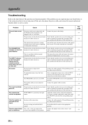
Problem A "humming" sound is low while playing a record. The remote control does not work or function properly. Cause Incorrect cable connections. Remedy Connect the audio cable plugs firmly. Incorrect setting for the MM/MC switch on the power of the turntable. The remote control functions within a maximum range of a piano cleaning cloth is striking the remote control sensor of this unit Polish finish on the side panels Use of 6 m (20 ft) and no more than 30...
Problem A "humming" sound is low while playing a record. The remote control does not work or function properly. Cause Incorrect cable connections. Remedy Connect the audio cable plugs firmly. Incorrect setting for the MM/MC switch on the power of the turntable. The remote control functions within a maximum range of a piano cleaning cloth is striking the remote control sensor of this unit Polish finish on the side panels Use of 6 m (20 ft) and no more than 30...


