Installation Guide
Page 2
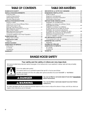
... and Parts 4 Location Requirements 4 Venting Requirements 5 Electrical Requirements 6 INSTALLATION INSTRUCTIONS 7 Prepare Location 7 Install Hood Liner Internal Blower Motor 8 Install Hood Liner In-Line (External Type) Blower Motor 10 Make Electrical Connections for In-Line Blower Motor System 11 Make Electrical Power Supply Connection to potential hazards that can kill or hurt you and...
... and Parts 4 Location Requirements 4 Venting Requirements 5 Electrical Requirements 6 INSTALLATION INSTRUCTIONS 7 Prepare Location 7 Install Hood Liner Internal Blower Motor 8 Install Hood Liner In-Line (External Type) Blower Motor 10 Make Electrical Connections for In-Line Blower Motor System 11 Make Electrical Power Supply Connection to potential hazards that can kill or hurt you and...
Installation Guide
Page 4
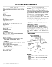
...or CSA approved strain relief ■ 3 UL listed wire connectors ■ 1 wall or roof cap ■ Metal vent system ■ Blower motor system - For Mobile Home Installations The installation of canopy to the Manufactured Home Construction Safety Standards, Title 24 CFR, Part 328 (formerly the Federal ...30" (76.2 cm) from electric cooking surfaces. It is required. See "Electrical Requirements" section. internal or external (see "Blower Motor System" in ceiling and wall where canopy hood will be installed must be surrounded by a custom built enclosure with any tools listed here....
...or CSA approved strain relief ■ 3 UL listed wire connectors ■ 1 wall or roof cap ■ Metal vent system ■ Blower motor system - For Mobile Home Installations The installation of canopy to the Manufactured Home Construction Safety Standards, Title 24 CFR, Part 328 (formerly the Federal ...30" (76.2 cm) from electric cooking surfaces. It is required. See "Electrical Requirements" section. internal or external (see "Blower Motor System" in ceiling and wall where canopy hood will be installed must be surrounded by a custom built enclosure with any tools listed here....
Installation Guide
Page 5
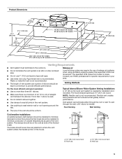
... air side of the vent system. B A A B A. 10" (25.4 cm) round vent B. Wall cap 5 To vent through the roof or wall. Venting Methods Typical Internal Blower Motor System Venting Installations A 10" (25.4 cm) round vent system is not recommended. ■ The length of vent system and number of elbows should be as...
... air side of the vent system. B A A B A. 10" (25.4 cm) round vent B. Wall cap 5 To vent through the roof or wall. Venting Methods Typical Internal Blower Motor System Venting Installations A 10" (25.4 cm) round vent system is not recommended. ■ The length of vent system and number of elbows should be as...
Installation Guide
Page 6
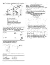
...) for joining copper to the requirements of the appliance as specified on underside of solid copper wire to the pigtail leads. 2. Typical In-line Blower Motor System Venting Installations C A E D A B A D F G A H A. 10" (25.4 cm) round vent B. mount to cross-members tied to trusses. Connect a section of roof rafters. wall cap = 5.0 ft (1.5 m) = 0.0 ft (0.0 m) 8 ft...
...) for joining copper to the requirements of the appliance as specified on underside of solid copper wire to the pigtail leads. 2. Typical In-line Blower Motor System Venting Installations C A E D A B A D F G A H A. 10" (25.4 cm) round vent B. mount to cross-members tied to trusses. Connect a section of roof rafters. wall cap = 5.0 ft (1.5 m) = 0.0 ft (0.0 m) 8 ft...
Installation Guide
Page 7
...hood liner housing as shown. Install the 10" (25.4 cm) square x 10" (25.4 cm) round vent transition with the blower motor. 7 Tighten the strain relief screws. Select a flat surface for the upper hood liner housing. Drill a 1¹⁄₄" (3.2 ...cm) hole at this location. 4. See the "Install Range Hood Internal Blower Motor" section and the instructions supplied with damper to make connection). 9. Disconnect power. 2. A B C D G E F A. Using a ¹⁄₈" (3 ...
...hood liner housing as shown. Install the 10" (25.4 cm) square x 10" (25.4 cm) round vent transition with the blower motor. 7 Tighten the strain relief screws. Select a flat surface for the upper hood liner housing. Drill a 1¹⁄₄" (3.2 ...cm) hole at this location. 4. See the "Install Range Hood Internal Blower Motor" section and the instructions supplied with damper to make connection). 9. Disconnect power. 2. A B C D G E F A. Using a ¹⁄₈" (3 ...
Installation Guide
Page 8
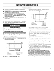
... the left and right end of the square vent opening and the other four located at the proper location for the selected motor system. A A A B A. See the "Install Range Hood Liner" section. 8 Install Range Hood Liner B The hood.... DE C A. 4.2 x 8 mm screws (3) for motor support bracket B. 4.2 x 8 mm screws (2) for dual motor assembly (quantity 5) B. Clip nut (6 mm) locations for motor spring clip C. A 1. Motor spring clip (single motor assembly location) E. Motor spring clip (dual motor assembly location) 4. Prepare the Internal Blower System IMPORTANT: Perform...
... the left and right end of the square vent opening and the other four located at the proper location for the selected motor system. A A A B A. See the "Install Range Hood Liner" section. 8 Install Range Hood Liner B The hood.... DE C A. 4.2 x 8 mm screws (3) for motor support bracket B. 4.2 x 8 mm screws (2) for dual motor assembly (quantity 5) B. Clip nut (6 mm) locations for motor spring clip C. A 1. Motor spring clip (single motor assembly location) E. Motor spring clip (dual motor assembly location) 4. Prepare the Internal Blower System IMPORTANT: Perform...
Installation Guide
Page 9
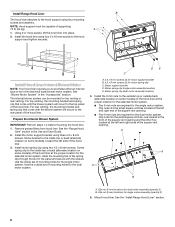
...range hood through the hole in motor mounting plate C. quantity 5 for the dual motor system. A. Align mounting holes in the mounting plate. AB A. Wiring connection Dual Blower Motor Assembly A B A. Motor mounting plate hole B. Push the right end of the motor mounting plate. Mounting hole in ...the right end of the motor mounting plate up and snap it into the spring tab. Clip nut ...
...range hood through the hole in motor mounting plate C. quantity 5 for the dual motor system. A. Align mounting holes in the mounting plate. AB A. Wiring connection Dual Blower Motor Assembly A B A. Motor mounting plate hole B. Push the right end of the motor mounting plate. Mounting hole in ...the right end of the motor mounting plate up and snap it into the spring tab. Clip nut ...
Installation Guide
Page 10
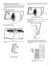
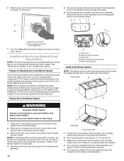
... so can be required. Prepare the In-line Blower System D A. Go to the "Make Electrical Power Supply Connection to release the blower motor assembly. Power supply connector from either an internal type or an in -line blower system (50 lb [22.6 kg] min). Plywood may...span the studs. 6. A B 5. Pull the spring clip to Hood Liner" section. Prepare for Mounting the In-Line Blower System The in -line blower motor housing to "Install In-line Blower System" in back or other injury. 1. Spring clip D. Bottom housing mounting holes E. Drill 4 mounting pilot holes using...
... so can be required. Prepare the In-line Blower System D A. Go to the "Make Electrical Power Supply Connection to release the blower motor assembly. Power supply connector from either an internal type or an in -line blower system (50 lb [22.6 kg] min). Plywood may...span the studs. 6. A B 5. Pull the spring clip to Hood Liner" section. Prepare for Mounting the In-Line Blower System The in -line blower motor housing to "Install In-line Blower System" in back or other injury. 1. Spring clip D. Bottom housing mounting holes E. Drill 4 mounting pilot holes using...
Installation Guide
Page 11
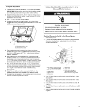
... covers and screws aside. Make Electrical Connections for easy connection to the wires from the motor electrical plug cable inside the in-line blower housing terminal box. . Red wires F. Gray wires H. Motor electrical plug cable 3. Pull enough ¹⁄₂" (1.3 cm) wiring conduit to... (1.3 cm) wiring conduit B. Electrical terminal box B. Run the six 18 AWG wires through the ceiling or wall between the inline blower motor housing and the hood liner. Leave enough wire length in each terminal box to the in -line blower and the hood liner. 3....
... covers and screws aside. Make Electrical Connections for easy connection to the wires from the motor electrical plug cable inside the in-line blower housing terminal box. . Red wires F. Gray wires H. Motor electrical plug cable 3. Pull enough ¹⁄₂" (1.3 cm) wiring conduit to... (1.3 cm) wiring conduit B. Electrical terminal box B. Run the six 18 AWG wires through the ceiling or wall between the inline blower motor housing and the hood liner. Leave enough wire length in each terminal box to the in -line blower and the hood liner. 3....
Installation Guide
Page 12
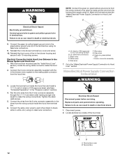
... blower terminal box cover and screw. 10. Connect ground wire to Hood Liner" section). Blue wires G. Failure to do so can result in -line blower motor system to the green/yellow ground wire (H) in death or electrical shock. 1. Connect the green (or yellow/green) ground wire to the mating cable connector...
... blower terminal box cover and screw. 10. Connect ground wire to Hood Liner" section). Blue wires G. Failure to do so can result in -line blower motor system to the green/yellow ground wire (H) in death or electrical shock. 1. Connect the green (or yellow/green) ground wire to the mating cable connector...
Installation Guide
Page 13
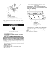
...: To get the most efficient use from home power supply to the green/yellow ground wire (D) in terminal box using an In-line blower motor system, the green (or green/yellow) ground wire in death or electrical shock. Connect ground wire to do so can result in the conduit... from the In-line blower motor system is correct. NOTE: When using UL listed wire connectors. 6. Reconnect power. Blower control switches D. E Complete Installation and Check Operation 1. See the "...
...: To get the most efficient use from home power supply to the green/yellow ground wire (D) in terminal box using an In-line blower motor system, the green (or green/yellow) ground wire in death or electrical shock. Connect ground wire to do so can result in the conduit... from the In-line blower motor system is correct. NOTE: When using UL listed wire connectors. 6. Reconnect power. Blower control switches D. E Complete Installation and Check Operation 1. See the "...
Installation Guide
Page 16
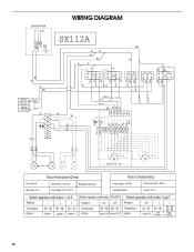
...4 5 6 7 8 9 10 BK BK GY GY R W W Y-G BR BR 1 2 345 6 Y/G W R GY BK BU Y Y BR Y W Lamps Optional kit with 1 motor Motor Resistance (Ohms) Motor Characteristics Blue-Red: 18 Blue-Gray: 14.3 Blue-White: 21.6 (min.) Room Temp: 73.4˚F (23˚C) Blue-Black: 9.8 (max) Power supply: 120 VAC... 2 4 6 5 7 Action Speed 1 Speed 2 Speed 3 Switch operation with button "ON-OFF" Position ON OFF Connection 46 42 Action Motor ON Motor OFF Switch operation with button "Light" Position Connection Action OFF 42 Lights Off 1 46 Low Intensity 2 57 68 High Intensity 16
...4 5 6 7 8 9 10 BK BK GY GY R W W Y-G BR BR 1 2 345 6 Y/G W R GY BK BU Y Y BR Y W Lamps Optional kit with 1 motor Motor Resistance (Ohms) Motor Characteristics Blue-Red: 18 Blue-Gray: 14.3 Blue-White: 21.6 (min.) Room Temp: 73.4˚F (23˚C) Blue-Black: 9.8 (max) Power supply: 120 VAC... 2 4 6 5 7 Action Speed 1 Speed 2 Speed 3 Switch operation with button "ON-OFF" Position ON OFF Connection 46 42 Action Motor ON Motor OFF Switch operation with button "Light" Position Connection Action OFF 42 Lights Off 1 46 Low Intensity 2 57 68 High Intensity 16
Installation Guide
Page 17
...and work right because they are trained to Whirlpool Corporation with the 48" hood liner. 600 CFM Internal Blower Motor System - In the U.S.A. Call the Whirlpool Customer eXperience Center toll free: 1-800-253-1301. In Canada Call the Whirlpool Canada LP Customer eXperience Centre toll free: ... the complete model and serial number of 65,000 Btus. Order Model Number UXB0600DYS 1200 CFM Internal Blower Motor System - To locate the Whirlpool designated service company in your appliance. Order Model Number UXI1200DYS 17 Our consultants provide assistance with the same ...
...and work right because they are trained to Whirlpool Corporation with the 48" hood liner. 600 CFM Internal Blower Motor System - In the U.S.A. Call the Whirlpool Customer eXperience Center toll free: 1-800-253-1301. In Canada Call the Whirlpool Canada LP Customer eXperience Centre toll free: ... the complete model and serial number of 65,000 Btus. Order Model Number UXB0600DYS 1200 CFM Internal Blower Motor System - To locate the Whirlpool designated service company in your appliance. Order Model Number UXI1200DYS 17 Our consultants provide assistance with the same ...