Installation Guide
Page 2
... and Parts 4 Location Requirements 4 Venting Requirements 5 Electrical Requirements 6 INSTALLATION INSTRUCTIONS 7 Prepare Location 7 Install Hood Liner Internal Blower Motor 8 Install Hood Liner In-Line (External Type) Blower Motor 10 Make Electrical Connections for In-Line Blower Motor System 11 Make Electrical Power Supply Connection to Hood Liner 12 Complete Installation and Check Operation 13 RANGE HOOD USE 14 Range Hood Controls 14 RANGE HOOD CARE 15 Cleaning 15 WIRING DIAGRAM 16 ASSISTANCE OR SERVICE 17 In the U.S.A 17 In Canada 17 Accessories 17 WARRANTY 18 TABLE...
... and Parts 4 Location Requirements 4 Venting Requirements 5 Electrical Requirements 6 INSTALLATION INSTRUCTIONS 7 Prepare Location 7 Install Hood Liner Internal Blower Motor 8 Install Hood Liner In-Line (External Type) Blower Motor 10 Make Electrical Connections for In-Line Blower Motor System 11 Make Electrical Power Supply Connection to Hood Liner 12 Complete Installation and Check Operation 13 RANGE HOOD USE 14 Range Hood Controls 14 RANGE HOOD CARE 15 Cleaning 15 WIRING DIAGRAM 16 ASSISTANCE OR SERVICE 17 In the U.S.A 17 In Canada 17 Accessories 17 WARRANTY 18 TABLE...
Installation Guide
Page 3
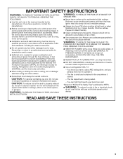
... accordance with all applicable codes and standards, including fire-rated construction. ■ Do not operate any fan with any solid-state speed control device. Grease should not be vented outdoors. BE CAREFUL TO PREVENT BURNS. The fire is being switched on fan or filter. ■ Use proper pan size. do not use cookware appropriate for proper combustion and exhausting of gases through the flue (chimney) of the surface...
... accordance with all applicable codes and standards, including fire-rated construction. ■ Do not operate any fan with any solid-state speed control device. Grease should not be vented outdoors. BE CAREFUL TO PREVENT BURNS. The fire is being switched on fan or filter. ■ Use proper pan size. do not use cookware appropriate for proper combustion and exhausting of gases through the flue (chimney) of the surface...
Installation Guide
Page 4
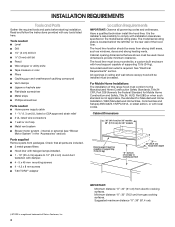
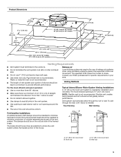
... Remove parts from gas cooking surfaces. The hood liner location should be surrounded by a custom built enclosure with installation clearances specified on the rear wall of Saturn Fasteners, Inc. 4 Cabinet opening dimensions that all governing codes and ordinances. Check that are included. ■ 3 metal grease filters ■ Hood liner with halogen lamps installed. ■ 1 - 10" (25.4 cm) square to cooking surface 22" (55.9 cm) Hood liner depth IMPORTANT: Minimum distance "X": 24" (61 cm) from strong draft...
... Remove parts from gas cooking surfaces. The hood liner location should be surrounded by a custom built enclosure with installation clearances specified on the rear wall of Saturn Fasteners, Inc. 4 Cabinet opening dimensions that all governing codes and ordinances. Check that are included. ■ 3 metal grease filters ■ Hood liner with halogen lamps installed. ■ 1 - 10" (25.4 cm) square to cooking surface 22" (55.9 cm) Hood liner depth IMPORTANT: Minimum distance "X": 24" (61 cm) from strong draft...
Installation Guide
Page 5
... Internal Blower Motor System Venting Installations A 10" (25.4 cm) round vent system is used. ■ Do not install 2 elbows together. ■ Use clamps to seal all joints in an attic or other enclosed area. ■ Do not use of makeup air systems when using ventilation systems greater than specified CFM of the thermal break. Roof cap A. 10" (25.4 cm) round vent B. Rigid metal vent is needed for specific requirements in your HVAC professional for installation...
... Internal Blower Motor System Venting Installations A 10" (25.4 cm) round vent system is used. ■ Do not install 2 elbows together. ■ Use clamps to seal all joints in an attic or other enclosed area. ■ Do not use of makeup air systems when using ventilation systems greater than specified CFM of the thermal break. Roof cap A. 10" (25.4 cm) round vent B. Rigid metal vent is needed for specific requirements in your HVAC professional for installation...
Installation Guide
Page 6
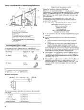
Duct horizontal; Vent Piece Equivalent Length 45° elbow 2.5 ft (0.8 m) 90° elbow 5.0 ft (1.5 m) Electrical Requirements Observe all local codes and ordinances. The model/serial plate is located behind the filter on the rear wall of the range hood. ■ Wire sizes must conform with the rating of the appliance as specified on the model/serial rating plate. Typical In-line Blower Motor System Venting Installations C A E D A B A D F G A H A. 10" (25.4 cm) round vent B. Mount on top of the National Electrical Code, ANSI/NFPA 70 (latest...
Duct horizontal; Vent Piece Equivalent Length 45° elbow 2.5 ft (0.8 m) 90° elbow 5.0 ft (1.5 m) Electrical Requirements Observe all local codes and ordinances. The model/serial plate is located behind the filter on the rear wall of the range hood. ■ Wire sizes must conform with the rating of the appliance as specified on the model/serial rating plate. Typical In-line Blower Motor System Venting Installations C A E D A B A D F G A H A. 10" (25.4 cm) round vent B. Mount on top of the National Electrical Code, ANSI/NFPA 70 (latest...
Installation Guide
Page 7
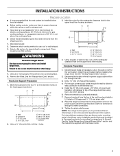
... wall for exhaust vent. ■ Hood liner is to be installed 24" (61.0 cm) minimum for electric cooking surfaces, 30" (76.2 cm) minimum for easy connection to use: roof or wall exhaust. 3. Determine the location where the power supply cable will be added to the range hood prior to mounting the range hood to top of the vent hood and install a UL listed or CSA approved ¹⁄₂" (1.3 cm) strain relief. 8. Remove terminal box cover and set...
... wall for exhaust vent. ■ Hood liner is to be installed 24" (61.0 cm) minimum for electric cooking surfaces, 30" (76.2 cm) minimum for easy connection to use: roof or wall exhaust. 3. Determine the location where the power supply cable will be added to the range hood prior to mounting the range hood to top of the vent hood and install a UL listed or CSA approved ¹⁄₂" (1.3 cm) strain relief. 8. Remove terminal box cover and set...
Installation Guide
Page 8
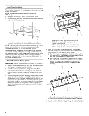
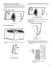
... the hood liner. Motor spring clip (dual motor assembly location) 4. Install Hood Liner Internal Blower Motor NOTE: Your hood liner requires you to the hood support using four 5 x 45 mm screws to the top panel of the hood liner. 3. Install Range Hood Liner B The hood liner attaches to purchase either an internal type or an in-line (external type) blower motor system. NOTE: Hood support must be mounted for motor spring clip C. A 1. Install the hood liner using four mounting screws and washers. See "Blower Motor System" in the Use and Care Guide. 2. For top venting...
... the hood liner. Motor spring clip (dual motor assembly location) 4. Install Hood Liner Internal Blower Motor NOTE: Your hood liner requires you to the hood support using four 5 x 45 mm screws to the top panel of the hood liner. 3. Install Range Hood Liner B The hood liner attaches to purchase either an internal type or an in-line (external type) blower motor system. NOTE: Hood support must be mounted for motor spring clip C. A 1. Install the hood liner using four mounting screws and washers. See "Blower Motor System" in the Use and Care Guide. 2. For top venting...
Installation Guide
Page 9
... be outside the slot in motor mounting plate C. quantity 5 for single motor; AB A. Screw with motor mounting clip nuts and install 6 x 16 mm screws and 6.4 mm lock washers (quantity 2 for dual motor). Install Hood Liner Internal Blower Motor 1. Wiring connection Dual Blower Motor Assembly A B A. Push the right end of the motor mounting plate. Slide the left for the single motor system and to the left mounting plate flange under the motor mounting bracket. Run the power supply wires and connector from the range hood through...
... be outside the slot in motor mounting plate C. quantity 5 for single motor; AB A. Screw with motor mounting clip nuts and install 6 x 16 mm screws and 6.4 mm lock washers (quantity 2 for dual motor). Install Hood Liner Internal Blower Motor 1. Wiring connection Dual Blower Motor Assembly A B A. Push the right end of the motor mounting plate. Slide the left for the single motor system and to the left mounting plate flange under the motor mounting bracket. Run the power supply wires and connector from the range hood through...
Installation Guide
Page 10
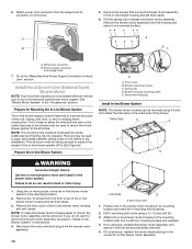
... ceiling joists or roof rafters to support the weight of the in -line (external type) blower motor system. This structure must be required. Spring clip D. Motor electrical plug Install In-line Blower System NOTE: The blower motor housing can be mounted using a 5 mm) drill bit. 3. If it is removed, reinstall the blower motor assembly and secure it on wiring box. Attach power cord connector from either an internal type or an in -line blower motor housing and set...
... ceiling joists or roof rafters to support the weight of the in -line (external type) blower motor system. This structure must be required. Spring clip D. Motor electrical plug Install In-line Blower System NOTE: The blower motor housing can be mounted using a 5 mm) drill bit. 3. If it is removed, reinstall the blower motor assembly and secure it on wiring box. Attach power cord connector from either an internal type or an in -line blower motor housing and set...
Installation Guide
Page 11
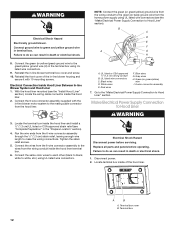
... 1. Locate the electrical terminal boxes in the in -line blower and the hood liner. 3. Replace all parts and panels before servicing. Disconnect power. 2. UL listed wire connectors C. Red wires F. Blue wires G. Green (or yellow/green) and green/yellow wires I A. Use UL listed wire connectors and connect the black wires (C) together. 4. Use UL listed wire connectors and connect the blue wires (F) together. 7. Make Electrical Connections for In-Line Blower Motor System WARNING Electrical Shock Hazard Disconnect power before operating. Connect the vent system to...
... 1. Locate the electrical terminal boxes in the in -line blower and the hood liner. 3. Replace all parts and panels before servicing. Disconnect power. 2. UL listed wire connectors C. Red wires F. Blue wires G. Green (or yellow/green) and green/yellow wires I A. Use UL listed wire connectors and connect the black wires (C) together. 4. Use UL listed wire connectors and connect the blue wires (F) together. 7. Make Electrical Connections for In-Line Blower Motor System WARNING Electrical Shock Hazard Disconnect power before operating. Connect the vent system to...
Installation Guide
Page 12
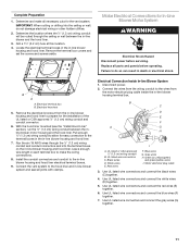
...or green/yellow) wire I A. Disconnect power. 2. UL listed wire connectors C. Locate the terminal box inside the hood liner terminal box. 6. A B A. Red wires F. Gray wires H. Run the wire ends from the hood liner. Electrical Shock Hazard Disconnect power before operating. I . 6-wire connector assembly 7. UL listed or CSA approved ¹⁄₂" (1.3 cm) wiring conduit B. Blue wires G. Failure to make the wiring connections. Tighten the strain relief screws. 5. Reinstall the front cover of the hood liner. Replace all parts and panels before servicing. Failure to...
...or green/yellow) wire I A. Disconnect power. 2. UL listed wire connectors C. Locate the terminal box inside the hood liner terminal box. 6. A B A. Red wires F. Gray wires H. Run the wire ends from the hood liner. Electrical Shock Hazard Disconnect power before operating. I . 6-wire connector assembly 7. UL listed or CSA approved ¹⁄₂" (1.3 cm) wiring conduit B. Blue wires G. Failure to make the wiring connections. Tighten the strain relief screws. 5. Reinstall the front cover of the hood liner. Replace all parts and panels before servicing. Failure to...
Installation Guide
Page 13
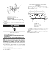
...new hood liner, read the "Range Hood Use" section. 13 Halogen lights B. Use UL listed wire connectors and connect white wires (A) together. Install terminal box cover. 7. Install grease filters. See the B "Range Hood Use" section. Reconnect power. Home power supply F. If the range hood does not operate, check to be connected with the green (or bare) wire of the range hood blower and lights. E Complete Installation and Check Operation 1. A 2. Check that the wiring is to see whether a circuit breaker has tripped or a household fuse has blown. Halogen light switch C.
...new hood liner, read the "Range Hood Use" section. 13 Halogen lights B. Use UL listed wire connectors and connect white wires (A) together. Install terminal box cover. 7. Install grease filters. See the B "Range Hood Use" section. Reconnect power. Home power supply F. If the range hood does not operate, check to be connected with the green (or bare) wire of the range hood blower and lights. E Complete Installation and Check Operation 1. A 2. Check that the wiring is to see whether a circuit breaker has tripped or a household fuse has blown. Halogen light switch C.
Installation Guide
Page 14
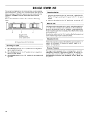
... turn on the underside of the range hood. The fan will turn the fan to operate several minutes after the cooking is not active and the range hood functions normally. Move the fan speed switch to restart the range hood. 14 For best results, start the hood before cooking and allow it to high speed when necessary. The hood controls are located on the fan when excessive heat is designed to turn range hood light OFF. When the fan switch...
... turn on the underside of the range hood. The fan will turn the fan to operate several minutes after the cooking is not active and the range hood functions normally. Move the fan speed switch to restart the range hood. 14 For best results, start the hood before cooking and allow it to high speed when necessary. The hood controls are located on the fan when excessive heat is designed to turn range hood light OFF. When the fan switch...
Installation Guide
Page 15
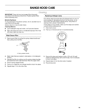
... filter. Remove the lamp and replace it into upper track. 4. Turn it counterclockwise. Replacing a Halogen Lamp Turn off the range hood and allow the halogen lamp to lock it with a 120-volt, 50-watt maximum halogen lamp with a GU10 base. Push in dishwasher or hot detergent solution. 3. Always wipe dry to the following instructions. Replace grease filters before calling service. 1. Metal Grease Filter: 1. Wash metal filters as needed . 5. Repeat steps 1-5 for the other filter. 3. RANGE HOOD CARE Cleaning IMPORTANT: Clean...
... filter. Remove the lamp and replace it into upper track. 4. Turn it counterclockwise. Replacing a Halogen Lamp Turn off the range hood and allow the halogen lamp to lock it with a 120-volt, 50-watt maximum halogen lamp with a GU10 base. Push in dishwasher or hot detergent solution. 3. Always wipe dry to the following instructions. Replace grease filters before calling service. 1. Metal Grease Filter: 1. Wash metal filters as needed . 5. Repeat steps 1-5 for the other filter. 3. RANGE HOOD CARE Cleaning IMPORTANT: Clean...
Installation Guide
Page 16
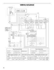
... Y W Lamps Optional kit with 1 motor Motor Resistance (Ohms) Motor Characteristics Blue-Red: 18 Blue-Gray: 14.3 Blue-White: 21.6 (min.) Room Temp: 73.4˚F (23˚C) Blue-Black: 9.8 (max) Power supply: 120 VAC Frequency: 60 Hz Power absorption: 420 W Current: 3.7A Switch operation with button "1-2-3" Position 1 2 3 Connection 4 2 4 6 5 7 Action Speed 1 Speed 2 Speed 3 Switch operation with button "ON-OFF" Position ON OFF Connection 46 42 Action Motor ON Motor OFF Switch operation with button "Light" Position Connection...
... Y W Lamps Optional kit with 1 motor Motor Resistance (Ohms) Motor Characteristics Blue-Red: 18 Blue-Gray: 14.3 Blue-White: 21.6 (min.) Room Temp: 73.4˚F (23˚C) Blue-Black: 9.8 (max) Power supply: 120 VAC Frequency: 60 Hz Power absorption: 420 W Current: 3.7A Switch operation with button "1-2-3" Position 1 2 3 Connection 4 2 4 6 5 7 Action Speed 1 Speed 2 Speed 3 Switch operation with button "ON-OFF" Position ON OFF Connection 46 42 Action Motor ON Motor OFF Switch operation with button "Light" Position Connection...
Installation Guide
Page 17
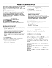
... Stainless Steel Grease Filter - Order Model Number UXB1200DYS 600 CFM In-Line Blower Motor System - Whirlpool designated service technicians are trained to Whirlpool Corporation with : ■ Features and specifications on our full line of appliances. ■ Use and maintenance procedures. ■ Accessory and repair parts sales. ■ Referrals to local dealers, repair parts distributors and service companies. Order Model Number UXB0600DYS 1200 CFM Internal Blower Motor System - Order Model Number UXI1200DYS 17 In the U.S.A. To locate the Whirlpool designated service...
... Stainless Steel Grease Filter - Order Model Number UXB1200DYS 600 CFM In-Line Blower Motor System - Whirlpool designated service technicians are trained to Whirlpool Corporation with : ■ Features and specifications on our full line of appliances. ■ Use and maintenance procedures. ■ Accessory and repair parts sales. ■ Referrals to local dealers, repair parts distributors and service companies. Order Model Number UXB0600DYS 1200 CFM Internal Blower Motor System - Order Model Number UXI1200DYS 17 In the U.S.A. To locate the Whirlpool designated service...
Installation Guide
Page 18
... limited warranty does not apply. This limited warranty is valid only in the United States or Canada and applies only when the major appliance is contrary to the appliance. 9. Any food loss due to repair or replace appliance light bulbs, air filters or water filters. Costs associated with the removal from unauthorized modifications made to published user or operator instructions and/or installation instructions. 4. DISCLAIMER OF IMPLIED WARRANTIES; Outside the 50 United...
... limited warranty does not apply. This limited warranty is valid only in the United States or Canada and applies only when the major appliance is contrary to the appliance. 9. Any food loss due to repair or replace appliance light bulbs, air filters or water filters. Costs associated with the removal from unauthorized modifications made to published user or operator instructions and/or installation instructions. 4. DISCLAIMER OF IMPLIED WARRANTIES; Outside the 50 United...
Dimension Guide
Page 1
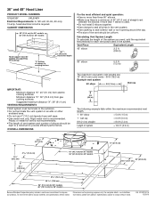
... canopy to improve Dimensions are : 10" (25.4 cm) round vents - 60 ft (18.3 m) Example vent system 90 elbow 6 ft (1.8 m) Wall cap 2 ft (0.6 m) The following example falls within the maximum recommended vent length. 1 - 90° elbow = 5.0 ft (1.5 m) 1 - Ref. 36" and 48" Hood Liner PRODUCT MODEL NUMBERS UXL6036Y UXL6048Y Electrical Requirements: A 120-volt, 60-Hz, AC-only, 15-amp, fused electrical circuit is used in the system. q Use clamps to seal exterior wall or roof opening around the cap. q Use...
... canopy to improve Dimensions are : 10" (25.4 cm) round vents - 60 ft (18.3 m) Example vent system 90 elbow 6 ft (1.8 m) Wall cap 2 ft (0.6 m) The following example falls within the maximum recommended vent length. 1 - 90° elbow = 5.0 ft (1.5 m) 1 - Ref. 36" and 48" Hood Liner PRODUCT MODEL NUMBERS UXL6036Y UXL6048Y Electrical Requirements: A 120-volt, 60-Hz, AC-only, 15-amp, fused electrical circuit is used in the system. q Use clamps to seal exterior wall or roof opening around the cap. q Use...

Warranty Information
Page 1
... WARRANTY LIMITED WARRANTY For one year from the date of consumables or cleaning products not approved by Whirlpool. 5. Service must provide proof of the Use & Care Guide. Service calls to the finish of your authorized Whirlpool dealer to refrigerator or freezer product failures. 7. Outside the 50 United States and Canada, this information on the model and serial number label located on how to published user or operator instructions and/or installation instructions...
... WARRANTY LIMITED WARRANTY For one year from the date of consumables or cleaning products not approved by Whirlpool. 5. Service must provide proof of the Use & Care Guide. Service calls to the finish of your authorized Whirlpool dealer to refrigerator or freezer product failures. 7. Outside the 50 United States and Canada, this information on the model and serial number label located on how to published user or operator instructions and/or installation instructions...


