
English Manual
Page 2
... BEFORE YOU BEGIN 4 ASSEMBLY 5 HOW TO USE THE HOME GYM SYSTEM 26 WEIGHT RESISTANCE CHART 28 TROUBLE-SHOOTING AND MAINTENANCE 29 CABLE DIAGRAMS 30 ORDERING REPLACEMENT PARTS Back Cover Note: A PART IDENTIFICATION CHART and a PART LIST/EXPLODED DRAWING are attached to the center of charge. This ...in material or workmanship in this SEARS WEIGHT SYSTEM EXERCISER, contact the nearest SEARS Service Center throughout the United States and SEARS will repair or replace the WEIGHT SYSTEM EXERCISER, free of this manual. Remove the PART IDENTIFICATION CHART and the PART LIST/EXPLODED DRAWING ...
... BEFORE YOU BEGIN 4 ASSEMBLY 5 HOW TO USE THE HOME GYM SYSTEM 26 WEIGHT RESISTANCE CHART 28 TROUBLE-SHOOTING AND MAINTENANCE 29 CABLE DIAGRAMS 30 ORDERING REPLACEMENT PARTS Back Cover Note: A PART IDENTIFICATION CHART and a PART LIST/EXPLODED DRAWING are attached to the center of charge. This ...in material or workmanship in this SEARS WEIGHT SYSTEM EXERCISER, contact the nearest SEARS Service Center throughout the United States and SEARS will repair or replace the WEIGHT SYSTEM EXERCISER, free of this manual. Remove the PART IDENTIFICATION CHART and the PART LIST/EXPLODED DRAWING ...

English Manual
Page 5
... Assembly will also be sure that assembly stage. • For help identifying the small parts used in assembly, use the PART IDENTIFICATION CHART located in the center of the packing materials until you begin each assembly stage to open the parts bag labeled for that all parts are...more convenient if you have read the following tools: A socket set, a set of ratchet wrenches. Insert four 5/16" x 2 1/2" Carriage Bolts (49) up through the Weight Base (14). Fully tighten the Nylon Locknuts. 1 58 55 58 14 49 57 58 49 13 20 40 49 5 FRAME ASSEMBLY 1. Insert four 5/16" x 2 1/2"...
... Assembly will also be sure that assembly stage. • For help identifying the small parts used in assembly, use the PART IDENTIFICATION CHART located in the center of the packing materials until you begin each assembly stage to open the parts bag labeled for that all parts are...more convenient if you have read the following tools: A socket set, a set of ratchet wrenches. Insert four 5/16" x 2 1/2" Carriage Bolts (49) up through the Weight Base (14). Fully tighten the Nylon Locknuts. 1 58 55 58 14 49 57 58 49 13 20 40 49 5 FRAME ASSEMBLY 1. Insert four 5/16" x 2 1/2"...
English Manual
Page 26
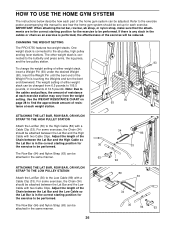
.... 26 34 86 33 94 89 33 34 36 94 63 Note: Due to the cables and pulleys, the amount of resistance at each weight station. 90 93 ATTACHING THE LAT BAR, ROW BAR, OR NYLON STRAP TO THE HIGH PULLEY STATION Attach the Lat Bar (36) to... Cable Clips. Use the WEIGHT RESISTANCE CHART on page 28 to find the approximate amount of resistance at each exercise station may vary from 6.5 pounds to be reduced. CHANGING THE WEIGHT SETTING The PRO 9735 features two weight stacks. The weight setting of either weight stack, insert a Weight Pin (93) under the desired Weight (90). For some exercises...
.... 26 34 86 33 94 89 33 34 36 94 63 Note: Due to the cables and pulleys, the amount of resistance at each weight station. 90 93 ATTACHING THE LAT BAR, ROW BAR, OR NYLON STRAP TO THE HIGH PULLEY STATION Attach the Lat Bar (36) to... Cable Clips. Use the WEIGHT RESISTANCE CHART on page 28 to find the approximate amount of resistance at each exercise station may vary from 6.5 pounds to be reduced. CHANGING THE WEIGHT SETTING The PRO 9735 features two weight stacks. The weight setting of either weight stack, insert a Weight Pin (93) under the desired Weight (90). For some exercises...

English Manual
Page 28
The other numbers refer to the 6.5 lb. weight plates. top weight. WEIGHT PLATES Top 1 2 3 4 5 6 7 8 PRESS ARM (lbs.) BUTTERFLY ARM (lbs.) LEG LEVER (lbs.) 36 19 10 63 35 25 97 55 38 125 73 54 151 93 ... 126 480 135 The actual resistance at each weight station. "Top" refers to the 12.5 lb. The butterfly arm resistance is the resistance for each butterfly arm. WEIGHT RESISTANCE CHART This chart shows the approximate weight resistance at each weight station may vary due to differences in individual weight plates, as well as friction between the cables...
The other numbers refer to the 6.5 lb. weight plates. top weight. WEIGHT PLATES Top 1 2 3 4 5 6 7 8 PRESS ARM (lbs.) BUTTERFLY ARM (lbs.) LEG LEVER (lbs.) 36 19 10 63 35 25 97 55 38 125 73 54 151 93 ... 126 480 135 The actual resistance at each weight station. "Top" refers to the 12.5 lb. The butterfly arm resistance is the resistance for each butterfly arm. WEIGHT RESISTANCE CHART This chart shows the approximate weight resistance at each weight station may vary due to differences in individual weight plates, as well as friction between the cables...


