
English Manual
Page 2
Remove the PART IDENTIFICATION CHART and the PART LIST/EXPLODED DRAWING before beginning assembly. WEIDER is a registered trademark of this manual. TABLE OF CONTENTS IMPORTANT PRECAUTIONS 3 BEFORE YOU BEGIN 4 ASSEMBLY 5 ADJUSTMENTS 21 WEIGHT RESISTANCE CHART 23 TROUBLE-SHOOTING AND MAINTENANCE 24 CABLE DIAGRAMS 25 ORDERING REPLACEMENT PARTS Back Cover LIMITED WARRANTY Back Cover Note: A PART IDENTIFICATION CHART and a PART LIST/EXPLODED DRAWING are attached at the center of ICON Health & Fitness, Inc. 2
Remove the PART IDENTIFICATION CHART and the PART LIST/EXPLODED DRAWING before beginning assembly. WEIDER is a registered trademark of this manual. TABLE OF CONTENTS IMPORTANT PRECAUTIONS 3 BEFORE YOU BEGIN 4 ASSEMBLY 5 ADJUSTMENTS 21 WEIGHT RESISTANCE CHART 23 TROUBLE-SHOOTING AND MAINTENANCE 24 CABLE DIAGRAMS 25 ORDERING REPLACEMENT PARTS Back Cover LIMITED WARRANTY Back Cover Note: A PART IDENTIFICATION CHART and a PART LIST/EXPLODED DRAWING are attached at the center of ICON Health & Fitness, Inc. 2
English Manual
Page 4
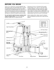
...a selection of weight stations designed to the weight system (see the front cover of the body. If you for selecting the versatile WEIDER® PRO 9400 weight system. Length: 64 in . BEFORE YOU BEGIN Thank you have additional questions, please call our Customer Service Before reading further,... group of this manual carefully before calling. Lat Bar High Pulley Station Warning Decal No. 1 Butterfly Arms Press Arm Warning Decal No. 3 ASSEMBLED DIMENSIONS: Height: 76 in . Ab Pulley Station Warning Decal No. 1 Military Press Arm Backrests Leg Lever Leg Press Plate Low Pulley Station ...
...a selection of weight stations designed to the weight system (see the front cover of the body. If you for selecting the versatile WEIDER® PRO 9400 weight system. Length: 64 in . BEFORE YOU BEGIN Thank you have additional questions, please call our Customer Service Before reading further,... group of this manual carefully before calling. Lat Bar High Pulley Station Warning Decal No. 1 Butterfly Arms Press Arm Warning Decal No. 3 ASSEMBLED DIMENSIONS: Height: 76 in . Ab Pulley Station Warning Decal No. 1 Military Press Arm Backrests Leg Lever Leg Press Plate Low Pulley Station ...
English Manual
Page 5
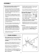
... Carriage Bolts up through the Stabilizer (5). You may have been preattached for that all parts as shown in the drawings. until assembly is completed. • Assembly is divided into the end of the weight system in a cleared area and remove the packing materials; Press a 2" Square ...screwdriver • One (1) rubber mallet • Lubricant, such as grease or petroleum jelly, and soapy water will also be needed. • Assembly will go smoothly. Press two 2" Square Outer Caps (51) onto the indicated locations on the Stabilizer (5). Mountain Time. If a part is ...
... Carriage Bolts up through the Stabilizer (5). You may have been preattached for that all parts as shown in the drawings. until assembly is completed. • Assembly is divided into the end of the weight system in a cleared area and remove the packing materials; Press a 2" Square ...screwdriver • One (1) rubber mallet • Lubricant, such as grease or petroleum jelly, and soapy water will also be needed. • Assembly will go smoothly. Press two 2" Square Outer Caps (51) onto the indicated locations on the Stabilizer (5). Mountain Time. If a part is ...
English Manual
Page 9
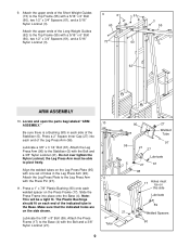
...Plate (95) with a 5/16" x 6" Bolt (60), two 1/2" x 3/4" Spacers (61), and a 5/16" Nylon Locknut (3). Locate and open the parts bag labeled "ARM ASSEMBLY." Lubricate a 3/8" x 3 1/4" Bolt (67). Make sure that the indicated holes are on the Press Frame (17). 9. Attach the upper ends of the Long Weight Guides (62... Press Arm with a 5/16" x 6" Bolt (60), two 1/2" x 3/4" Spacers (61), and a 5/16" Nylon Locknut (3). 9 61 60 73 3 61 60 3 55 62 ARM ASSEMBLY 10. Attach the Leg Press Plate to the Top Frame (55) with the Press Pin (97). 11. Slide the Press Frame into each welded spacer...
...Plate (95) with a 5/16" x 6" Bolt (60), two 1/2" x 3/4" Spacers (61), and a 5/16" Nylon Locknut (3). Locate and open the parts bag labeled "ARM ASSEMBLY." Lubricate a 3/8" x 3 1/4" Bolt (67). Make sure that the indicated holes are on the Press Frame (17). 9. Attach the upper ends of the Long Weight Guides (62... Press Arm with a 5/16" x 6" Bolt (60), two 1/2" x 3/4" Spacers (61), and a 5/16" Nylon Locknut (3). 9 61 60 73 3 61 60 3 55 62 ARM ASSEMBLY 10. Attach the Leg Press Plate to the Top Frame (55) with the Press Pin (97). 11. Slide the Press Frame into each welded spacer...

English Manual
Page 10
... 21 Attach a "V"-Pulley (50) and a Long Cable Trap (31) to the Right Arm (48) with two 5/16" x 2 1/2" Bolts (22) and two 5/16" Nylon Locknuts (3). 22 Assemble the other Press Arm (46) in the same manner. 46 3 17 13. Arm identification is behind the indicated bracket on the Retainers bend toward the...
... 21 Attach a "V"-Pulley (50) and a Long Cable Trap (31) to the Right Arm (48) with two 5/16" x 2 1/2" Bolts (22) and two 5/16" Nylon Locknuts (3). 22 Assemble the other Press Arm (46) in the same manner. 46 3 17 13. Arm identification is behind the indicated bracket on the Retainers bend toward the...
English Manual
Page 11
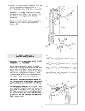
...Top Frame (55) with a 3/8" x 3 1/4" Bolt (67) and a 3/8" Nylon Locknut (21). 74 32 49 32 84 80 67 56 33 80 CABLE ASSEMBLY 16 16. Identify the four Cables by comparing the lengths and ends of this section, fully unwind the four Cables. the pulleys must be able... with a 3/8" x 3 3/4" Bolt (88) and a 3/8" Nylon Locknut (21). See the inset drawing. Locate and open the parts bags labeled "CABLE ASSEMBLY" and "PULLEYS." IMPORTANT: While assembling the cables, do not over tighten the bolts and nuts attaching the 17 pulleys; The approximate length of the Military Press Arm (84...
...Top Frame (55) with a 3/8" x 3 1/4" Bolt (67) and a 3/8" Nylon Locknut (21). 74 32 49 32 84 80 67 56 33 80 CABLE ASSEMBLY 16 16. Identify the four Cables by comparing the lengths and ends of this section, fully unwind the four Cables. the pulleys must be able... with a 3/8" x 3 3/4" Bolt (88) and a 3/8" Nylon Locknut (21). See the inset drawing. Locate and open the parts bags labeled "CABLE ASSEMBLY" and "PULLEYS." IMPORTANT: While assembling the cables, do not over tighten the bolts and nuts attaching the 17 pulleys; The approximate length of the Military Press Arm (84...
English Manual
Page 13
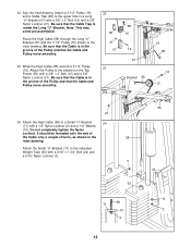
... sure that the Cable and Pulley move smoothly. 58 15 12 57 Bracket 58 15 58 12 15 21 24. Note: This may come pre-assembled. Attach the High Cable (58) to the upper hole in a Long "U"-Bracket (57) with a 1/4" Nylon Locknut (2) and a 1/4" Washer (10). See the inset drawing. Route the...
... sure that the Cable and Pulley move smoothly. 58 15 12 57 Bracket 58 15 58 12 15 21 24. Note: This may come pre-assembled. Attach the High Cable (58) to the upper hole in a Long "U"-Bracket (57) with a 1/4" Nylon Locknut (2) and a 1/4" Washer (10). See the inset drawing. Route the...
English Manual
Page 18
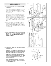
... the Front Backrest (41) to the Leg Press Backrest (85) with a 1/4" x 2 1/2" Screw (43) and a 1/4" Washer (10). 38. Locate and open the parts bag labeled "SEAT ASSEMBLY." Insert the 1/4" x 2" Carriage Bolt (38) through the center hole in the Front Seat Frame (36). Attach one end of the Seat to the Leg Press... the Leg Press Seat Frame with a 1/4" Washer (10) onto the Carriage Bolt. Insert a 1/4" x 2 1/2" Carriage Bolt (92) through the indicated hole in a Seat Plate (37). SEAT ASSEMBLY 37.
... the Front Backrest (41) to the Leg Press Backrest (85) with a 1/4" x 2 1/2" Screw (43) and a 1/4" Washer (10). 38. Locate and open the parts bag labeled "SEAT ASSEMBLY." Insert the 1/4" x 2" Carriage Bolt (38) through the center hole in the Front Seat Frame (36). Attach one end of the Seat to the Leg Press... the Leg Press Seat Frame with a 1/4" Washer (10) onto the Carriage Bolt. Insert a 1/4" x 2 1/2" Carriage Bolt (92) through the indicated hole in a Seat Plate (37). SEAT ASSEMBLY 37.
English Manual
Page 25
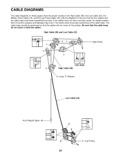
... four cables and the cable traps have not been correctly routed, the weight system will not come off the pulleys. If the cables have been assembled correctly. High Cable (58) and Low Cable (23) 7 5 23 4 1-High Pulley TOP VIEW 6 High Cable (58) 5-Long "U"-Bracket Low Cable (23) Front Weight Stack-8 4 3 2 1-Low...
... four cables and the cable traps have not been correctly routed, the weight system will not come off the pulleys. If the cables have been assembled correctly. High Cable (58) and Low Cable (23) 7 5 23 4 1-High Pulley TOP VIEW 6 High Cable (58) 5-Long "U"-Bracket Low Cable (23) Front Weight Stack-8 4 3 2 1-Low...


