
English Manual
Page 1
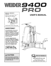
... CALL DIRECT TO OUR TOLL-FREE CUSTOMER HOT LINE. Write the serial number in this manual before using this manual for reference. Save this equipment. WESY39311 Serial No. The trained technicians on our customer hot line will guarantee complete satisfaction through assistance from our factory. MST CAUTION Read all precautions and instructions in the space above for future reference. USER'S MANUAL Visit our...
... CALL DIRECT TO OUR TOLL-FREE CUSTOMER HOT LINE. Write the serial number in this manual before using this manual for reference. Save this equipment. WESY39311 Serial No. The trained technicians on our customer hot line will guarantee complete satisfaction through assistance from our factory. MST CAUTION Read all precautions and instructions in the space above for future reference. USER'S MANUAL Visit our...
English Manual
Page 2
WEIDER is a registered trademark of this manual. TABLE OF CONTENTS IMPORTANT PRECAUTIONS 3 BEFORE YOU BEGIN 4 ASSEMBLY 5 ADJUSTMENTS 21 WEIGHT RESISTANCE CHART 23 TROUBLE-SHOOTING AND MAINTENANCE 24 CABLE DIAGRAMS 25 ORDERING REPLACEMENT PARTS Back Cover LIMITED WARRANTY Back Cover Note: A PART IDENTIFICATION CHART and a PART LIST/EXPLODED DRAWING are attached at the center of ICON Health & Fitness, Inc. 2 Remove the PART IDENTIFICATION CHART and the PART LIST/EXPLODED DRAWING before beginning assembly.
WEIDER is a registered trademark of this manual. TABLE OF CONTENTS IMPORTANT PRECAUTIONS 3 BEFORE YOU BEGIN 4 ASSEMBLY 5 ADJUSTMENTS 21 WEIGHT RESISTANCE CHART 23 TROUBLE-SHOOTING AND MAINTENANCE 24 CABLE DIAGRAMS 25 ORDERING REPLACEMENT PARTS Back Cover LIMITED WARRANTY Back Cover Note: A PART IDENTIFICATION CHART and a PART LIST/EXPLODED DRAWING are attached at the center of ICON Health & Fitness, Inc. 2 Remove the PART IDENTIFICATION CHART and the PART LIST/EXPLODED DRAWING before beginning assembly.
English Manual
Page 3
... of the owner to support a maximum user weight of serious injury, read the following important precautions before using the weight system. 1. The weight system is not legible, please call our Customer Service Department toll-free at all instructions in this manual. 2. Mountain Time, to protect the floor. 5. Never release the press arm, butterfly arms, military press arm, leg lever, leg press plate, lat bar or nylon strap while weights are properly tightened each time...
... of the owner to support a maximum user weight of serious injury, read the following important precautions before using the weight system. 1. The weight system is not legible, please call our Customer Service Department toll-free at all instructions in this manual. 2. Mountain Time, to protect the floor. 5. Never release the press arm, butterfly arms, military press arm, leg lever, leg press plate, lat bar or nylon strap while weights are properly tightened each time...
English Manual
Page 4
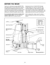
... in . Mountain Time (excluding holidays). Lat Bar High Pulley Station Warning Decal No. 1 Butterfly Arms Press Arm Warning Decal No. 3 ASSEMBLED DIMENSIONS: Height: 76 in . The serial number can be found on a decal attached to tone your body, build dramatic muscle size and strength, or improve your benefit, read this manual). Whether your goal is WESY39311. Department toll-free at 1-800-999-3756, Monday through...
... in . Mountain Time (excluding holidays). Lat Bar High Pulley Station Warning Decal No. 1 Butterfly Arms Press Arm Warning Decal No. 3 ASSEMBLED DIMENSIONS: Height: 76 in . The serial number can be found on a decal attached to tone your body, build dramatic muscle size and strength, or improve your benefit, read this manual). Whether your goal is WESY39311. Department toll-free at 1-800-999-3756, Monday through...
English Manual
Page 5
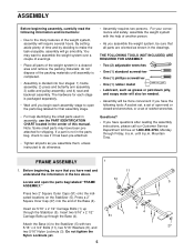
... indicated locations on the Stabilizer (5). Press a 2" Square Inner Cap (27) into four stages: 1) frame assembly, 2) press and butterfly arm assembly, 3) cable and pulley assembly, and 4) seat and backrest assembly. Insert six 5/16" x 2 1/2" Carriage Bolts (1) up through the Base (4). THE FOLLOWING TOOLS (NOT INCLUDED) ARE REQUIRED FOR ASSEMBLY: • Two (2) adjustable wrenches • One (1) standard screwdriver • One (1) phillips screwdriver • One (1) rubber mallet • Lubricant...
... indicated locations on the Stabilizer (5). Press a 2" Square Inner Cap (27) into four stages: 1) frame assembly, 2) press and butterfly arm assembly, 3) cable and pulley assembly, and 4) seat and backrest assembly. Insert six 5/16" x 2 1/2" Carriage Bolts (1) up through the Base (4). THE FOLLOWING TOOLS (NOT INCLUDED) ARE REQUIRED FOR ASSEMBLY: • Two (2) adjustable wrenches • One (1) standard screwdriver • One (1) phillips screwdriver • One (1) rubber mallet • Lubricant...
English Manual
Page 6
Slide the Rear Upright (74) and the Leg Press Upright (56) onto the indicated 5/16" x 2 1/2" Carriage Bolts (1) in the Base (4). Attach the Rubber Bumper (91) to the Leg Press Upright (56) with the #8 x 1/2" Self-tapping Screw (87). 2 27 87 91 74 3 3 1 3. Slide the Front Upright (42) onto the 5/16" x 2 1/2" Carriage Bolts (1) in the Stabilizer (5). Press a 2" Square Inner Cap into the Leg Press Upright (56). Hand tighten a 3 5/16" Nylon Locknut...
Slide the Rear Upright (74) and the Leg Press Upright (56) onto the indicated 5/16" x 2 1/2" Carriage Bolts (1) in the Base (4). Attach the Rubber Bumper (91) to the Leg Press Upright (56) with the #8 x 1/2" Self-tapping Screw (87). 2 27 87 91 74 3 3 1 3. Slide the Front Upright (42) onto the 5/16" x 2 1/2" Carriage Bolts (1) in the Stabilizer (5). Press a 2" Square Inner Cap into the Leg Press Upright (56). Hand tighten a 3 5/16" Nylon Locknut...
English Manual
Page 7
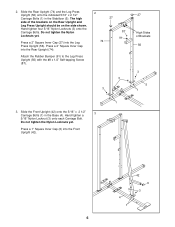
... Leg Press Seat Frame (79) onto the indicated 5/16" x 2 1/2" Carriage Bolts (1) in steps 1-5. 5 56 8 3 1 79 11 3 3 1 82 5 6. Be sure that the pin grooves are on the Top Frame. Attach the other end of Weights. Press a 1 3/4" Square Inner Cap (44) into each end of the crossbar. 27 Attach the Top Frame (55) to the Rear Upright (74) and the Leg Press Upright (56) with two 5/16" x 2 3/4" Bolts...
... Leg Press Seat Frame (79) onto the indicated 5/16" x 2 1/2" Carriage Bolts (1) in steps 1-5. 5 56 8 3 1 79 11 3 3 1 82 5 6. Be sure that the pin grooves are on the Top Frame. Attach the other end of Weights. Press a 1 3/4" Square Inner Cap (44) into each end of the crossbar. 27 Attach the Top Frame (55) to the Rear Upright (74) and the Leg Press Upright (56) with two 5/16" x 2 3/4" Bolts...
English Manual
Page 9
... open the parts bag labeled "ARM ASSEMBLY." Attach the Leg Press Arm (96) to the Base (4) with the Bolt and a 3/8" Nylon Locknut (21). Attach the Leg Press Plate to pivot freely. Note: This will be able to the Leg Press Arm with a 5/16" x 6" Bolt (60), two 1/2" x 3/4" Spacers (61), and a 5/16" Nylon Locknut (3). Attach the upper ends of the Long Weight Guides (62) to the Top Frame (55) with the Press Pin...
... open the parts bag labeled "ARM ASSEMBLY." Attach the Leg Press Arm (96) to the Base (4) with the Bolt and a 3/8" Nylon Locknut (21). Attach the Leg Press Plate to pivot freely. Note: This will be able to the Leg Press Arm with a 5/16" x 6" Bolt (60), two 1/2" x 3/4" Spacers (61), and a 5/16" Nylon Locknut (3). Attach the upper ends of the Long Weight Guides (62) to the Top Frame (55) with the Press Pin...

English Manual
Page 10
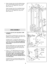
... (49) into the lower ends of the Right Arm is very important for step 14. Attach a "V"-Pulley (50) and a Long Cable Trap (31) to confuse the Right Arm with a 3/8" x 2 1/2" Bolt (86) and a 3/8" Nylon Locknut (21). Press a 1 3/4" Square Inner Cap (44) into the Press Arm. 44 49 Attach the Press Arm (46) to identify the Right Arm. Wet the lower end of the Press 46 Frame (17) with...
... (49) into the lower ends of the Right Arm is very important for step 14. Attach a "V"-Pulley (50) and a Long Cable Trap (31) to confuse the Right Arm with a 3/8" x 2 1/2" Bolt (86) and a 3/8" Nylon Locknut (21). Press a 1 3/4" Square Inner Cap (44) into the Press Arm. 44 49 Attach the Press Arm (46) to identify the Right Arm. Wet the lower end of the Press 46 Frame (17) with...
English Manual
Page 11
... Inner Caps (32) into the Military Press Arm. 21 Attach the Pivot Arm (80) to verify proper cable routing. Before beginning this manual to the Rear Upright (74) with two 5/16" x 2 1/4" Bolts (33) and two 5/16" Nylon Locknuts (3). IMPORTANT: While assembling the cables, do not over tighten the bolts and nuts attaching the 17 pulleys; Attach the Pulley to the Pivot Arm (80) with a 3/8" x 3 1/4" Bolt (67) and a 3/8" Nylon Locknut (21...
... Inner Caps (32) into the Military Press Arm. 21 Attach the Pivot Arm (80) to verify proper cable routing. Before beginning this manual to the Rear Upright (74) with two 5/16" x 2 1/4" Bolts (33) and two 5/16" Nylon Locknuts (3). IMPORTANT: While assembling the cables, do not over tighten the bolts and nuts attaching the 17 pulleys; Attach the Pulley to the Pivot Arm (80) with a 3/8" x 3 1/4" Bolt (67) and a 3/8" Nylon Locknut (21...

English Manual
Page 17
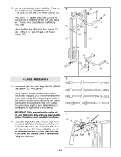
... the Leg Press Upright (56) with a 3/8" x 2" Bolt (12) and a 3/8" Nylon Locknut (21). Thread another 5/16" Nylon Jamnut onto the Bolt. Do not fully tighten the second Jamnut; It should be on the Cable must be room between the Pulley and the welded rod. Do not completely tighten the Nylon Locknut. 35. Locate the Leg Press Cable (78). Wrap the Leg Press Cable (78) around a 3 1/2" Pulley (15). Attach the Pulley...
... the Leg Press Upright (56) with a 3/8" x 2" Bolt (12) and a 3/8" Nylon Locknut (21). Thread another 5/16" Nylon Jamnut onto the Bolt. Do not fully tighten the second Jamnut; It should be on the Cable must be room between the Pulley and the welded rod. Do not completely tighten the Nylon Locknut. 35. Locate the Leg Press Cable (78). Wrap the Leg Press Cable (78) around a 3 1/2" Pulley (15). Attach the Pulley...
English Manual
Page 18
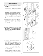
...) through the indicated hole in a Seat Plate (37). Attach the Seat Plate to the Leg Press Seat Frame with a 1/4" Washer (10) and a 1/4" x 2 1/2" Screw (43). 39. Locate and open the parts bag labeled "SEAT ASSEMBLY." Insert the 1/4" x 2 1/2" Carriage Bolt (92) through the center hole in the Leg Press Upright (56). Attach the other end of a Seat (13) to the Front Seat Frame (36) with two 1/4" x 3/4" Screws (18). Note: Make sure the...
...) through the indicated hole in a Seat Plate (37). Attach the Seat Plate to the Leg Press Seat Frame with a 1/4" Washer (10) and a 1/4" x 2 1/2" Screw (43). 39. Locate and open the parts bag labeled "SEAT ASSEMBLY." Insert the 1/4" x 2 1/2" Carriage Bolt (92) through the center hole in the Leg Press Upright (56). Attach the other end of a Seat (13) to the Front Seat Frame (36) with two 1/4" x 3/4" Screws (18). Note: Make sure the...
English Manual
Page 19
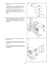
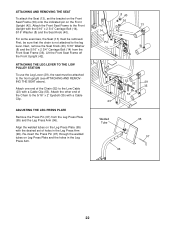
Press a 1 1/2" Square Inner Cap (32) into the Leg Lever (29). Attach the Leg Lever (29) to the Front Upright with the Bolt and a 5/16" Nylon Locknut (3). Tighten a 3/8" Washer (9) and a 3/8" Nylon Locknut (21) onto the Eyebolt. 42. Insert the other Pad Tube (28) into the Leg 41 Lever (29). Rest the Front Seat Frame (36) on the indicated pin 42 in the...
Press a 1 1/2" Square Inner Cap (32) into the Leg Lever (29). Attach the Leg Lever (29) to the Front Upright with the Bolt and a 5/16" Nylon Locknut (3). Tighten a 3/8" Washer (9) and a 3/8" Nylon Locknut (21) onto the Eyebolt. 42. Insert the other Pad Tube (28) into the Leg 41 Lever (29). Rest the Front Seat Frame (36) on the indicated pin 42 in the...
English Manual
Page 20
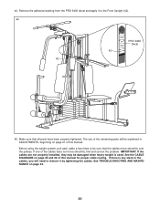
... in ADJUSTMENTS, beginning on page 21 of the remaining parts will need to remove it to be sure that all parts have been properly tightened. If there is used. The use of this manual for proper cable routing. 44. Remove the adhesive backing from the PRO 9400 decal and apply it by tightening the cables. Make sure that the cables move smoothly, find and correct the problem. Before using the weight...
... in ADJUSTMENTS, beginning on page 21 of the remaining parts will need to remove it to be sure that all parts have been properly tightened. If there is used. The use of this manual for proper cable routing. 44. Remove the adhesive backing from the PRO 9400 decal and apply it by tightening the cables. Make sure that the cables move smoothly, find and correct the problem. Before using the weight...
English Manual
Page 21
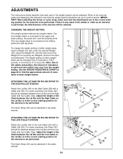
... Weights, and turn the bent end downward. CHANGING THE WEIGHT SETTING The weight system features two weight stacks. Note: Due to the cables and pulleys, the amount of resistance at each weight station. 26 25 ATTACHING THE LAT BAR OR NYLON STRAP TO THE HIGH PULLEY STATION Attach the Lat Bar (54) to the military 26 press arm and leg press. The weight setting of either weight stack, insert a Weight Pin (26) under the desired Weight (25). For some exercises...
... Weights, and turn the bent end downward. CHANGING THE WEIGHT SETTING The weight system features two weight stacks. Note: Due to the cables and pulleys, the amount of resistance at each weight station. 26 25 ATTACHING THE LAT BAR OR NYLON STRAP TO THE HIGH PULLEY STATION Attach the Lat Bar (54) to the military 26 press arm and leg press. The weight setting of either weight stack, insert a Weight Pin (26) under the desired Weight (25). For some exercises...
English Manual
Page 22
... Bolt (14) from the Leg Press Plate (95) and the Leg Press Arm (96). ATTACHING THE LEG LEVER TO THE LOW PULLEY STATION To use the Leg Lever (29), the seat must be removed. Re-insert the Press Pin (97) through the welded tubes on the Front Upright (42). Attach one end of the Chain (52) to the 5/16" x 2" Eyebolt (35) with a Cable Clip (53). For some exercises, the Seat...
... Bolt (14) from the Leg Press Plate (95) and the Leg Press Arm (96). ATTACHING THE LEG LEVER TO THE LOW PULLEY STATION To use the Leg Lever (29), the seat must be removed. Re-insert the Press Pin (97) through the welded tubes on the Front Upright (42). Attach one end of the Chain (52) to the 5/16" x 2" Eyebolt (35) with a Cable Clip (53). For some exercises, the Seat...
English Manual
Page 23
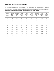
top weight. WEIGHT PLATES PRESS BUTTERFLY ARM ARM (lbs.) (lbs.) LEG LEVER (lbs.) HIGH PULLEY (lbs.) LOW PULLEY (lbs.) MILITARY PRESS ARM (lbs.) LEG PRESS (lbs.) AB...weight plates. "Top" refers to the 12.5 lb. The actual resistance at each weight station may vary due to differences in individual weight plates, as well as friction between the cables, pulleys, and weight guides. WEIGHT RESISTANCE CHART This chart shows the approximate weight resistance at each weight station. The other numbers refer to the 6.5 lb. The butterfly arm resistance listed is the resistance...
top weight. WEIGHT PLATES PRESS BUTTERFLY ARM ARM (lbs.) (lbs.) LEG LEVER (lbs.) HIGH PULLEY (lbs.) LOW PULLEY (lbs.) MILITARY PRESS ARM (lbs.) LEG PRESS (lbs.) AB...weight plates. "Top" refers to the 12.5 lb. The actual resistance at each weight station may vary due to differences in individual weight plates, as well as friction between the cables, pulleys, and weight guides. WEIGHT RESISTANCE CHART This chart shows the approximate weight resistance at each weight station. The other numbers refer to the 6.5 lb. The butterfly arm resistance listed is the resistance...
English Manual
Page 24
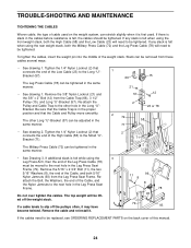
... 2. TROUBLE-SHOOTING AND MAINTENANCE TIGHTENING THE CABLES Woven cable, the type of cable used . Do not over tighten the cables. Remove the cable and re-install it. 11 96 8 8 78 93 79 93 If the cables need to the next hole in the proper position and that connects the end of the High Cable (58) to slip off the weight stack. If any slack is in the Leg Press Seat Frame. Tighten...
... 2. TROUBLE-SHOOTING AND MAINTENANCE TIGHTENING THE CABLES Woven cable, the type of cable used . Do not over tighten the cables. Remove the cable and re-install it. 11 96 8 8 78 93 79 93 If the cables need to the next hole in the proper position and that connects the end of the High Cable (58) to slip off the weight stack. If any slack is in the Leg Press Seat Frame. Tighten...
English Manual
Page 31
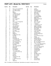
... Long Weight Guide 63 2 Weight Tube 64 2 Weight Tube Bumper 65 2 Top Weight 66 10 Cable Trap 67 2 3/8" x 3 1/4" Bolt 68 1 5/16" x 5" Bolt 69 4 1" Retainer 70 2 1" Round Cover Cap 71 2 Small "U"-Bracket 72 1 Military Press Cable 73 2 Short Weight Guide 74 1 Rear Upright 75 2 Round Inner Cap 76 1 3 1/2" Low Pulley 77 2 Pulley Cover 78 1 Leg Press Cable 79 1 Leg Press Seat Frame 80 1 Pivot Arm 81 1 1/4" x 2" Machine Screw 82 1 Handle 83 8 5" Plastic Grip 84 1 Military Press Arm 85 1 Leg Press Backrest 86 3 3/8" x 2 1/2" Bolt...
... Long Weight Guide 63 2 Weight Tube 64 2 Weight Tube Bumper 65 2 Top Weight 66 10 Cable Trap 67 2 3/8" x 3 1/4" Bolt 68 1 5/16" x 5" Bolt 69 4 1" Retainer 70 2 1" Round Cover Cap 71 2 Small "U"-Bracket 72 1 Military Press Cable 73 2 Short Weight Guide 74 1 Rear Upright 75 2 Round Inner Cap 76 1 3 1/2" Low Pulley 77 2 Pulley Cover 78 1 Leg Press Cable 79 1 Leg Press Seat Frame 80 1 Pivot Arm 81 1 1/4" x 2" Machine Screw 82 1 Handle 83 8 5" Plastic Grip 84 1 Military Press Arm 85 1 Leg Press Backrest 86 3 3/8" x 2 1/2" Bolt...
English Manual
Page 33
... to state. The SERIAL NUMBER of the product (see the PART LIST and EXPLODED DRAWING attached at 1-800-999-3756, Monday through one of whatsoever nature. This warranty gives you , please be pre-authorized by an ICON authorized service center; All repairs for commercial or rental purposes; The MODEL NUMBER of the product (WEIDER® PRO 9400 weight system) 3. Accordingly, the above limitation may not apply...
... to state. The SERIAL NUMBER of the product (see the PART LIST and EXPLODED DRAWING attached at 1-800-999-3756, Monday through one of whatsoever nature. This warranty gives you , please be pre-authorized by an ICON authorized service center; All repairs for commercial or rental purposes; The MODEL NUMBER of the product (WEIDER® PRO 9400 weight system) 3. Accordingly, the above limitation may not apply...


