

Canadian English Manual
Page 1
If you have questions, or if there are committed to providing complete customer satisfaction. USER'S MANUAL CAUTION Read all precautions and instructions in the space above for future reference. Visit our website at www.weiderplatinum.com Serial Number Decal (under seat) QUESTIONS? As a manufacturer, we are missing parts, please call: 1-888-936-4266 Mon.-Fri. 8h00 until 18h30 EST (excluding holidays). Save this equipment. Write the serial number in this manual before using this manual for future reference. Model No. 15399C1 Serial No.
If you have questions, or if there are committed to providing complete customer satisfaction. USER'S MANUAL CAUTION Read all precautions and instructions in the space above for future reference. Visit our website at www.weiderplatinum.com Serial Number Decal (under seat) QUESTIONS? As a manufacturer, we are missing parts, please call: 1-888-936-4266 Mon.-Fri. 8h00 until 18h30 EST (excluding holidays). Save this equipment. Write the serial number in this manual before using this manual for future reference. Model No. 15399C1 Serial No.
Canadian English Manual
Page 2
TABLE OF CONTENTS WARNING DECAL PLACEMENT 3 IMPORTANT PRECAUTIONS 4 BEFORE YOU BEGIN 5 ASSEMBLY 6 UPPER CABLE ADJUSTMENT 14 ADJUSTMENTS 15 CABLE DIAGRAM 18 TROUBLESHOOTING 19 EXERCISE GUIDELINES 20 ORDERING REPLACEMENT PARTS Back Cover LIMITED WARRANTY Back Cover Note: A PART IDENTIFICATION CHART and a PART LIST/EXPLODED DRAWING are attached in the center of ICON IP, Inc. 2 Remove the PART IDENTIFICATION CHART and PART LIST/EXPLODED DRAWING before beginning assembly. WEIDER is a registered trademark of this manual.
TABLE OF CONTENTS WARNING DECAL PLACEMENT 3 IMPORTANT PRECAUTIONS 4 BEFORE YOU BEGIN 5 ASSEMBLY 6 UPPER CABLE ADJUSTMENT 14 ADJUSTMENTS 15 CABLE DIAGRAM 18 TROUBLESHOOTING 19 EXERCISE GUIDELINES 20 ORDERING REPLACEMENT PARTS Back Cover LIMITED WARRANTY Back Cover Note: A PART IDENTIFICATION CHART and a PART LIST/EXPLODED DRAWING are attached in the center of ICON IP, Inc. 2 Remove the PART IDENTIFICATION CHART and PART LIST/EXPLODED DRAWING before beginning assembly. WEIDER is a registered trademark of this manual.
Canadian English Manual
Page 4
... with the seat in this product. 4 Replace any commercial, rental, or institutional setting. 4. The resistance system is designed to the upright base, or while standing on the top frame is used for persons over the age of this manual before using the resistance system. 1. Pull on the high cables only while sitting on the bench, with pre-existing health problems. Read all instructions in...
... with the seat in this product. 4 Replace any commercial, rental, or institutional setting. 4. The resistance system is designed to the upright base, or while standing on the top frame is used for persons over the age of this manual before using the resistance system. 1. Pull on the high cables only while sitting on the bench, with pre-existing health problems. Read all instructions in...
Canadian English Manual
Page 5
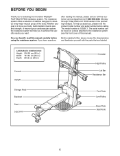
...: 203.2 cm (80 in.) Console Upright Storage Knob Backrest Seat Leg Lever Crossbar High Pulley Lat Bar Resistance Bar Foot Plate Low Pulley Base Plate Seat Knob 5 For your cardiovascular system, the resistance system will help us assist you want. after reading this manual). The model number is to the resistance system (see the front cover of the body. If you for selecting the innovative WEIDER® PLATINUM XP600 resistance system. To help you to...
...: 203.2 cm (80 in.) Console Upright Storage Knob Backrest Seat Leg Lever Crossbar High Pulley Lat Bar Resistance Bar Foot Plate Low Pulley Base Plate Seat Knob 5 For your cardiovascular system, the resistance system will help us assist you want. after reading this manual). The model number is to the resistance system (see the front cover of the body. If you for selecting the innovative WEIDER® PLATINUM XP600 resistance system. To help you to...
Canadian English Manual
Page 6
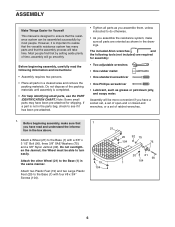
... has been pre-attached. • Tighten all parts as you assemble them, unless instructed to the Base (1) with a 3/8" x 3 1/2" Bolt (90), three 3/8" SAE Washers (75), and a 3/8" Nylon Jamnut (92). Assembly will go smoothly. Attach two Plastic Feet (19) and two Large Plastic Feet (20) to do otherwise. • As you assemble the resistance system, make sure that the assembly process will take...
... has been pre-attached. • Tighten all parts as you assemble them, unless instructed to the Base (1) with a 3/8" x 3 1/2" Bolt (90), three 3/8" SAE Washers (75), and a 3/8" Nylon Jamnut (92). Assembly will go smoothly. Attach two Plastic Feet (19) and two Large Plastic Feet (20) to do otherwise. • As you assemble the resistance system, make sure that the assembly process will take...

Canadian English Manual
Page 8
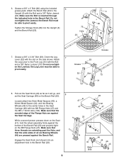
... of the lower wire harness (A) into the Upright (3). Insert the connector of the Front Leg Foot is taller than the back. Attach the Mech Assembly (6) to the Upright (3) with the four M10 Nylon Locknuts (71). 4. Attach the Mech Assembly to the Base (1) with a 1/2" x 3" Carriage Bolt (79) and a 1/2" Nylon Locknut (78). Pull the excess lower wire harness (A) out of the Front Leg (31). Tighten the...
... of the lower wire harness (A) into the Upright (3). Insert the connector of the Front Leg Foot is taller than the back. Attach the Mech Assembly (6) to the Upright (3) with the four M10 Nylon Locknuts (71). 4. Attach the Mech Assembly to the Base (1) with a 1/2" x 3" Carriage Bolt (79) and a 1/2" Nylon Locknut (78). Pull the excess lower wire harness (A) out of the Front Leg (31). Tighten the...
Canadian English Manual
Page 9
... pivot easily. Orient the Leg 7 Lever (32) with the Bolt and a 3/8" Nylon Locknut (73). While a second person presses down on the Seat (41), hold the wheel assembly firmly against the Bench Rail. en the Locknut; Do not overtight- Grease 93 Grease 32 Slot 73 31 8. Tighten the Storage Knob (26) into an adjustment hole in the Bench Rail. Attach the Leg Lever to the Front...
... pivot easily. Orient the Leg 7 Lever (32) with the Bolt and a 3/8" Nylon Locknut (73). While a second person presses down on the Seat (41), hold the wheel assembly firmly against the Bench Rail. en the Locknut; Do not overtight- Grease 93 Grease 32 Slot 73 31 8. Tighten the Storage Knob (26) into an adjustment hole in the Bench Rail. Attach the Leg Lever to the Front...
Canadian English Manual
Page 11
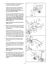
... each other side of the Mech Assembly (6), up between the two Pulleys. Attach a Tether (61) to the Lat Tower (5) with an M12 x 58mm Button Bolt (81) and an M12 Nylon Locknut (72). Press a Pulley Bracket (10) onto the Resistance Bar (9). Attach another 3/8" x 6" Bolt (83). 12. Tighten the M12 Nylon Locknuts (72) used in steps 11 and 12 (see the CABLE DIA- Repeat on the other 13...
... each other side of the Mech Assembly (6), up between the two Pulleys. Attach a Tether (61) to the Lat Tower (5) with an M12 x 58mm Button Bolt (81) and an M12 Nylon Locknut (72). Press a Pulley Bracket (10) onto the Resistance Bar (9). Attach another 3/8" x 6" Bolt (83). 12. Tighten the M12 Nylon Locknuts (72) used in steps 11 and 12 (see the CABLE DIA- Repeat on the other 13...
Canadian English Manual
Page 12
... sure that is routed as shown in the Front Leg (31), and attach it inside of turns. Hold a Large Pulley (17) inside of turns. 17. Insert the rod on page 18. Screw two 3/8" x 1 1/2" Tension Screws (106) into the slot in the Seat Carriage (48). Attach the two Guard Plates (63) to a Pulley Bracket (10) with an M12 x 58mm Button Bolt (81) and an...
... sure that is routed as shown in the Front Leg (31), and attach it inside of turns. Hold a Large Pulley (17) inside of turns. 17. Insert the rod on page 18. Screw two 3/8" x 1 1/2" Tension Screws (106) into the slot in the Seat Carriage (48). Attach the two Guard Plates (63) to a Pulley Bracket (10) with an M12 x 58mm Button Bolt (81) and an...
Canadian English Manual
Page 13
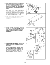
... heavy resistance is above the Leg Lever Cable (62). The use of the Bench Rail (23). 21. If the cable does not move smoothly, find and correct the problem. Make sure that it moves smoothly over a 3 1/2" Pulley 22 (89). IMPORTANT: If the cables are not properly installed, they may be explained in UPPER CABLE ADJUSTMENT on page 18 for proper cable routing. 13 Slide the two free...
... heavy resistance is above the Leg Lever Cable (62). The use of the Bench Rail (23). 21. If the cable does not move smoothly, find and correct the problem. Make sure that it moves smoothly over a 3 1/2" Pulley 22 (89). IMPORTANT: If the cables are not properly installed, they may be explained in UPPER CABLE ADJUSTMENT on page 18 for proper cable routing. 13 Slide the two free...
Canadian English Manual
Page 14
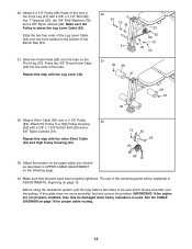
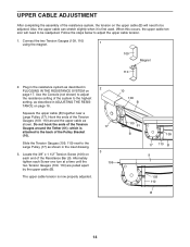
...); The upper cable tension is first used. Use the Console (not shown) to the highest setting, as shown. Alternately tighten each end of the Pulley Bracket (10). which is attached to be adjusted. When this occurs, the upper cable tension will need to the back of the Resistance Bar (9). Connect the two Tension Gauges (109, 110) 1 using the magnet. 109 Magnet 110 2. Locate the 3/8" x 1 1/2" Tension Screw (106...
...); The upper cable tension is first used. Use the Console (not shown) to the highest setting, as shown. Alternately tighten each end of the Pulley Bracket (10). which is attached to be adjusted. When this occurs, the upper cable tension will need to the back of the Resistance Bar (9). Connect the two Tension Gauges (109, 110) 1 using the magnet. 109 Magnet 110 2. Locate the 3/8" x 1 1/2" Tension Screw (106...
Canadian English Manual
Page 15
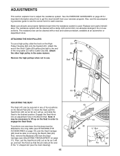
.... Attach the other high pulley in the Bench Rail. ADJUSTMENTS This section explains how to see the correct form for important information about how to lift up on the Seat in any of the "L"-shaped slot (see the inset drawing). 15 64 C 40 41 48 23 43 "L"-Slot 48 Pin 43 Also, see the accompanying exercise guide to adjust the resistance system...
.... Attach the other high pulley in the Bench Rail. ADJUSTMENTS This section explains how to see the correct form for important information about how to lift up on the Seat in any of the "L"-shaped slot (see the inset drawing). 15 64 C 40 41 48 23 43 "L"-Slot 48 Pin 43 Also, see the accompanying exercise guide to adjust the resistance system...
Canadian English Manual
Page 16
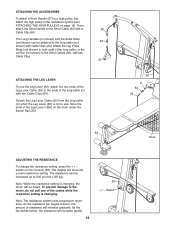
... Cable (62) from the long cable (C) when the Leg Lever (32) is changing. The resistance can be attached to the resistance system (see ATTACHING THE HIGH PULLEYS on page 15). The display will increase rapidly. 16 53 + / - Note: While the resistance setting is changing, the motor will increase gradually. Note: The resistance system uses progressive resistance. Attach the Leg Press Strap (not shown) to both ends of the long cable, or the Lat Bar...
... Cable (62) from the long cable (C) when the Leg Lever (32) is changing. The resistance can be attached to the resistance system (see ATTACHING THE HIGH PULLEYS on page 15). The display will increase rapidly. 16 53 + / - Note: While the resistance setting is changing, the motor will increase gradually. Note: The resistance system uses progressive resistance. Attach the Leg Press Strap (not shown) to both ends of the long cable, or the Lat Bar...
Canadian English Manual
Page 17
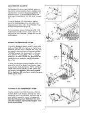
... tighten the Storage Knob into a 120-volt outlet. To move the resistance system, place the toe of the Bench Rail (23). Important: Always plug in this area 3 26 41 32 62 23 31 1 21 Hook 8 12 17 Plug the other three adjustment holes in an inclined position, secure the Seat Carriage (48) to the new location. The motor may be used in the Seat Carriage...
... tighten the Storage Knob into a 120-volt outlet. To move the resistance system, place the toe of the Bench Rail (23). Important: Always plug in this area 3 26 41 32 62 23 31 1 21 Hook 8 12 17 Plug the other three adjustment holes in an inclined position, secure the Seat Carriage (48) to the new location. The motor may be used in the Seat Carriage...
Canadian English Manual
Page 19
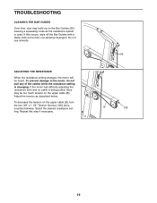
TROUBLESHOOTING CLEANING THE BAR GUIDES Over time, dust may be heard. If this step if necessary. 55 B 106 19 ADJUSTING THE RESISTANCE When the resistance setting changes, the motor will be too much tension on the upper cable (B), turn the two 3/8" x 1 1/2" Tension Screws (106) twice, counterclockwise. If the motor has difficulty adjusting the resistance level and no cable is being pulled, there may build up on the Bar Guides (55...
TROUBLESHOOTING CLEANING THE BAR GUIDES Over time, dust may be heard. If this step if necessary. 55 B 106 19 ADJUSTING THE RESISTANCE When the resistance setting changes, the motor will be too much tension on the upper cable (B), turn the two 3/8" x 1 1/2" Tension Screws (106) twice, counterclockwise. If the motor has difficulty adjusting the resistance level and no cable is being pulled, there may build up on the Bar Guides (55...
Canadian English Manual
Page 20
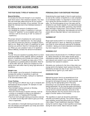
... form for each week to give balance and variety to avoid overdoing it . Weight Loss To lose weight, use a low amount of resistance and increase the number of resistance. An example of a balanced program is important to your body's signals. Determining the exact length of time for several exercises, and a list of each exercise you feeling exhausted. It is : • Plan strength training workouts...
... form for each week to give balance and variety to avoid overdoing it . Weight Loss To lose weight, use a low amount of resistance and increase the number of resistance. An example of a balanced program is important to your body's signals. Determining the exact length of time for several exercises, and a list of each exercise you feeling exhausted. It is : • Plan strength training workouts...
Canadian English Manual
Page 21
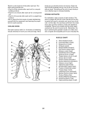
...Move slowly as you stretch and do not bounce. The chart on pages 22 and 23 of this manual can without strain. Remember, the key to achieving the greatest results is an effective way to make exercise a regular and enjoyable part...workouts. List the date, the exercises performed, the resistance used to spend the first couple of each set for a muscle building workout. • Rest for one minute after each exercise. Record your arms and legs. Brachioradials (forearm) F. Quadriceps (front of sets and repetitions completed. Posterior Deltoid (shoulder) R. Spinae Erectors (lower...
...Move slowly as you stretch and do not bounce. The chart on pages 22 and 23 of this manual can without strain. Remember, the key to achieving the greatest results is an effective way to make exercise a regular and enjoyable part...workouts. List the date, the exercises performed, the resistance used to spend the first couple of each set for a muscle building workout. • Rest for one minute after each exercise. Record your arms and legs. Brachioradials (forearm) F. Quadriceps (front of sets and repetitions completed. Posterior Deltoid (shoulder) R. Spinae Erectors (lower...
Canadian English Manual
Page 24
... following information: • The MODEL NUMBER of the product (15399C1) • The NAME of the product (WEIDER® PLATINUM XP600 resistance system) • The SERIAL NUMBER of the product (see the front cover of this product to be pre-authorized by ICON. This warranty extends only to you. ICON's obligation under normal use , costs of removal, installation or other rights which warranty claims are made must be free...
... following information: • The MODEL NUMBER of the product (15399C1) • The NAME of the product (WEIDER® PLATINUM XP600 resistance system) • The SERIAL NUMBER of the product (see the front cover of this product to be pre-authorized by ICON. This warranty extends only to you. ICON's obligation under normal use , costs of removal, installation or other rights which warranty claims are made must be free...

Canadian English Manual
Page 25
... parts used in the center of the part, from the PART LIST in assembly. PART IDENTIFICATION CHART See the drawings below to see if it has been pre-attached. The number in parentheses by each drawing is missing, call toll-free 1-888-936-4266. If a part is the key number of this manual. M10 Nylon Locknut (71) 1/2" Nylon Locknut (78) M12 x 58mm Button Bolt (81) M12 x 62mm Button Bolt...
... parts used in the center of the part, from the PART LIST in assembly. PART IDENTIFICATION CHART See the drawings below to see if it has been pre-attached. The number in parentheses by each drawing is missing, call toll-free 1-888-936-4266. If a part is the key number of this manual. M10 Nylon Locknut (71) 1/2" Nylon Locknut (78) M12 x 58mm Button Bolt (81) M12 x 62mm Button Bolt...
Canadian English Manual
Page 26
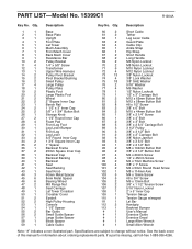
Description Key No. Specifications are subject to change without notice. If a part is missing, call toll-free 1-888-936-4266. Qty. See the back cover of this manual for information about ordering replacement parts. PART LIST-Model No. 15399C1 R1204A Key No. Description 1 1 Base 2 1 Base Plate 3 1 Upright 4 1 Foot Plate 5 1 Lat Tower 6 1 Mech Assembly 7 1 Front Mech Cover 8 1 Back Mech Cover 9 1 Resistance Bar 10 2 Pulley Bracket 11 4 1/4" x 5/8" Screw 12 1 Transformer 13 1 Upper Wire Harness 14 2 Pulley Pivot Bracket...
Description Key No. Specifications are subject to change without notice. If a part is missing, call toll-free 1-888-936-4266. Qty. See the back cover of this manual for information about ordering replacement parts. PART LIST-Model No. 15399C1 R1204A Key No. Description 1 1 Base 2 1 Base Plate 3 1 Upright 4 1 Foot Plate 5 1 Lat Tower 6 1 Mech Assembly 7 1 Front Mech Cover 8 1 Back Mech Cover 9 1 Resistance Bar 10 2 Pulley Bracket 11 4 1/4" x 5/8" Screw 12 1 Transformer 13 1 Upper Wire Harness 14 2 Pulley Pivot Bracket...


