
English Manual
Page 2
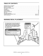
... order a free replacement decal. Apply the decal in the location shown. WEIDER is missing or illegible, call the toll-free telephone number on the weight system. TABLE OF CONTENTS WARNING DECAL PLACEMENT 2 IMPORTANT PRECAUTIONS 3 BEFORE YOU BEGIN 4 PART IDENTIFICATION CHART 5 ASSEMBLY 7 ADJUSTMENTS 25 CABLE DIAGRAM 28 EXERCISE GUIDELINES 29 PART LIST 32...
... order a free replacement decal. Apply the decal in the location shown. WEIDER is missing or illegible, call the toll-free telephone number on the weight system. TABLE OF CONTENTS WARNING DECAL PLACEMENT 2 IMPORTANT PRECAUTIONS 3 BEFORE YOU BEGIN 4 PART IDENTIFICATION CHART 5 ASSEMBLY 7 ADJUSTMENTS 25 CABLE DIAGRAM 28 EXERCISE GUIDELINES 29 PART LIST 32...
English Manual
Page 4
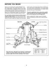
... Lever Right Side Left Side High Pulley Station Lat Bar Military Press Arm Adjustable Backrest Press Arm Seat Leg Press Low Pulley Station 12.5-lb. ASSEMBLED DIMENSIONS: Height: 81 in. / 206 cm Width: 82 in. / 208 cm Depth: 89 in the manual. For your cardiovascular system, the weight system will help... cover of the body. The serial number can be found on the seat; To help you want. To avoid a registration fee for selecting the versatile WEIDER® Club 4870 weight system.
... Lever Right Side Left Side High Pulley Station Lat Bar Military Press Arm Adjustable Backrest Press Arm Seat Leg Press Low Pulley Station 12.5-lb. ASSEMBLED DIMENSIONS: Height: 81 in. / 206 cm Width: 82 in. / 208 cm Depth: 89 in the manual. For your cardiovascular system, the weight system will help... cover of the body. The serial number can be found on the seat; To help you want. To avoid a registration fee for selecting the versatile WEIDER® Club 4870 weight system.
English Manual
Page 5
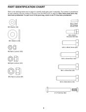
... Shoulder Bolt (92) M10 x 35mm Screw (89) M10 x 40mm Bolt (104) M10 x 45mm Bolt (95) M10 x 50mm Bolt (105) 2 1/4" Bolt Set (86) 5 The number in assembly. If a part is not in the parts bag, check to identify small parts used in parentheses by each drawing is the key number of the...
... Shoulder Bolt (92) M10 x 35mm Screw (89) M10 x 40mm Bolt (104) M10 x 45mm Bolt (95) M10 x 50mm Bolt (105) 2 1/4" Bolt Set (86) 5 The number in assembly. If a part is not in the parts bag, check to identify small parts used in parentheses by each drawing is the key number of the...
English Manual
Page 7
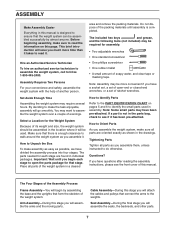
...packages. Note: Some small parts may be required for the Weight System Because of its weight and size, the weight system should be assembled in the location where it has been pre-attached. Questions? Hire an Authorized Service Technician To hire an authorized service technician to open... than it takes to walk around the weight system as shown in the parts bag, check to do otherwise. Before beginning assembly, make the task enjoyable, assembly will assemble the arms and the moving parts. This brief introduction will save you much more convenient if you have a socket set,...
...packages. Note: Some small parts may be required for the Weight System Because of its weight and size, the weight system should be assembled in the location where it has been pre-attached. Questions? Hire an Authorized Service Technician To hire an authorized service technician to open... than it takes to walk around the weight system as shown in the parts bag, check to do otherwise. Before beginning assembly, make the task enjoyable, assembly will assemble the arms and the moving parts. This brief introduction will save you much more convenient if you have a socket set,...
English Manual
Page 8
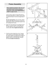
..., use the PART IDENTIFICATION CHART on the previous page. Attach the Center Base (5) to hold the Carriage Bolts in the box on pages 5 and 6. Frame Assembly 1. Insert four M10 x 80mm Carriage Bolts (88) up through the Right Base (1). Orient the Center Upright (9) so the 2" Square 3 Inner Cap (51) is in place... Washers (108), and two M10 Nylon Locknuts (84). Do not tighten the Bolts yet. 1 1 88 2 88 2 57 108 1 88 84 84 5 57 108 2 3. Before beginning assembly, make sure you understand the information in place. 2.
..., use the PART IDENTIFICATION CHART on the previous page. Attach the Center Base (5) to hold the Carriage Bolts in the box on pages 5 and 6. Frame Assembly 1. Insert four M10 x 80mm Carriage Bolts (88) up through the Right Base (1). Orient the Center Upright (9) so the 2" Square 3 Inner Cap (51) is in place... Washers (108), and two M10 Nylon Locknuts (84). Do not tighten the Bolts yet. 1 1 88 2 88 2 57 108 1 88 84 84 5 57 108 2 3. Before beginning assembly, make sure you understand the information in place. 2.
English Manual
Page 12
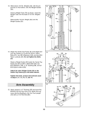
... Center Top Frame (6) in steps 3, 4, 7, 9, 10, 11, and 14. 14 84 108 84 6 68 57 87 108 108 3 68 87 57 108 4 30 30 Arm Assembly 15 15. Slide eleven 12.5-lb. Do not tighten the Bolts yet. Tighten the bolts, screws and locknuts used in the same manner. Weights (34...
... Center Top Frame (6) in steps 3, 4, 7, 9, 10, 11, and 14. 14 84 108 84 6 68 57 87 108 108 3 68 87 57 108 4 30 30 Arm Assembly 15 15. Slide eleven 12.5-lb. Do not tighten the Bolts yet. Tighten the bolts, screws and locknuts used in the same manner. Weights (34...
English Manual
Page 15
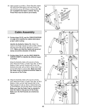
... the Cable to hold the Cable in the groove of pulleys. Wrap the Butterfly Cable (73) around the shoulder of the Pulley. 26. 23. Cable Assembly 24 24. Identify the Butterfly Cable (73). Make sure that the Cable Trap is oriented to the Left Butterfly Arm (22) with the Bolt and...
... the Cable to hold the Cable in the groove of pulleys. Wrap the Butterfly Cable (73) around the shoulder of the Pulley. 26. 23. Cable Assembly 24 24. Identify the Butterfly Cable (73). Make sure that the Cable Trap is oriented to the Left Butterfly Arm (22) with the Bolt and...
English Manual
Page 22
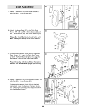
Seat Assembly 51. Attach a Backrest (35) to the Right Seat 52 Frame (17) with four M6 x 16mm Screws (99). 51 35 99 7 99 52. Attach the Large ...
Seat Assembly 51. Attach a Backrest (35) to the Right Seat 52 Frame (17) with four M6 x 16mm Screws (99). 51 35 99 7 99 52. Attach the Large ...
English Manual
Page 28
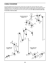
... traps, and the guards have not been correctly routed, the weight system will not function properly and damage may occur. If the cables have been assembled correctly. The numbers show the proper routing of the Low Cable (70), the Press Cable (72), and the Butterfly Cable (73). Use the diagrams to...
... traps, and the guards have not been correctly routed, the weight system will not function properly and damage may occur. If the cables have been assembled correctly. The numbers show the proper routing of the Low Cable (70), the Press Cable (72), and the Butterfly Cable (73). Use the diagrams to...


