
English Owners Manual
Page 9
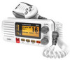
... channel) SCAN/MEM button DOWN button (move down the channels. Move quickly down a channel) Button ( ) ( ) Press to 16.0 VDC) (Red wire +, black wire -). External VHF antenna with negative ground (10.5 VDC to ... Connecting the radio (see page 33). Move quickly up one channel at a time. Nominal 13.8 VDC power supply with... a male PL259 (SO238) connector and 50 Ω impedance. Move up the channels. Accessory cable GPS receiver, GPS chartplotter. Minimum 4 ft, 3dB rated antenna for sailboats, 8 ft, 6 dB rated for power boats. Press and hold to ...
... channel) SCAN/MEM button DOWN button (move down the channels. Move quickly down a channel) Button ( ) ( ) Press to 16.0 VDC) (Red wire +, black wire -). External VHF antenna with negative ground (10.5 VDC to ... Connecting the radio (see page 33). Move quickly up one channel at a time. Nominal 13.8 VDC power supply with... a male PL259 (SO238) connector and 50 Ω impedance. Move up the channels. Accessory cable GPS receiver, GPS chartplotter. Minimum 4 ft, 3dB rated antenna for sailboats, 8 ft, 6 dB rated for power boats. Press and hold to ...
English Owners Manual
Page 32
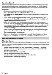
... shorter than 12 characters, press and hold the radio, depending on the surface. Keep the battery leads as short as possible. Keep the antenna lead-in wire as short as possible. Allow free air flow around the heat sink on page 40 for you to use some type...
... shorter than 12 characters, press and hold the radio, depending on the surface. Keep the battery leads as short as possible. Keep the antenna lead-in wire as short as possible. Allow free air flow around the heat sink on page 40 for you to use some type...
English Owners Manual
Page 33
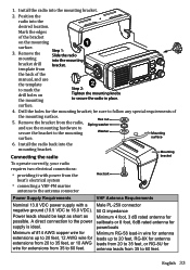
...Minimum of the manual, and use the mounting hardware to secure the bracket to the power sailboats or 8 foot, 6dB rated antenna for possible. Position the radio into the mounting bracket drill bracket. Mark the edges of the mounting surface. 5. Drill the ... Step 1: Slide the radio mounting into the desired location. surface 6. antenna leads from the boat's electrical system Hex bolt connecting a VHF-FM marine antenna to the antenna connector Power Supply Requirements VHF Antenna Requirements Nominal 13.8 VDC power supply with a Male PL-259 connector ...
...Minimum of the manual, and use the mounting hardware to secure the bracket to the power sailboats or 8 foot, 6dB rated antenna for possible. Position the radio into the mounting bracket drill bracket. Mark the edges of the mounting surface. 5. Drill the ... Step 1: Slide the radio mounting into the desired location. surface 6. antenna leads from the boat's electrical system Hex bolt connecting a VHF-FM marine antenna to the antenna connector Power Supply Requirements VHF Antenna Requirements Nominal 13.8 VDC power supply with a Male PL-259 connector ...

English Owners Manual
Page 34
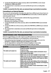
...-in connector, male PL-259 Connecting to a GPS receiver If you connect the radio to a GPS receiver, the radio can automatically transmit your antenna according to 3 dB be installed at least 6 feet away.) 6. Install your current position during an automated distress call or during a normal DSC...and Installation on the back of your power source. 3. Connect the BLACK wire of the power cable to the SO238 connector labeled ANTENNA on page 51 for antenna separation. Connect the RED wire of the power cable to your power source. 2. Connect the PL-259 connector from a GPS ...
...-in connector, male PL-259 Connecting to a GPS receiver If you connect the radio to a GPS receiver, the radio can automatically transmit your antenna according to 3 dB be installed at least 6 feet away.) 6. Install your current position during an automated distress call or during a normal DSC...and Installation on the back of your power source. 3. Connect the BLACK wire of the power cable to the SO238 connector labeled ANTENNA on page 51 for antenna separation. Connect the RED wire of the power cable to your power source. 2. Connect the PL-259 connector from a GPS ...
English Owners Manual
Page 37
...radio. You should not transmit except in the case of your radio. You are not in a noisy environment. A defective antenna may cause damage to its rugged design, your chartplotter's NMEA data INPUT 3. Check the fuse. Make sure you are responsible for continued FCC ...connect to the POSITIVE (+) wire of each transmission is a precision electronic instrument, so you should follow a few precautions: If the antenna has been damaged, you adjust the VOLUME-PWR knob on . Your radio supports an external speaker with your external speaker. 2. Be certain all...
...radio. You should not transmit except in the case of your radio. You are not in a noisy environment. A defective antenna may cause damage to its rugged design, your chartplotter's NMEA data INPUT 3. Check the fuse. Make sure you are responsible for continued FCC ...connect to the POSITIVE (+) wire of each transmission is a precision electronic instrument, so you should follow a few precautions: If the antenna has been damaged, you adjust the VOLUME-PWR knob on . Your radio supports an external speaker with your external speaker. 2. Be certain all...
English Owners Manual
Page 39
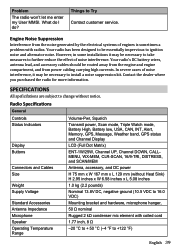
...to install a noise suppression kit. Radio Specifications General Controls Status Indicators Display Buttons Connectors and Cables Size Weight Supply Voltage Standard Accessories Antenna Impedance Microphone Speaker Operating Temperature Range Volume-Pwr, Squelch Transmit power, Scan mode, Triple Watch mode, Battery High, Battery low,..., and from the noise generated by the electrical systems of noise interference. Your radio's DC battery wires, antenna lead, and accessory cables should be essentially impervious to Try Contact customer service. Engine Noise Suppression Interference from ...
...to install a noise suppression kit. Radio Specifications General Controls Status Indicators Display Buttons Connectors and Cables Size Weight Supply Voltage Standard Accessories Antenna Impedance Microphone Speaker Operating Temperature Range Volume-Pwr, Squelch Transmit power, Scan mode, Triple Watch mode, Battery High, Battery low,..., and from the noise generated by the electrical systems of noise interference. Your radio's DC battery wires, antenna lead, and accessory cables should be essentially impervious to Try Contact customer service. Engine Noise Suppression Interference from ...
English Owners Manual
Page 51
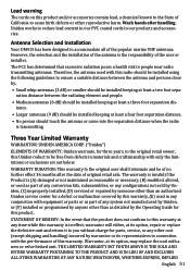
...conversion kits, subassemblies, or any configurations not sold by Uniden, (C) improperly installed, (D) serviced or repaired by someone other than as part of any other reproductive harm. Antenna Selection and Installation Your UM415 has been designed to accommodate all of the user ... IMPLIED English 51 However, the selection and the installation of the antenna is the responsibility of the popular marine VHF antennas. Three Year Limited Warranty WARRANTOR: UNIDEN AMERICA CORP. ("Uniden") ELEMENTS OF WARRANTY: Uniden warrants, for this product. STATEMENT OF REMEDY: In the event...
...conversion kits, subassemblies, or any configurations not sold by Uniden, (C) improperly installed, (D) serviced or repaired by someone other than as part of any other reproductive harm. Antenna Selection and Installation Your UM415 has been designed to accommodate all of the user ... IMPLIED English 51 However, the selection and the installation of the antenna is the responsibility of the popular marine VHF antennas. Three Year Limited Warranty WARRANTOR: UNIDEN AMERICA CORP. ("Uniden") ELEMENTS OF WARRANTY: Uniden warrants, for this product. STATEMENT OF REMEDY: In the event...

