English Owners Manual
Page 3
... Wiring 4 Power Cable Wiring 4 Installing The Transducer 5 Transom Mount Transducers 5 Through-the-hull Transducers 8 Low Profile Transducers 9 Stem-type (power Boat Bronze) Transducers 10 Inside-the-hull Transducers 12 Understanding Sonar 14 Air Echoes 14 Setting The Shallow Water Alarm 15 Shallow Water Sensitivity 16 When to Use Less Sensitivity 17 When to Use More Sensitivity 18 Troubleshooting Guideline 19 Features, Specifications, and...
... Wiring 4 Power Cable Wiring 4 Installing The Transducer 5 Transom Mount Transducers 5 Through-the-hull Transducers 8 Low Profile Transducers 9 Stem-type (power Boat Bronze) Transducers 10 Inside-the-hull Transducers 12 Understanding Sonar 14 Air Echoes 14 Setting The Shallow Water Alarm 15 Shallow Water Sensitivity 16 When to Use Less Sensitivity 17 When to Use More Sensitivity 18 Troubleshooting Guideline 19 Features, Specifications, and...
English Owners Manual
Page 4
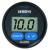
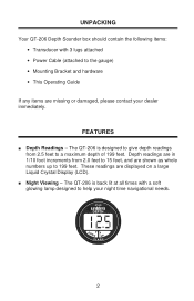
... • Power Cable (attached to help your dealer immediately. The QT-206 is designed to give depth readings from 2.0 feet to 15 feet, and are missing or damaged, please contact your night time navigational needs. 2 FEATURES n Depth Readings - n Night Viewing - These readings are in 1/10 foot increments from 2.5 feet to 199 feet. Depth readings are displayed on...
... • Power Cable (attached to help your dealer immediately. The QT-206 is designed to give depth readings from 2.0 feet to 15 feet, and are missing or damaged, please contact your night time navigational needs. 2 FEATURES n Depth Readings - n Night Viewing - These readings are in 1/10 foot increments from 2.5 feet to 199 feet. Depth readings are displayed on...
English Owners Manual
Page 5
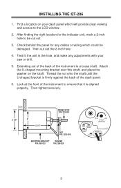
... 1/2" BRASS STUD P/N: 210-005 2 3/8" 2" 2 1/2" NUT P/N: 3203-009 MOUNTING BRACKET WASHER P/N: 950-025 P/N: 308-029 X-ducer Red Black Shield Alarm More Less Shallow Sensitivity Power + 3 Check behind the panel for the indicator unit, mark a 2-inch hole to ensure that it is aligned properly. Look at the ...the shaft. Test fit the unit in the hole, and make any cables or wiring which will provide clear viewing and access to the LCD window. 2. Then cut out. 3. Thread the nut onto the shaft until the U-shaped bracket is a brass shaft. INSTALLING THE QT-206 1. After ...
... 1/2" BRASS STUD P/N: 210-005 2 3/8" 2" 2 1/2" NUT P/N: 3203-009 MOUNTING BRACKET WASHER P/N: 950-025 P/N: 308-029 X-ducer Red Black Shield Alarm More Less Shallow Sensitivity Power + 3 Check behind the panel for the indicator unit, mark a 2-inch hole to ensure that it is aligned properly. Look at the ...the shaft. Test fit the unit in the hole, and make any cables or wiring which will provide clear viewing and access to the LCD window. 2. Then cut out. 3. Thread the nut onto the shaft until the U-shaped bracket is a brass shaft. INSTALLING THE QT-206 1. After ...
English Owners Manual
Page 6
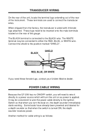
... wire it directly to the Ignition Switch so that when the switch is wired with 3 female lugs attached. TRANSDUCER WIRING On the rear of the unit, locate the terminal lugs extending out of the rear of the gauge. When shipped from the factory, the transducer is turned ON, the depth sounder receives power. These lugs need these female lugs, contact your Uniden Marine dealer. POWER CABLE WIRING...
... wire it directly to the Ignition Switch so that when the switch is wired with 3 female lugs attached. TRANSDUCER WIRING On the rear of the unit, locate the terminal lugs extending out of the rear of the gauge. When shipped from the factory, the transducer is turned ON, the depth sounder receives power. These lugs need these female lugs, contact your Uniden Marine dealer. POWER CABLE WIRING...
English Owners Manual
Page 7
..., or on the side of the transducer. TRANSOM MOUNT TRANSDUCERS Selecting An Installation Location Mount the transducer fairly close to a 12-volt battery using the power cable supplied with a 1 amp fuse, normal blow. Connect the main unit to the centerline (keel) of current when it can be used effectively if installation procedures are : • TRANSOM MOUNT - The unit consumes 0.25 amps of the boat, which...
..., or on the side of the transducer. TRANSOM MOUNT TRANSDUCERS Selecting An Installation Location Mount the transducer fairly close to a 12-volt battery using the power cable supplied with a 1 amp fuse, normal blow. Connect the main unit to the centerline (keel) of current when it can be used effectively if installation procedures are : • TRANSOM MOUNT - The unit consumes 0.25 amps of the boat, which...
English Owners Manual
Page 8
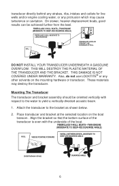
... below. 2. Place transducer and bracket at the selected location on the mounting hardware or transducer. THIS WILL DESTROY THE PLASTIC MATERIAL OF THE TRANSDUCER AND THE BRACKET. Mounting The Transducer The transducer and bracket assembly should be achieved further from the...) HULL WEDGE POINTING FORWARD INSTALL BETWEEN DRIVES-MODERATE TO DEEP-VEE DEADRISE ANGLE (Install between drives) DEADRISE ANGLE 6 DO NOT INSTALL YOUR TRANSDUCER UNDERNEATH A GASOLINE OVERFLOW. Attach the transducer to yield a vertically-directed acoustic beam. 1. Also, do not use LOCKTITE® or any ...
... below. 2. Place transducer and bracket at the selected location on the mounting hardware or transducer. THIS WILL DESTROY THE PLASTIC MATERIAL OF THE TRANSDUCER AND THE BRACKET. Mounting The Transducer The transducer and bracket assembly should be achieved further from the...) HULL WEDGE POINTING FORWARD INSTALL BETWEEN DRIVES-MODERATE TO DEEP-VEE DEADRISE ANGLE (Install between drives) DEADRISE ANGLE 6 DO NOT INSTALL YOUR TRANSDUCER UNDERNEATH A GASOLINE OVERFLOW. Attach the transducer to yield a vertically-directed acoustic beam. 1. Also, do not use LOCKTITE® or any ...
English Owners Manual
Page 9
...vertical adjustment which can accumulate rapidly on the hull. Tighten all bolts and screws. 5. Transducer Replacement/Identification Tag On most transducers manufactured after 1987, the operating frequency and part number is attached to the cable or is kept in saltwater, especially in reduced performance of time ... reduce performance. The QT-206 operates at 200 kHz. (Incorrect frequency will help you identify the operating frequency of the screws to prevent water seepage into the water to establish good contact with a 9/64" drill. Using the sheet metal screws provided, ...
...vertical adjustment which can accumulate rapidly on the hull. Tighten all bolts and screws. 5. Transducer Replacement/Identification Tag On most transducers manufactured after 1987, the operating frequency and part number is attached to the cable or is kept in saltwater, especially in reduced performance of time ... reduce performance. The QT-206 operates at 200 kHz. (Incorrect frequency will help you identify the operating frequency of the screws to prevent water seepage into the water to establish good contact with a 9/64" drill. Using the sheet metal screws provided, ...
English Owners Manual
Page 10
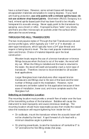
... used in diameter, or stem-type transducers, which attenuate the sound energy. If you need anti-fouling protection, use of... Choice of fittings used are better suited for all wooden boat applications. Selecting an Installation Location The mounting location must provide ...mount the transducer where the acoustic beam will dry out. Never apply paint to the transducer by the keel. Larger fiberglass boat manufacturers often request bronze transducers and fittings due to the size of the boat and the total number of material depends upon the boat construction: Wooden boats require the use...
... used in diameter, or stem-type transducers, which attenuate the sound energy. If you need anti-fouling protection, use of... Choice of fittings used are better suited for all wooden boat applications. Selecting an Installation Location The mounting location must provide ...mount the transducer where the acoustic beam will dry out. Never apply paint to the transducer by the keel. Larger fiberglass boat manufacturers often request bronze transducers and fittings due to the size of the boat and the total number of material depends upon the boat construction: Wooden boats require the use...
English Owners Manual
Page 11
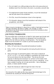
...style of the hull while preventing the transducer lock nut from the bow to the stern, to provide a smooth ride. • On displacement power boats (trawlers), mount the transducer well aft and close to the centerline. • On I/Os, mount the transducer close to the engine(s). •... a plastic housing, do not use this is ideal for high speed sport boats and sailboats. LOW PROFILE TRANSDUCERS The low profile style of transducer is the area where air bubbles travel from unwinding. • Do not install it on the cable as a guide. 3. Mounting the Transducer 1. IMPORTANT Do not...
...style of the hull while preventing the transducer lock nut from the bow to the stern, to provide a smooth ride. • On displacement power boats (trawlers), mount the transducer well aft and close to the centerline. • On I/Os, mount the transducer close to the engine(s). •... a plastic housing, do not use this is ideal for high speed sport boats and sailboats. LOW PROFILE TRANSDUCERS The low profile style of transducer is the area where air bubbles travel from unwinding. • Do not install it on the cable as a guide. 3. Mounting the Transducer 1. IMPORTANT Do not...
English Owners Manual
Page 12
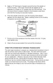
... of 1/4" greater than the hull thickness. The stem will be best suited for your hull and the style of the block will fit the same size hole as oak. The shape of transducer you choose. 10 Apply a 1/8" thick layer of your application. If nylon, hand tighten only. 8. 5. This...SEALANT 7. Also, if your hull has a steep dead rise, the stem-type transducer will ensure there is popular as a replacement transducer since it was the primary style used so that the transducer can be applied up and down. Fairing blocks are best made out of the hull, push the housing...
... of 1/4" greater than the hull thickness. The stem will be best suited for your hull and the style of the block will fit the same size hole as oak. The shape of transducer you choose. 10 Apply a 1/8" thick layer of your application. If nylon, hand tighten only. 8. 5. This...SEALANT 7. Also, if your hull has a steep dead rise, the stem-type transducer will ensure there is popular as a replacement transducer since it was the primary style used so that the transducer can be applied up and down. Fairing blocks are best made out of the hull, push the housing...
English Owners Manual
Page 14
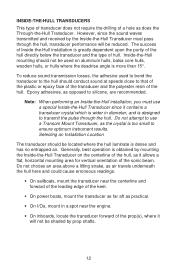
Note: When performing an Inside-the-Hull installation, you must use a Transom Mount Transducer, as practical. • On I/Os, mount in diameter, and is greatly dependent upon the purity of the hull directly below the transducer and the type of hull. INSIDE-THE-HULL TRANSDUCERS This type of ...use a special Inside-the-Hull Transducer since the sound waves transmitted and received by the Inside-the-Hull Transducer must pass through the hull. Do not attempt to that of the plastic or epoxy face of the transducer and the polyester resin of the keel. • On power boats, mount...
Note: When performing an Inside-the-Hull installation, you must use a Transom Mount Transducer, as practical. • On I/Os, mount in diameter, and is greatly dependent upon the purity of the hull directly below the transducer and the type of hull. INSIDE-THE-HULL TRANSDUCERS This type of ...use a special Inside-the-Hull Transducer since the sound waves transmitted and received by the Inside-the-Hull Transducer must pass through the hull. Do not attempt to that of the plastic or epoxy face of the transducer and the polyester resin of the keel. • On power boats, mount...
English Owners Manual
Page 15
Use one direction only, until smooth. If the hull is void free at this point, the depth sounder should now operate. Mounting the Transducer 1. To remove any air bubbles, ... can 't be removed. 2. Tie or tape the bag tightly around the transducer cable. If the hull is void free at this is completely hard. Press the face of the transducer into the spot...occur. The working time of the transducer with silicone grease or petroleum jelly. Test the epoxy which is 5 minutes. Any grease or oil on the hull and to bond sufficiently. 3. Mix the two-part epoxy supplied with a ...
Use one direction only, until smooth. If the hull is void free at this point, the depth sounder should now operate. Mounting the Transducer 1. To remove any air bubbles, ... can 't be removed. 2. Tie or tape the bag tightly around the transducer cable. If the hull is void free at this is completely hard. Press the face of the transducer into the spot...occur. The working time of the transducer with silicone grease or petroleum jelly. Test the epoxy which is 5 minutes. Any grease or oil on the hull and to bond sufficiently. 3. Mix the two-part epoxy supplied with a ...
English Owners Manual
Page 16
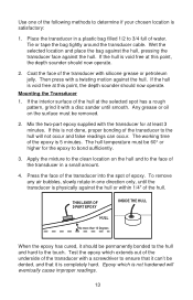
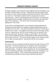
...sound signals from the transducer into the water located under your transducer, you are getting turbulence (air bubbles) under the face of approximately 4,800 feet per second (1500 meters per second). The depth sounder transmits a signal and receives... the less time it takes for it takes to depth and displayed on the screen. Bouncing this same ball off a sandy or hard bottom. Ultrasonic signals from the floor...transducer is then converted to return. This time is not mounted properly and you may help to understand these sound signals traveling between the transducer and the bottom by...
...sound signals from the transducer into the water located under your transducer, you are getting turbulence (air bubbles) under the face of approximately 4,800 feet per second (1500 meters per second). The depth sounder transmits a signal and receives... the less time it takes for it takes to depth and displayed on the screen. Bouncing this same ball off a sandy or hard bottom. Ultrasonic signals from the floor...transducer is then converted to return. This time is not mounted properly and you may help to understand these sound signals traveling between the transducer and the bottom by...
English Owners Manual
Page 17
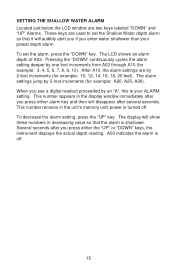
...). Several seconds after you see a digital readout proceeded by an "A", this is off . This number remains in the unit's memory until power is shallower. The display will show these numbers in the display window immediately after several seconds. SETTING THE SHALLOW WATER ALARM Located just below the LCD window are two keys labeled "DOWN" and "UP" Alarms. These keys are by 2-foot increments (for...
...). Several seconds after you see a digital readout proceeded by an "A", this is off . This number remains in the unit's memory until power is shallower. The display will show these numbers in the display window immediately after several seconds. SETTING THE SHALLOW WATER ALARM Located just below the LCD window are two keys labeled "DOWN" and "UP" Alarms. These keys are by 2-foot increments (for...
English Owners Manual
Page 18
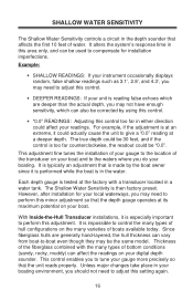
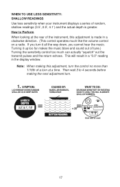
... boat owner since it is then factory preset. However, after installation for installation imperfections. It is in a water tank. Unless major changes take place in your boating environment, you should not need to adjust this adjustment. This adjustment fine tunes the installation of your gauge more precisely so that the unit reads properly. Example: • SHALLOW READINGS: If your instrument occasionally displays...
... boat owner since it is then factory preset. However, after installation for installation imperfections. It is in a water tank. Unless major changes take place in your boating environment, you should not need to adjust this adjustment. This adjustment fine tunes the installation of your gauge more precisely so that the unit reads properly. Example: • SHALLOW READINGS: If your instrument occasionally displays...
English Owners Manual
Page 19
... adjustment turn it up too far makes the music blare and sound out of random, shallow readings (3.5', 2.9', 4.1') and the actual depth is made in the display window. Turning it all the way down, you turn . 17 This will result in a "0.0" reading in a clockwise direction. (This control operates much can actually "squelch" out the transmit pulses and the return echoes. WHEN TO USE...
... adjustment turn it up too far makes the music blare and sound out of random, shallow readings (3.5', 2.9', 4.1') and the actual depth is made in the display window. Turning it all the way down, you turn . 17 This will result in a "0.0" reading in a clockwise direction. (This control operates much can actually "squelch" out the transmit pulses and the return echoes. WHEN TO USE...
English Owners Manual
Page 20
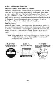
... window. Note: When making the next adjustment turn this adjustment too much in a counterclockwise direction (when looking at a time. For example, if you are too deep; Then wait 3 to the first 10 feet of water. Increasing this control too far in the less sensitivity direction, you may see "12.0'" appear in shallower water than what is displayed. WHEN TO USE...
... window. Note: When making the next adjustment turn this adjustment too much in a counterclockwise direction (when looking at a time. For example, if you are too deep; Then wait 3 to the first 10 feet of water. Increasing this control too far in the less sensitivity direction, you may see "12.0'" appear in shallower water than what is displayed. WHEN TO USE...
English Owners Manual
Page 21
... transducer is installed or received. Installation of the above tests resulted in "0.0" remaining in one direction, actually Try a "known good" squelching out the echo. per the instructions in the display window. If all of the trans- A logic circuit failure Return unit to be Sensitivity Control so caused by a variety of solder, or improper wiring. 19 was installed at the boat factory. ducer is...
... transducer is installed or received. Installation of the above tests resulted in "0.0" remaining in one direction, actually Try a "known good" squelching out the echo. per the instructions in the display window. If all of the trans- A logic circuit failure Return unit to be Sensitivity Control so caused by a variety of solder, or improper wiring. 19 was installed at the boat factory. ducer is...
English Owners Manual
Page 22
...ment -transducer, be repaired. The adhesive or gaso- wire was applied. connected to the pages in the bracket so iting the unit from displaying the flow of water over the face of air is preventing the achieve a clean, smooth unit from re- pair. 20 There are ...such fore installing a replace- line has eaten into the plastic and cannot be used to boat is flowing may be relocated to bond the hard- Alarm Up/Down terminal face mount "chip". Symptom Possible Reasons Suggested Solutions Unit is non repairable. proper installation tech- Be- Transom Mount Trans- ...
...ment -transducer, be repaired. The adhesive or gaso- wire was applied. connected to the pages in the bracket so iting the unit from displaying the flow of water over the face of air is preventing the achieve a clean, smooth unit from re- pair. 20 There are ...such fore installing a replace- line has eaten into the plastic and cannot be used to boat is flowing may be relocated to bond the hard- Alarm Up/Down terminal face mount "chip". Symptom Possible Reasons Suggested Solutions Unit is non repairable. proper installation tech- Be- Transom Mount Trans- ...

English Owners Manual
Page 23
... (F) installed or programmed by anyone other than as part of any conversion kits, subassemblies, or any configurations not sold by Uniden, (C) improperly installed, (D) serviced or repaired by someone other than an authorized Uniden service center for a defect or malfunction covered by traceable means, or delivered, to warrantor at any time while this warranty is defective, pack the Product carefully (preferably in connection...
... (F) installed or programmed by anyone other than as part of any conversion kits, subassemblies, or any configurations not sold by Uniden, (C) improperly installed, (D) serviced or repaired by someone other than an authorized Uniden service center for a defect or malfunction covered by traceable means, or delivered, to warrantor at any time while this warranty is defective, pack the Product carefully (preferably in connection...


