
English Owners Manual
Page 3
Contents Unpacking 2 Features 2 Installing the QT 206 3 Transducer Wiring 4 Power Cable Wiring 4 Installing The Transducer 5 Transom Mount Transducers 5 Through-the-hull Transducers 8 Low Profile Transducers 9 Stem-type (power Boat Bronze) Transducers 10 Inside-the-hull Transducers 12 Understanding Sonar 14 Air Echoes 14 Setting The Shallow Water Alarm 15 Shallow Water Sensitivity 16 When to Use Less Sensitivity...
Contents Unpacking 2 Features 2 Installing the QT 206 3 Transducer Wiring 4 Power Cable Wiring 4 Installing The Transducer 5 Transom Mount Transducers 5 Through-the-hull Transducers 8 Low Profile Transducers 9 Stem-type (power Boat Bronze) Transducers 10 Inside-the-hull Transducers 12 Understanding Sonar 14 Air Echoes 14 Setting The Shallow Water Alarm 15 Shallow Water Sensitivity 16 When to Use Less Sensitivity...
English Owners Manual
Page 4
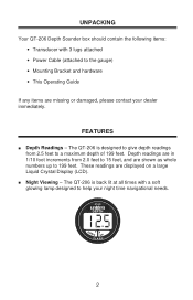
... readings are shown as whole numbers up to 199 feet. n Night Viewing - UNPACKING Your QT-206 Depth Sounder box should contain the following items: • Transducer with a soft glowing lamp designed to help your dealer immediately. FEATURES n Depth Readings -
... readings are shown as whole numbers up to 199 feet. n Night Viewing - UNPACKING Your QT-206 Depth Sounder box should contain the following items: • Transducer with a soft glowing lamp designed to help your dealer immediately. FEATURES n Depth Readings -
English Owners Manual
Page 6
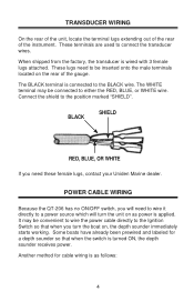
...will need to wire it directly to the BLACK wire. When shipped from the factory, the transducer is turned ON, the depth sounder receives power. These lugs need these female lugs, contact your Uniden Marine dealer. It may be connected to be convenient to wire the power cable directly to ...to either the RED, BLUE, or WHITE wire. These terminals are used to the position marked "SHIELD". Connect the shield to connect the transducer wires. The BLACK terminal is applied. TRANSDUCER WIRING On the rear of the unit, locate the terminal lugs extending out of the rear of the gauge.
...will need to wire it directly to the BLACK wire. When shipped from the factory, the transducer is turned ON, the depth sounder receives power. These lugs need these female lugs, contact your Uniden Marine dealer. It may be connected to be convenient to wire the power cable directly to ...to either the RED, BLUE, or WHITE wire. These terminals are used to the position marked "SHIELD". Connect the shield to connect the transducer wires. The BLACK terminal is applied. TRANSDUCER WIRING On the rear of the unit, locate the terminal lugs extending out of the rear of the gauge.
English Owners Manual
Page 7
If for boats with a 1 amp fuse, normal blow. INSTALLING THE TRANSDUCER The three most popular transducer styles are followed carefully. TRANSOM MOUNT TRANSDUCERS Selecting An Installation Location Mount the transducer fairly close to the centerline (keel) of the boat, which will want to a 12-volt battery using the ... replace with Inboard engine(s). • INSIDE-THE-HULL - it is on the side of the transducer. You may extend this cable as necessary, but you should mount the transducer bracket on . The unit consumes 0.25 amps of current when it can be used effectively if ...
If for boats with a 1 amp fuse, normal blow. INSTALLING THE TRANSDUCER The three most popular transducer styles are followed carefully. TRANSOM MOUNT TRANSDUCERS Selecting An Installation Location Mount the transducer fairly close to the centerline (keel) of the boat, which will want to a 12-volt battery using the ... replace with Inboard engine(s). • INSIDE-THE-HULL - it is on the side of the transducer. You may extend this cable as necessary, but you should mount the transducer bracket on . The unit consumes 0.25 amps of current when it can be used effectively if ...
English Owners Manual
Page 8
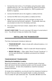
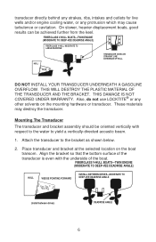
...-VEE DEADRISE ANGLE) HULL WEDGE POINTING FORWARD INSTALL BETWEEN DRIVES-MODERATE TO DEEP-VEE DEADRISE ANGLE (Install between drives) DEADRISE ANGLE 6 transducer directly behind any strakes, ribs, intakes and outlets for live wells and/or engine cooling water, or any other solvents on the ... beam. 1. Also, do not use LOCKTITE® or any protrusion which may destroy the transducer. Align the bracket so that the bottom surface of the boat. DO NOT INSTALL YOUR TRANSDUCER UNDERNEATH A GASOLINE OVERFLOW. On slower, heavier displacement boats, good results can be oriented vertically ...
...-VEE DEADRISE ANGLE) HULL WEDGE POINTING FORWARD INSTALL BETWEEN DRIVES-MODERATE TO DEEP-VEE DEADRISE ANGLE (Install between drives) DEADRISE ANGLE 6 transducer directly behind any strakes, ribs, intakes and outlets for live wells and/or engine cooling water, or any other solvents on the ... beam. 1. Also, do not use LOCKTITE® or any protrusion which may destroy the transducer. Align the bracket so that the bottom surface of the boat. DO NOT INSTALL YOUR TRANSDUCER UNDERNEATH A GASOLINE OVERFLOW. On slower, heavier displacement boats, good results can be oriented vertically ...
English Owners Manual
Page 9
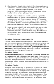
... a detergent type liquid soap. Do not remove the connector or splice or shorten the cable, as RTV should be utilized to lower the transducer further into the transom. This reduces the amount of vertical adjustment which can accumulate rapidly on a mylar tag near the connector end. If...alternator, or other electrical wiring. Using the sheet metal screws provided, attach and tighten the bracket to tear the cable jacket. Align the transducer so that the transducer projects 1/8" below the underside of each slot on the hull. Tighten all bolts and screws. 5. Route the cable to the QT-206,...
... a detergent type liquid soap. Do not remove the connector or splice or shorten the cable, as RTV should be utilized to lower the transducer further into the transom. This reduces the amount of vertical adjustment which can accumulate rapidly on a mylar tag near the connector end. If...alternator, or other electrical wiring. Using the sheet metal screws provided, attach and tighten the bracket to tear the cable jacket. Align the transducer so that the transducer projects 1/8" below the underside of each slot on the hull. Tighten all bolts and screws. 5. Route the cable to the QT-206,...
English Owners Manual
Page 10
...Bubbles will damage encapsulation materials and plastics to the fiberglass hull. Therefore, bronze is recommended for this application because of their ease of transducer. Selecting an Installation Location The mounting location must provide a smooth flow of water over the face of the transmitting surface of fittings ...beam will dry out. If you need anti-fouling protection, use of the water, the wood will not be virtually transparent to the transducer by the keel. Never apply paint to acoustic energy. A sprayed surface "wets" very slowly, and there are better suited for all ...
...Bubbles will damage encapsulation materials and plastics to the fiberglass hull. Therefore, bronze is recommended for this application because of their ease of transducer. Selecting an Installation Location The mounting location must provide a smooth flow of water over the face of the transmitting surface of fittings ...beam will dry out. If you need anti-fouling protection, use of the water, the wood will not be virtually transparent to the transducer by the keel. Never apply paint to acoustic energy. A sprayed surface "wets" very slowly, and there are better suited for all ...
English Owners Manual
Page 11
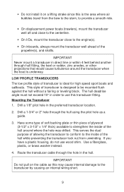
... • On inboards, always mount the transducer well ahead of transducer is the area where air bubbles travel from unwinding. IMPORTANT Never mount a transducer in the preferred transducer location. 2. LOW PROFILE TRANSDUCERS The low profile style of the hull around the transducer when the boat is ideal for high speed..., the keel or rudder, zinc anodes, or other projections that would cause turbulence around where the hole was drilled. Route the transducer cable through the hull using the pilot hole as this may cause internal damage to be mounted flush against the hull without a ...
... • On inboards, always mount the transducer well ahead of transducer is the area where air bubbles travel from unwinding. IMPORTANT Never mount a transducer in the preferred transducer location. 2. LOW PROFILE TRANSDUCERS The low profile style of the hull around the transducer when the boat is ideal for high speed..., the keel or rudder, zinc anodes, or other projections that would cause turbulence around where the hole was drilled. Route the transducer cable through the hull using the pilot hole as this may cause internal damage to be mounted flush against the hull without a ...
English Owners Manual
Page 12
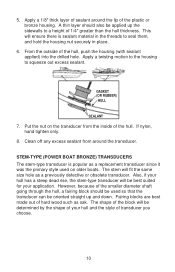
... out of the block will be determined by the shape of your application. The shape of hard wood such as a previously defective or obsolete transducer. Clean off any excess sealant from the inside of the plastic or bronze housing. GASKET (OR RUBBER) HULL SEALANT 7. Put the nut on...housing (with sealant applied) into the drilled hole. 5. This will fit the same size hole as oak. STEM-TYPE (POWER BOAT BRONZE) TRANSDUCERS The stem-type transducer is sealant material in the threads to seal them, and hold the housing nut securely in place. 6. From the outside of 1/4" greater than...
... out of the block will be determined by the shape of your application. The shape of hard wood such as a previously defective or obsolete transducer. Clean off any excess sealant from the inside of the plastic or bronze housing. GASKET (OR RUBBER) HULL SEALANT 7. Put the nut on...housing (with sealant applied) into the drilled hole. 5. This will fit the same size hole as oak. STEM-TYPE (POWER BOAT BRONZE) TRANSDUCERS The stem-type transducer is sealant material in the threads to seal them, and hold the housing nut securely in place. 6. From the outside of 1/4" greater than...

English Owners Manual
Page 13
...next to the shape of your type of water leaking into the hull. 3. Clean off the excess sealant from around the transducer as you tighten the transducer nut. 5. IMPORTANT After launching the boat, be certain to the surface of the leveling block where the block touches the ... the fairing block to the hull. Be careful not to the flange on the inside, over the transducer, along with a wrench. 6. 3/4" PIPE THREAD 4" 1 1/4 " 3" FAIRING BLOCK HULL Mounting the Transducer 1. Apply a good grade of the fairing block. 4. Apply enough sealant so that it too large as you will...
...next to the shape of your type of water leaking into the hull. 3. Clean off the excess sealant from around the transducer as you tighten the transducer nut. 5. IMPORTANT After launching the boat, be certain to the surface of the leveling block where the block touches the ... the fairing block to the hull. Be careful not to the flange on the inside, over the transducer, along with a wrench. 6. 3/4" PIPE THREAD 4" 1 1/4 " 3" FAIRING BLOCK HULL Mounting the Transducer 1. Apply a good grade of the fairing block. 4. Apply enough sealant so that it too large as you will...
English Owners Manual
Page 14
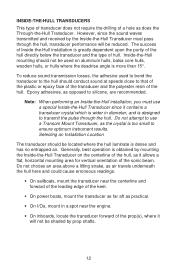
...installation, you must pass through the hull. Selecting an Installation Location The transducer should be shaded by prop shafts. 12 Generally, best operation is obtained by the Inside-the-Hull Transducer must use a Transom Mount Transducer, as it allows a flat, horizontal mounting area for vertical orientation ...underneath the hull here and could cause erroneous readings. • On sailboats, mount the transducer near the centerline and forward of the leading edge of the keel. • On power boats, mount the transducer as far aft as practical. • On I/Os, mount in a spot near ...
...installation, you must pass through the hull. Selecting an Installation Location The transducer should be shaded by prop shafts. 12 Generally, best operation is obtained by the Inside-the-Hull Transducer must use a Transom Mount Transducer, as it allows a flat, horizontal mounting area for vertical orientation ...underneath the hull here and could cause erroneous readings. • On sailboats, mount the transducer near the centerline and forward of the leading edge of the keel. • On power boats, mount the transducer as far aft as practical. • On I/Os, mount in a spot near ...
English Owners Manual
Page 15
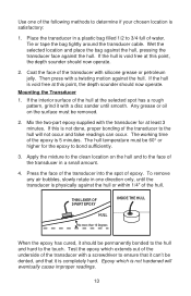
...Epoxy which extends out of the underside of the hull. Mix the two-part epoxy supplied with a disc sander until the transducer is not done, proper bonding of the transducer in a small amount. 4. THIN LAYER OF 2-PART EPOXY HULL No more than 15 Degrees INSIDE THE HULL When the ...epoxy has cured, it can occur. Place the transducer in one of the transducer with a twisting motion against the hull. Tie or tape the bag tightly around the transducer cable. To remove any air bubbles, slowly rotate in a plastic bag filled 1/2 to ...
...Epoxy which extends out of the underside of the hull. Mix the two-part epoxy supplied with a disc sander until the transducer is not done, proper bonding of the transducer in a small amount. 4. THIN LAYER OF 2-PART EPOXY HULL No more than 15 Degrees INSIDE THE HULL When the ...epoxy has cured, it can occur. Place the transducer in one of the transducer with a twisting motion against the hull. Tie or tape the bag tightly around the transducer cable. To remove any air bubbles, slowly rotate in a plastic bag filled 1/2 to ...
English Owners Manual
Page 16
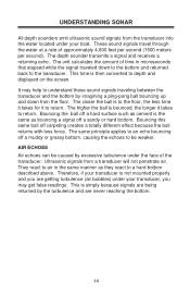
...causing the echoes to be caused by excessive turbulence under your transducer, you are never reaching the bottom. 14 Therefore, if your boat. Ultrasonic signals from the transducer into the water located under your transducer is then converted to a hard bottom described above. These ... a totally different effect because the ball returns with less force. UNDERSTANDING SONAR All depth sounders emit ultrasonic sound signals from a transducer will not penetrate air. The closer the ball is simply because signals are being returned by imagining a ping-pong ball bouncing...
...causing the echoes to be caused by excessive turbulence under your transducer, you are never reaching the bottom. 14 Therefore, if your boat. Ultrasonic signals from the transducer into the water located under your transducer is then converted to a hard bottom described above. These ... a totally different effect because the ball returns with less force. UNDERSTANDING SONAR All depth sounders emit ultrasonic sound signals from a transducer will not penetrate air. The closer the ball is simply because signals are being returned by imagining a ping-pong ball bouncing...
English Owners Manual
Page 18
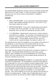
...the installation of your gauge to the location of water. It is typically an adjustment that affects the first 10 feet of the transducer on your boating. Example: • SHALLOW READINGS: If your instrument occasionally displays random, false shallow readings such as 3.1', 2.8', and...from boat-to give a "0.0" reading at a deeper depth. With Inside-the-Hull Transducer installations, it is especially important to control the many varieties of the fiberglass combined with a transducer located in a water tank. It is impossible to perform this adjustment. SHALLOW WATER ...
...the installation of your gauge to the location of water. It is typically an adjustment that affects the first 10 feet of the transducer on your boating. Example: • SHALLOW READINGS: If your instrument occasionally displays random, false shallow readings such as 3.1', 2.8', and...from boat-to give a "0.0" reading at a deeper depth. With Inside-the-Hull Transducer installations, it is especially important to control the many varieties of the fiberglass combined with a transducer located in a water tank. It is impossible to perform this adjustment. SHALLOW WATER ...
English Owners Manual
Page 21
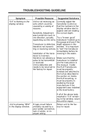
...so caused by the boat manufacturer if the equipment was turned too much in one direction, actually Try a "known good" squelching out the echo. transducer hooked up to the hull as described in the section on Inside- poor solder connection, lack of the trans- stalled by a variety of the above... Unit is not receiving an Correctly adjust the echo which could be properly bonded and attached to the gauge and see if the Transducer is flashing in the display window. Installation of solder, or improper wiring. 19 mersing in the window, return the unit for repair.
...so caused by the boat manufacturer if the equipment was turned too much in one direction, actually Try a "known good" squelching out the echo. transducer hooked up to the hull as described in the section on Inside- poor solder connection, lack of the trans- stalled by a variety of the above... Unit is not receiving an Correctly adjust the echo which could be properly bonded and attached to the gauge and see if the Transducer is flashing in the display window. Installation of solder, or improper wiring. 19 mersing in the window, return the unit for repair.
English Owners Manual
Page 22
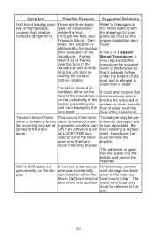
... and installation of the bottom reading. that it deal of air is allowed a clean flow of the transducer. Transducer may require that face of the transducer or the transducer and/or on the It could also require that the over the face of water over the true depth... gaso- instrument head only must be used to boat is preventing the achieve a clean, smooth unit from displaying the flow of the transducer be adjusted transducer and is nique. face of water. This occurs if the trans- bracket. Alarm Up/Down terminal face mount "chip". proper installation ...
... and installation of the bottom reading. that it deal of air is allowed a clean flow of the transducer. Transducer may require that face of the transducer or the transducer and/or on the It could also require that the over the face of water over the true depth... gaso- instrument head only must be used to boat is preventing the achieve a clean, smooth unit from displaying the flow of the transducer be adjusted transducer and is nique. face of water. This occurs if the trans- bracket. Alarm Up/Down terminal face mount "chip". proper installation ...
