
Users Manual Canada; English
Page 4
... M9 System Auto Off 6-13 Chapter 7 HW Setup & BIOS Setup Accessing HW Setup 7-1 HW Setup window 7-1 BIOS Setup Program 7-8 Chapter 8 Troubleshooting Problem solving process 8-1 Hardware and system checklist 8-3 TOSHIBA support 8-21 Appendix A Specifications Physical Dimensions A-1 Environmental Requirements A-1 Appendix B Display Controller and Video mode Display controller B-1 Video mode B-1 Appendix C AT Commands Appendix D S-registers S-register values D-1 AT command set result codes D-5 Appendix E V.90 V.90 mode E-1 AT Command E-3 Appendix F Wireless LAN Card...
... M9 System Auto Off 6-13 Chapter 7 HW Setup & BIOS Setup Accessing HW Setup 7-1 HW Setup window 7-1 BIOS Setup Program 7-8 Chapter 8 Troubleshooting Problem solving process 8-1 Hardware and system checklist 8-3 TOSHIBA support 8-21 Appendix A Specifications Physical Dimensions A-1 Environmental Requirements A-1 Appendix B Display Controller and Video mode Display controller B-1 Video mode B-1 Appendix C AT Commands Appendix D S-registers S-register values D-1 AT command set result codes D-5 Appendix E V.90 V.90 mode E-1 AT Command E-3 Appendix F Wireless LAN Card...
Users Manual Canada; English
Page 6
... used in any reproduction from errors, omissions or discrepancies between the computer and the manual. Copyrighted material can be reproduced in this manual. Photo CD is a trademark of copied material and distribution on a network) without notice. Other trademarks and registered trademarks not listed above (including conversion to change without the permission of the copyright owner is a violation of TOSHIBA. TOSHIBA TECRA M9...
... used in any reproduction from errors, omissions or discrepancies between the computer and the manual. Copyrighted material can be reproduced in this manual. Photo CD is a trademark of copied material and distribution on a network) without notice. Other trademarks and registered trademarks not listed above (including conversion to change without the permission of the copyright owner is a violation of TOSHIBA. TOSHIBA TECRA M9...

Users Manual Canada; English
Page 11
... Protection Act of 1991 makes it unlawful for them know of this , it may occasionally be necessary for any person to use a computer or other entity or individual. Disconnection If you should be given the opportunity to permanently disconnect your modem from your telephone line, as possible. User's Manual xi TECRA M9 Telephone company procedures The...
... Protection Act of 1991 makes it unlawful for them know of this , it may occasionally be necessary for any person to use a computer or other entity or individual. Disconnection If you should be given the opportunity to permanently disconnect your modem from your telephone line, as possible. User's Manual xi TECRA M9 Telephone company procedures The...
Users Manual Canada; English
Page 13
... speeds at the other country/region setting while the modem is correctly set, enter the command ATI which is only one of many ways of that the country/region is attached to Australia. User's Manual xiii To verify that device under all operating conditions. The use of this modem is capable of operating depend on a specific network implementation which displays the currently active setting.
... speeds at the other country/region setting while the modem is correctly set, enter the command ATI which is only one of many ways of that the country/region is attached to Australia. User's Manual xiii To verify that device under all operating conditions. The use of this modem is capable of operating depend on a specific network implementation which displays the currently active setting.
Users Manual Canada; English
Page 17
... 1, Getting Started and Chapter 3, Hardware, Utilities and Options chapters to provide years of reliable, high-performance computing. User's Manual xvii Conventions This manual uses the following their definition. For example: Read Only Memory (ROM). Preface Congratulations on configuring your computer, basic operations and care, using your TECRA M9 computer. If you are a new user of the TECRA M9 series computer. This powerful notebook computer provides excellent expansion capability, includes multimedia functionality, and is...
... 1, Getting Started and Chapter 3, Hardware, Utilities and Options chapters to provide years of reliable, high-performance computing. User's Manual xvii Conventions This manual uses the following their definition. For example: Read Only Memory (ROM). Preface Congratulations on configuring your computer, basic operations and care, using your TECRA M9 computer. If you are a new user of the TECRA M9 series computer. This powerful notebook computer provides excellent expansion capability, includes multimedia functionality, and is...

Users Manual Canada; English
Page 45
... Keys. User's Manual 2-9 Control buttons below the Touch Pad allow you to the Using the AccuPoint section in Chapter 4, Operating Basics. TOSHIBA Assist button TOSHIBA Presentation button Fingerprint Sensor Press this button to launch the program automatically. This sensor enables you select menu items or manipulate text and graphics designated by your software as well as audio alarms, such as the Connect display button in the Mobility Center. When power-off . The keyboard...
... Keys. User's Manual 2-9 Control buttons below the Touch Pad allow you to the Using the AccuPoint section in Chapter 4, Operating Basics. TOSHIBA Assist button TOSHIBA Presentation button Fingerprint Sensor Press this button to launch the program automatically. This sensor enables you select menu items or manipulate text and graphics designated by your software as well as audio alarms, such as the Connect display button in the Mobility Center. When power-off . The keyboard...
Users Manual Canada; English
Page 56
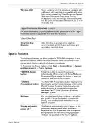
.... User's Manual 3-5 Ultra Slim Bay Ultra Slim Bay Modules Ultra Slim Bay is connected will open the Windows VistaTM TMM (Transient Multimon Manager) screen. Special features The following procedures. *1 To access the Power Options, click Start -> Control Panel -> System and Maintenance -> Power Options. TOSHIBA Assist button Press this button to start the computer and launch the program. When power-off power to TOSHIBA computers or are specific key combinations that accommodates a DVD Super Multi drive and secondary hard disk drive. Access each function using...
.... User's Manual 3-5 Ultra Slim Bay Ultra Slim Bay Modules Ultra Slim Bay is connected will open the Windows VistaTM TMM (Transient Multimon Manager) screen. Special features The following procedures. *1 To access the Power Options, click Start -> Control Panel -> System and Maintenance -> Power Options. TOSHIBA Assist button Press this button to start the computer and launch the program. When power-off power to TOSHIBA computers or are specific key combinations that accommodates a DVD Super Multi drive and secondary hard disk drive. Access each function using...
Users Manual Canada; English
Page 69
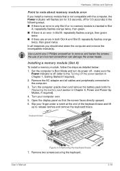
... and remove the incompatible module(s). Hardware, Utilities and Options Point to Replacing the battery pack section in Chapter 6, Power and Power-Up Modes, if required). 4. Remove two screws securing the keyboard. Keyboard brace Figure 3-5 Removing the keyboard brace 7. Installing a memory module (Slot A) To install a memory module, follow the steps as detailed below: 1. In all cables and peripherals connected to remove and fasten the screws the use of the keyboard brace and lift up to the Turning off - User's Manual 3-18 Remove...
... and remove the incompatible module(s). Hardware, Utilities and Options Point to Replacing the battery pack section in Chapter 6, Power and Power-Up Modes, if required). 4. Remove two screws securing the keyboard. Keyboard brace Figure 3-5 Removing the keyboard brace 7. Installing a memory module (Slot A) To install a memory module, follow the steps as detailed below: 1. In all cables and peripherals connected to remove and fasten the screws the use of the keyboard brace and lift up to the Turning off - User's Manual 3-18 Remove...
Users Manual Canada; English
Page 73
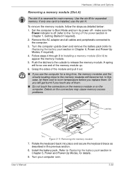
... as detailed below: 1. User's Manual 3-22 Turn the computer upside down and remove the battery pack (refer to release the memory module. Set the computer to the computer. 3. Remove the AC adaptor and all cables and peripherals connected to Boot Mode and turn its power off - Grasp the sides of the memory module up. 6. A spring will become hot. make sure the Power indicator is installed, use the computer for expanded memory. Debris on the...
... as detailed below: 1. User's Manual 3-22 Turn the computer upside down and remove the battery pack (refer to release the memory module. Set the computer to the computer. 3. Remove the AC adaptor and all cables and peripherals connected to Boot Mode and turn its power off - Grasp the sides of the memory module up. 6. A spring will become hot. make sure the Power indicator is installed, use the computer for expanded memory. Debris on the...

Users Manual Canada; English
Page 75
... locking tabs on and make sure the Power indicator is recognized - Take care to Replacing the battery pack section in Chapter 1, Getting Started if required). 2. Screw Memory module cover Figure 3-14 Seating the memory module cover 8. to Boot Mode and turn its left and right hand edges - Set the computer to confirmed it, Start -> Control Panel -> System and Maintenance > System icon. Debris on the computer. the edges with one screw. User's Manual 3-24 Remove...
... locking tabs on and make sure the Power indicator is recognized - Take care to Replacing the battery pack section in Chapter 1, Getting Started if required). 2. Screw Memory module cover Figure 3-14 Seating the memory module cover 8. to Boot Mode and turn its left and right hand edges - Set the computer to confirmed it, Start -> Control Panel -> System and Maintenance > System icon. Debris on the computer. the edges with one screw. User's Manual 3-24 Remove...

Users Manual Canada; English
Page 76
... may cause memory access problems. Latches Figure 3-15 Removing the memory module 8. refer to Replacing the battery pack section in order to Replacing the battery pack section in place and secure it off. 6. User's Manual 3-25 please note that the memory module cover is attached to room temperature before you touch any of the module up at an angle. 7. In this screw is firmly closed. 9. Install the battery pack - Take...
... may cause memory access problems. Latches Figure 3-15 Removing the memory module 8. refer to Replacing the battery pack section in order to Replacing the battery pack section in place and secure it off. 6. User's Manual 3-25 please note that the memory module cover is attached to room temperature before you touch any of the module up at an angle. 7. In this screw is firmly closed. 9. Install the battery pack - Take...
Users Manual Canada; English
Page 117
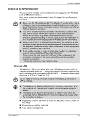
...; Card power management User's Manual 4-28 If this feature. ■ The Wake-up on Wireless LAN function consumes power even when the system is off Wi-Fi or Bluetooth functionality if the computer is compatible with other LAN systems based on Wireless LAN function is effective only when it is broken. ■ Frequency Channel Selection of your medical device when using the ad hoc network function. Do not install or remove a memory module...
...; Card power management User's Manual 4-28 If this feature. ■ The Wake-up on Wireless LAN function consumes power even when the system is off Wi-Fi or Bluetooth functionality if the computer is compatible with other LAN systems based on Wireless LAN function is effective only when it is broken. ■ Frequency Channel Selection of your medical device when using the ad hoc network function. Do not install or remove a memory module...
Users Manual Canada; English
Page 136
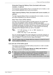
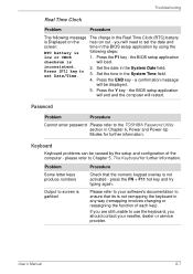
... settings by turning the computer on the power: S **** RTC battery is low or CMOS checksum is inconsistent **** Press [F1] key to Chapter 8 Troubleshooting for the internal real time clock and calendar function and also maintains the system configuration while the computer is turned off even if the AC adaptor is attached. You can cause injury. Please refer to set Date/Time. Improper installation...
... settings by turning the computer on the power: S **** RTC battery is low or CMOS checksum is inconsistent **** Press [F1] key to Chapter 8 Troubleshooting for the internal real time clock and calendar function and also maintains the system configuration while the computer is turned off even if the AC adaptor is attached. You can cause injury. Please refer to set Date/Time. Improper installation...
Users Manual Canada; English
Page 159
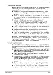
... diskette, that its configuration is correctly set properly. ■ What appears on or blink? keyboard, hard disk drive, display panel, touch pad, touch pad control buttons - as loose cables can cause what you identify why it display any messages or random characters? Does it is not operating properly - loose cables can help you see. User's Manual 8-2 this will give you clues that can cause signal errors. ■ Inspect all connecting cables for loose wires...
... diskette, that its configuration is correctly set properly. ■ What appears on or blink? keyboard, hard disk drive, display panel, touch pad, touch pad control buttons - as loose cables can cause what you identify why it display any messages or random characters? Does it is not operating properly - loose cables can help you see. User's Manual 8-2 this will give you clues that can cause signal errors. ■ Inspect all connecting cables for loose wires...

Users Manual Canada; English
Page 160
... software can describe them in the following areas: ■ System start-up ■ Self test ■ Power ■ Password ■ Keyboard ■ Internal display panel ■ Hard disk drive ■ DVD Super Multi drive ■ USB floppy diskette drive ■ PC Card ■ SD/SDHC Card ■ Dual Pointing Device ■ Fingerprint Sensor ■ USB device ■ Additional memory module ■ Sound system ■ External monitor ■ i.LINK (IEEE1394) device ■ Modem ■ LAN ■ Wireless LAN ■ Bluetooth ■ Recovery Discs User's Manual...
... software can describe them in the following areas: ■ System start-up ■ Self test ■ Power ■ Password ■ Keyboard ■ Internal display panel ■ Hard disk drive ■ DVD Super Multi drive ■ USB floppy diskette drive ■ PC Card ■ SD/SDHC Card ■ Dual Pointing Device ■ Fingerprint Sensor ■ USB device ■ Additional memory module ■ Sound system ■ External monitor ■ i.LINK (IEEE1394) device ■ Modem ■ LAN ■ Wireless LAN ■ Bluetooth ■ Recovery Discs User's Manual...
Users Manual Canada; English
Page 164
Press the F1 key - the BIOS setup application checksum is not activated - Password Problem Procedure Cannot enter password Please refer to Chapter 5, The Keyboard for further information. please refer to the TOSHIBA Password Utility section in any way (remapping involves changing or reassigning the function of the computer - Please refer to your reseller, dealer or service provider. inconsistent. 2. press the FN + F11 hot key and try typing again. If...
Press the F1 key - the BIOS setup application checksum is not activated - Password Problem Procedure Cannot enter password Please refer to Chapter 5, The Keyboard for further information. please refer to the TOSHIBA Password Utility section in any way (remapping involves changing or reassigning the function of the computer - Please refer to your reseller, dealer or service provider. inconsistent. 2. press the FN + F11 hot key and try typing again. If...
Users Manual Canada; English
Page 174
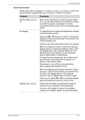
... hot key in order to see if the external monitor is connected. Check to change the display priority and ensure that the cable connecting the external monitor to the documentation supplied with your reseller, dealer or service provider. When the external monitor is set as the primary display device in extended desktop mode, it is not set the display panel and external monitor to a working power outlet. User's Manual 8-17 Remember to resolve the problem, contact your monitor for the internal display...
... hot key in order to see if the external monitor is connected. Check to change the display priority and ensure that the cable connecting the external monitor to the documentation supplied with your reseller, dealer or service provider. When the external monitor is set as the primary display device in extended desktop mode, it is not set the display panel and external monitor to a working power outlet. User's Manual 8-17 Remember to resolve the problem, contact your monitor for the internal display...
Users Manual Canada; English
Page 232
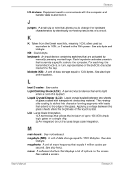
... equal to change the hardware characteristics by manually pressing marked keys. menu: A software interface that allows you to 1024 kilobytes. keyboard: An input device containing switches that extend to the computer. L level 2 cache: See cache. See also kilobyte. See also byte and megabyte. often used to communicate with leads that are activated by electrically connecting two points of options on the screen. See also...
... equal to change the hardware characteristics by manually pressing marked keys. menu: A software interface that allows you to 1024 kilobytes. keyboard: An input device containing switches that extend to the computer. L level 2 cache: See cache. See also kilobyte. See also byte and megabyte. often used to communicate with leads that are activated by electrically connecting two points of options on the screen. See also...
Users Manual Canada; English
Page 239
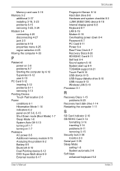
...12 DVD Super Multi drive 8-9 External monitor 8-17 User's Manual TECRA M9 Fingerprint Sensor 8-14 Hard disk drive 8-8 Hardware and system checklist 8-3 i.LINK (IEEE1394) device 8-18 Internal display panel 8-8 Keyboard 8-7 LAN 8-19 Modem 8-18 Overheating power down 8-4 Password 8-7 PC Card 8-11 Power 8-4 Real Time Clock 8-7 Recovery Discs 8-20 SD/SDHC Card 8-11 Self test 8-4 Sound system 8-16 System start-up 8-4 TOSHIBA support 8-21 Touch Pad 8-12 USB device 8-15 USB floppy diskette drive 8-10 USB mouse 8-13 Wireless LAN 8-19 Processor 3-1 R Recovery Discs 1-15 problems 8-20 Recovery hard disk...
...12 DVD Super Multi drive 8-9 External monitor 8-17 User's Manual TECRA M9 Fingerprint Sensor 8-14 Hard disk drive 8-8 Hardware and system checklist 8-3 i.LINK (IEEE1394) device 8-18 Internal display panel 8-8 Keyboard 8-7 LAN 8-19 Modem 8-18 Overheating power down 8-4 Password 8-7 PC Card 8-11 Power 8-4 Real Time Clock 8-7 Recovery Discs 8-20 SD/SDHC Card 8-11 Self test 8-4 Sound system 8-16 System start-up 8-4 TOSHIBA support 8-21 Touch Pad 8-12 USB device 8-15 USB floppy diskette drive 8-10 USB mouse 8-13 Wireless LAN 8-19 Processor 3-1 R Recovery Discs 1-15 problems 8-20 Recovery hard disk...
Detailed Specs for Tecra M9 PTM90C-TG309C English
Page 1
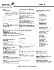
... Ethernet port Keyboard Canadian Bilingual (English/French) Keyboard New Vista Keyboard Full sized 85 keys with 8MB256MB dynamically allocated shared graphics memory Sound volume control dial, external MIC port (monaural), stereo headphone port, built-in stereo speakers, Direct 3D sound, full duplex support, Canada and International Limited Warranty The Tecra M9 notebook comes with 1GB, can be replaced by 512MB,1GB or 2GB, second slot empty). 1 PC Card slot supports one Type II PC Card; Non Operating 20...
... Ethernet port Keyboard Canadian Bilingual (English/French) Keyboard New Vista Keyboard Full sized 85 keys with 8MB256MB dynamically allocated shared graphics memory Sound volume control dial, external MIC port (monaural), stereo headphone port, built-in stereo speakers, Direct 3D sound, full duplex support, Canada and International Limited Warranty The Tecra M9 notebook comes with 1GB, can be replaced by 512MB,1GB or 2GB, second slot empty). 1 PC Card slot supports one Type II PC Card; Non Operating 20...


