

Maintenance Manual
Page 4
Appendices The appendices describe the following parts: Chapter 1 Hardware Overview describes the T PORTÉGÉ R500. system unit and each FRU. Chapter 4 Replacement Procedures describes the removal and replacement of the FRUs. Chapter 2 Troubleshooting ...for maintenance service. The manual is divided into the following : ‰ Handling the LCD module ‰ Board layout ‰ Pin assignments ‰ Keyboard scan/character codes ‰ Key layout ‰ Wiring diagrams ‰ BIOS rewrite procedures ‰ EC/KBC rewrite procedures ‰ Reliability iv [CONFIDENTIAL]...
Appendices The appendices describe the following parts: Chapter 1 Hardware Overview describes the T PORTÉGÉ R500. system unit and each FRU. Chapter 4 Replacement Procedures describes the removal and replacement of the FRUs. Chapter 2 Troubleshooting ...for maintenance service. The manual is divided into the following : ‰ Handling the LCD module ‰ Board layout ‰ Pin assignments ‰ Keyboard scan/character codes ‰ Key layout ‰ Wiring diagrams ‰ BIOS rewrite procedures ‰ EC/KBC rewrite procedures ‰ Reliability iv [CONFIDENTIAL]...

Maintenance Manual
Page 5
... example, Ctrl + Pause (Break) means you must hold down Ctrl and at the same time press the third. User input Text that appears on the keyboard is shown in the boldface type below : Format complete System transferred PORTÉGÉ R400 Maintenance Manual (960-623))[CONFIDENTIAL] v Acronyms On the first appearance...
... example, Ctrl + Pause (Break) means you must hold down Ctrl and at the same time press the third. User input Text that appears on the keyboard is shown in the boldface type below : Format complete System transferred PORTÉGÉ R400 Maintenance Manual (960-623))[CONFIDENTIAL] v Acronyms On the first appearance...

Maintenance Manual
Page 6
... 1.4 2.5-inch Hard Disk Drive 1-14 1.5 1.8-inch Hard Disk Drive 1-15 1.6 DVD-Super Multi Drive Optical Drive (ODD 1-16 1.7 Keyboard...1- 17 1.8 TFT Color Display 1- 18 1.9 Power Supply ...1- 19 1.10 Batteries ...1- 22 1.11 AC Adaptor...1- 25 Chapter 2 Troubleshooting ...Flowchart 2-2 2.3 Power Supply Troubleshooting 2-6 2.4 System Board Troubleshooting 2-15 2.5 USB FDD Troubleshooting 2-31 2.6 HDD Troubleshooting 2-35 2.7 Keyboard and Dual point Troubleshooting 2-40 2.8 Display Troubleshooting 2-42 2.9 Optical Drive Troubleshooting 2-44 2.10 LAN Troubleshooting 2-46 2.11 Bluetooth ...
... 1.4 2.5-inch Hard Disk Drive 1-14 1.5 1.8-inch Hard Disk Drive 1-15 1.6 DVD-Super Multi Drive Optical Drive (ODD 1-16 1.7 Keyboard...1- 17 1.8 TFT Color Display 1- 18 1.9 Power Supply ...1- 19 1.10 Batteries ...1- 22 1.11 AC Adaptor...1- 25 Chapter 2 Troubleshooting ...Flowchart 2-2 2.3 Power Supply Troubleshooting 2-6 2.4 System Board Troubleshooting 2-15 2.5 USB FDD Troubleshooting 2-31 2.6 HDD Troubleshooting 2-35 2.7 Keyboard and Dual point Troubleshooting 2-40 2.8 Display Troubleshooting 2-42 2.9 Optical Drive Troubleshooting 2-44 2.10 LAN Troubleshooting 2-46 2.11 Bluetooth ...
Maintenance Manual
Page 7
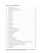
... Diagnostics 3.1 The Diagnostic Test 3-1 3.2 Executing the Diagnostic Test 3-4 3.3 Setting of the hardware configuration 3-9 3.4 Heatrun Test...3-11 3.5 Subtest Names...3-12 3.6 System Test...3-14 3.7 Memory Test...3-16 3.8 Keyboard Test...3-17 3.9 Display Test ...3-18 3.10 Floppy Disk Test...3-21 3.11 Printer Test...3-23 3.12 Async Test ...3-25 3.13 Hard Disk Test ...3-26 3.14 Real...
... Diagnostics 3.1 The Diagnostic Test 3-1 3.2 Executing the Diagnostic Test 3-4 3.3 Setting of the hardware configuration 3-9 3.4 Heatrun Test...3-11 3.5 Subtest Names...3-12 3.6 System Test...3-14 3.7 Memory Test...3-16 3.8 Keyboard Test...3-17 3.9 Display Test ...3-18 3.10 Floppy Disk Test...3-21 3.11 Printer Test...3-23 3.12 Async Test ...3-25 3.13 Hard Disk Test ...3-26 3.14 Real...
Maintenance Manual
Page 8
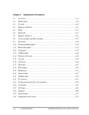
Chapter 4 Replacement Procedures 4.1 Overview...4-1 4.2 Battery pack ...4-8 4.3 PC card...4-10 4.4 Memory module B 4-11 4.5 HDD...4-13 4.6 Keyboard...4-17 4.7 Memory module A 4-21 4.8 Cover assembly and Base assembly 4-23 4.9 Base latch ...4-26 4.10 Front panel/Microphone 4-27 4.11 Bluetooth module...4-33 4.12 Touch pad...4-...
Chapter 4 Replacement Procedures 4.1 Overview...4-1 4.2 Battery pack ...4-8 4.3 PC card...4-10 4.4 Memory module B 4-11 4.5 HDD...4-13 4.6 Keyboard...4-17 4.7 Memory module A 4-21 4.8 Cover assembly and Base assembly 4-23 4.9 Base latch ...4-26 4.10 Front panel/Microphone 4-27 4.11 Bluetooth module...4-33 4.12 Touch pad...4-...

Maintenance Manual
Page 9
Appendices Appendix A Handling the LCD Module A-1 Appendix B Board Layout B-1 Appendix C Pin Assignments C-1 Appendix D Keyboard Scan/Character Codes D-1 Appendix E Key Layout...E-1 Appendix F Wiring Diagrams F-1 Appendix G BIOS rewrite Procedures G-1 Appendix H EC/KBC rewrite Procedures H-1 Appendix I Reliability...I-1 PORTÉGÉ R400 Maintenance Manual (960-623))[CONFIDENTIAL] ix
Appendices Appendix A Handling the LCD Module A-1 Appendix B Board Layout B-1 Appendix C Pin Assignments C-1 Appendix D Keyboard Scan/Character Codes D-1 Appendix E Key Layout...E-1 Appendix F Wiring Diagrams F-1 Appendix G BIOS rewrite Procedures G-1 Appendix H EC/KBC rewrite Procedures H-1 Appendix I Reliability...I-1 PORTÉGÉ R400 Maintenance Manual (960-623))[CONFIDENTIAL] ix

Maintenance Manual
Page 14
...Figure 1-8 Figure 1-8 Front of the computer 1- 6 System unit configuration 1- 7 System unit block diagram 1- 8 3.5-inch FDD (USB External 1- 13 2.5-inch HDD 1- 14 1.8-inch HDD 1- 15 Keyboard ...1- 17 LCD module 1- 18 Tables Table 1-1 Table 1-2 Table 1-3 Table 1-4 Table 1-5 Table 1-6 Table 1-7 Table 1-8 Table 1-9 Table 1-10 3.5-inch FDD specifications 1- 13 2.5-inch HDD specifications... 1- 22 Time required for charges 1- 23 RTC battery charging/data preservation time 1- 24 AC adapter specifications 1- 25 1-iv [CONFIDENTIAL] PORTEGE R500 Maintenance Manual (960-634)
...Figure 1-8 Figure 1-8 Front of the computer 1- 6 System unit configuration 1- 7 System unit block diagram 1- 8 3.5-inch FDD (USB External 1- 13 2.5-inch HDD 1- 14 1.8-inch HDD 1- 15 Keyboard ...1- 17 LCD module 1- 18 Tables Table 1-1 Table 1-2 Table 1-3 Table 1-4 Table 1-5 Table 1-6 Table 1-7 Table 1-8 Table 1-9 Table 1-10 3.5-inch FDD specifications 1- 13 2.5-inch HDD specifications... 1- 22 Time required for charges 1- 23 RTC battery charging/data preservation time 1- 24 AC adapter specifications 1- 25 1-iv [CONFIDENTIAL] PORTEGE R500 Maintenance Manual (960-634)

Maintenance Manual
Page 16
...1.1 Features ‰ HDD The computer has a 2.5-inch SATA HDD. The keyboard also includes two keys that backs up the Real Time Clock and CMOS memory). 1-2 [CONFIDENTIAL] PORTEGE R500 Maintenance Manual (960-634) or 102-key enhanced keyboard. ‰ Touch pad A Touch Pad and control buttons in the palm rest...thin type low temperature poly-silicon TFT color display. External monitor : Supported via an RGB connector. ‰ Keyboard An-easy-to-use 85(US)/87(UK)-key keyboard provides a numeric keypad overlay for fast numeric data entry or for cursor and page control. The following capacities ...
...1.1 Features ‰ HDD The computer has a 2.5-inch SATA HDD. The keyboard also includes two keys that backs up the Real Time Clock and CMOS memory). 1-2 [CONFIDENTIAL] PORTEGE R500 Maintenance Manual (960-634) or 102-key enhanced keyboard. ‰ Touch pad A Touch Pad and control buttons in the palm rest...thin type low temperature poly-silicon TFT color display. External monitor : Supported via an RGB connector. ‰ Keyboard An-easy-to-use 85(US)/87(UK)-key keyboard provides a numeric keypad overlay for fast numeric data entry or for cursor and page control. The following capacities ...

Maintenance Manual
Page 31
Figure 1-7 Keyboard PORTEGE R500 Maintenance Manual (960-634) [CONFIDENTIAL] 1-17 See Appendix E about a layout of the keyboard. 1.7 Keyboard 1 Hardware Overview 1.7 Keyboard The keyboard is connected to membrane connector on the system board and controlled by the keyboard controller. The keyboard is mounted 85(US)/87(UK) keys that consist of character key and control key, and in conformity with JIS. Figure 1-7 is a view of the keyboard.
Figure 1-7 Keyboard PORTEGE R500 Maintenance Manual (960-634) [CONFIDENTIAL] 1-17 See Appendix E about a layout of the keyboard. 1.7 Keyboard 1 Hardware Overview 1.7 Keyboard The keyboard is connected to membrane connector on the system board and controlled by the keyboard controller. The keyboard is mounted 85(US)/87(UK) keys that consist of character key and control key, and in conformity with JIS. Figure 1-7 is a view of the keyboard.

Maintenance Manual
Page 43
... 1 Message Check 2-35 Procedure 2 Partition Check 2-36 Procedure 3 Format Check 2-37 Procedure 4 Diagnostic Test Program Execution Check 2-38 Procedure 5 Connector Check and Replacement Check 2-39 2.7 Keyboard and Dual point Troubleshooting 2-40 Procedure 1 Diagnostic Test Program Execution Check 2-40 Procedure 2 Connector Check and Replacement Check 2-41 PORTEGE R500 Maintenance Manual (960-634) [CONFIDENTIAL] 2-iii
... 1 Message Check 2-35 Procedure 2 Partition Check 2-36 Procedure 3 Format Check 2-37 Procedure 4 Diagnostic Test Program Execution Check 2-38 Procedure 5 Connector Check and Replacement Check 2-39 2.7 Keyboard and Dual point Troubleshooting 2-40 Procedure 1 Diagnostic Test Program Execution Check 2-40 Procedure 2 Connector Check and Replacement Check 2-41 PORTEGE R500 Maintenance Manual (960-634) [CONFIDENTIAL] 2-iii
Maintenance Manual
Page 47
... malfunction. Optical Drive 8. Fingerprint sensor . Detailed Replacement Procedures are necessary for implementing the Diagnostics procedures: For tools required for Sound trouble shooting) PORTEGE R500 Maintenance Manual (960-634) [CONFIDENTIAL] 2-1 For tools required for debugging port test (test cable, test board, RS-232C cross cable, display... trouble shooting) 5. A SD card(for Sound trouble shooting) 7. DOS system FD 4. Display 7. The Diagnostics Disk operations are : 1. Keyboard/Dual point 6. An external microphone(for SD card slot trouble shooting) 6. LAN 10.
... malfunction. Optical Drive 8. Fingerprint sensor . Detailed Replacement Procedures are necessary for implementing the Diagnostics procedures: For tools required for Sound trouble shooting) PORTEGE R500 Maintenance Manual (960-634) [CONFIDENTIAL] 2-1 For tools required for debugging port test (test cable, test board, RS-232C cross cable, display... trouble shooting) 5. A SD card(for Sound trouble shooting) 7. DOS system FD 4. Display 7. The Diagnostics Disk operations are : 1. Keyboard/Dual point 6. An external microphone(for SD card slot trouble shooting) 6. LAN 10.

Maintenance Manual
Page 51
... diagnostic test detected an error, then perform the appropriate troubleshooting procedures as follows: 1. If an error is detected on the keyboard test, perform the Keyboard and Dual point Troubleshooting Procedures in Section 2.7. 5. If an error is detected on the system test, memory test, real .... If an error is detected on the Wireless LAN test, perform the Wireless LAN Troubleshooting Procedures in Section 2.11. 9. PORTEGE R500 Maintenance Manual (960-634) [CONFIDENTIAL] 2-5 If an error is detected on the LAN test, perform the LAN Troubleshooting Procedures in Section 2.13....
... diagnostic test detected an error, then perform the appropriate troubleshooting procedures as follows: 1. If an error is detected on the keyboard test, perform the Keyboard and Dual point Troubleshooting Procedures in Section 2.7. 5. If an error is detected on the system test, memory test, real .... If an error is detected on the Wireless LAN test, perform the Wireless LAN Troubleshooting Procedures in Section 2.11. 9. PORTEGE R500 Maintenance Manual (960-634) [CONFIDENTIAL] 2-5 If an error is detected on the LAN test, perform the LAN Troubleshooting Procedures in Section 2.13....
Maintenance Manual
Page 63
.... If one of the following error messages (1) through (17), (22) or (23) appears, go to the Keyboard Troubleshooting Procedures in HDD ERROR (21) Select Bay ERROR (22) TIMER INTERRUPT ERROR (23) RTC UPDATE ERROR PORTEGE R500 Maintenance Manual (960-634) [CONFIDENTIAL] 2-17 If the error message (21) appears, go to the HDD Troubleshooting...
.... If one of the following error messages (1) through (17), (22) or (23) appears, go to the Keyboard Troubleshooting Procedures in HDD ERROR (21) Select Bay ERROR (22) TIMER INTERRUPT ERROR (23) RTC UPDATE ERROR PORTEGE R500 Maintenance Manual (960-634) [CONFIDENTIAL] 2-17 If the error message (21) appears, go to the HDD Troubleshooting...

Maintenance Manual
Page 75
Async test 7. NDP test 10. Wireless LAN test 13. Memory test 3. Display test 5. PORTEGE R500 Maintenance Manual (960-634) [CONFIDENTIAL] 2-29 Keyboard test 4. Floppy Disk test 6. Real Timer test 9. System test 2. Hard Disk test 8. Expansion test 11. CD-ROM/DVD-ROM test 12. LAN/Modem/Bluetooth/IEEE1394 ...
Async test 7. NDP test 10. Wireless LAN test 13. Memory test 3. Display test 5. PORTEGE R500 Maintenance Manual (960-634) [CONFIDENTIAL] 2-29 Keyboard test 4. Floppy Disk test 6. Real Timer test 9. System test 2. Hard Disk test 8. Expansion test 11. CD-ROM/DVD-ROM test 12. LAN/Modem/Bluetooth/IEEE1394 ...

Maintenance Manual
Page 86
... Diagnostic Program. If an error occurs, go to perform the test program. 2 Troubleshooting Procedures 2.7 Keyboard and Dual point Troubleshooting 2.7 Keyboard and Dual point Troubleshooting To determine if the computer's keyboard or touch pad is functioning properly. 2-40 [CONFIDENTIAL] PORTEGE R500 Maintenance Manual (960-634) Refer to Chapter 3, Tests and Diagnostics, for more information on how...
... Diagnostic Program. If an error occurs, go to perform the test program. 2 Troubleshooting Procedures 2.7 Keyboard and Dual point Troubleshooting 2.7 Keyboard and Dual point Troubleshooting To determine if the computer's keyboard or touch pad is functioning properly. 2-40 [CONFIDENTIAL] PORTEGE R500 Maintenance Manual (960-634) Refer to Chapter 3, Tests and Diagnostics, for more information on how...

Maintenance Manual
Page 87
... instructions in Chapter 4, Replacement Procedures, and perform the following the instructions in Chapter 4, Replacement Procedures. PORTEGE R500 Maintenance Manual (960-634) [CONFIDENTIAL] 2-41 Check 1 Make sure the keyboard cable is loose, reconnect firmly and go to Check5. Replace it with a new one and repeat ...Procedure 1. If there is securely connected to CN3230 on the system board. Check 2 The keyboard or its cable may be damaged. Check 5 The system board may be damaged. If the problem still exists, perform Check 5. ...
... instructions in Chapter 4, Replacement Procedures, and perform the following the instructions in Chapter 4, Replacement Procedures. PORTEGE R500 Maintenance Manual (960-634) [CONFIDENTIAL] 2-41 Check 1 Make sure the keyboard cable is loose, reconnect firmly and go to Check5. Replace it with a new one and repeat ...Procedure 1. If there is securely connected to CN3230 on the system board. Check 2 The keyboard or its cable may be damaged. Check 5 The system board may be damaged. If the problem still exists, perform Check 5. ...
Maintenance Manual
Page 109
... 3.2.2 H/W initial information setting tool 3-8 3.2.3 Heatrun test program 3-8 3.3 Setting of the hardware configuration 3-9 3.4 Heatrun Test...3-11 3.5 Subtest Names...3-12 3.6 System Test...3-14 3.7 Memory Test...3-16 3.8 Keyboard Test...3-17 3.9 Display Test ...3-18 3.10 Floppy Disk Test...3-21 3.11 Printer Test...3-23 3.12 Async Test ...3-25 3.13 Hard Disk Test ...3-26 3.14 Real...Error Status Names 3-35 3.19 Hard Disk Test Detail Status 3-38 3.20 ONLY ONE TEST 3-40 3.20.1 Program Description 3-40 3.20.2 Operations 3-40 PORTEGE R500 Maintenance Manual (960-634) [CONFIDENTIAL] 3-iii
... 3.2.2 H/W initial information setting tool 3-8 3.2.3 Heatrun test program 3-8 3.3 Setting of the hardware configuration 3-9 3.4 Heatrun Test...3-11 3.5 Subtest Names...3-12 3.6 System Test...3-14 3.7 Memory Test...3-16 3.8 Keyboard Test...3-17 3.9 Display Test ...3-18 3.10 Floppy Disk Test...3-21 3.11 Printer Test...3-23 3.12 Async Test ...3-25 3.13 Hard Disk Test ...3-26 3.14 Real...Error Status Names 3-35 3.19 Hard Disk Test Detail Status 3-38 3.20 ONLY ONE TEST 3-40 3.20.1 Program Description 3-40 3.20.2 Operations 3-40 PORTEGE R500 Maintenance Manual (960-634) [CONFIDENTIAL] 3-iii

Maintenance Manual
Page 113
... are stored on the Diagnostic Disk. The heatrun test is not supported ] ‰ HARD DISK TEST ‰ REAL TIMER TEST PORTEGE R500 Maintenance Manual (960-634) [CONFIDENTIAL] 3-1 NOTE: Before starting the diagnostics, be sure to test the functions of Diagnostic Disks. in ...‰ SYSTEM CONFIGURATION ‰ POWER OFF The DIAGNOSTIC TEST MENU contains the following functional tests: ‰ SYSTEM TEST ‰ MEMORY TEST ‰ KEYBOARD TEST ‰ DISPLAY TEST ‰ FLOPPY DISK TEST ‰ PRINTER TEST [It is not supported ] ‰ ASYNC TEST [...
... are stored on the Diagnostic Disk. The heatrun test is not supported ] ‰ HARD DISK TEST ‰ REAL TIMER TEST PORTEGE R500 Maintenance Manual (960-634) [CONFIDENTIAL] 3-1 NOTE: Before starting the diagnostics, be sure to test the functions of Diagnostic Disks. in ...‰ SYSTEM CONFIGURATION ‰ POWER OFF The DIAGNOSTIC TEST MENU contains the following functional tests: ‰ SYSTEM TEST ‰ MEMORY TEST ‰ KEYBOARD TEST ‰ DISPLAY TEST ‰ FLOPPY DISK TEST ‰ PRINTER TEST [It is not supported ] ‰ ASYNC TEST [...

Maintenance Manual
Page 118
...through 12 are the Diagnostic Tests. Function 88 sets the floppy disk drive and hard disk drive error retry count (0-255). KEYBOARD TEST 4 - REAL TIMER TEST 10 - DISPLAY TEST 5 - FLOPPY DISK TEST 6 - CD-ROM/DVD-ROM TEST...TOSHIBA personal computer XXXXXX DIAGNOSTICS version X.XX (c) copyright TOSHIBA Corp. 20XX DIAGNOSTIC TEST MENU : 1 - SYSTEM TEST 2 - ASYNC TEST [It is not supported] 7 - EXPANSION TEST 12 - 3 Tests and Diagnostics 3.2 Executing the Diagnostic Test Set the highlight bar to function 99 and press Enter. 3-6 [CONFIDENTIAL] PORTEGE R500...
...through 12 are the Diagnostic Tests. Function 88 sets the floppy disk drive and hard disk drive error retry count (0-255). KEYBOARD TEST 4 - REAL TIMER TEST 10 - DISPLAY TEST 5 - FLOPPY DISK TEST 6 - CD-ROM/DVD-ROM TEST...TOSHIBA personal computer XXXXXX DIAGNOSTICS version X.XX (c) copyright TOSHIBA Corp. 20XX DIAGNOSTIC TEST MENU : 1 - SYSTEM TEST 2 - ASYNC TEST [It is not supported] 7 - EXPANSION TEST 12 - 3 Tests and Diagnostics 3.2 Executing the Diagnostic Test Set the highlight bar to function 99 and press Enter. 3-6 [CONFIDENTIAL] PORTEGE R500...

Maintenance Manual
Page 124
No. Test Name 1 SYSTEM 2 MEMORY 3 KEYBOARD 4 DISPLAY 5 FLOPPY DISK Table 3-1 Subtest names (1/2) Subtest No. 01 02 03 04 05 01 02 03 04 01 01 02 03 04 05 06 07 ... LCD Brightness LCD EDID Information External EDID read/compare Sequential read Sequential read/write Random address/data Write specified address Read specified address 3-12 [CONFIDENTIAL] PORTEGE R500 Maintenance Manual (960-634)
No. Test Name 1 SYSTEM 2 MEMORY 3 KEYBOARD 4 DISPLAY 5 FLOPPY DISK Table 3-1 Subtest names (1/2) Subtest No. 01 02 03 04 05 01 02 03 04 01 01 02 03 04 05 06 07 ... LCD Brightness LCD EDID Information External EDID read/compare Sequential read Sequential read/write Random address/data Write specified address Read specified address 3-12 [CONFIDENTIAL] PORTEGE R500 Maintenance Manual (960-634)


