
Maintenance Manual
Page 213
4 Replacement Procedures Chapter 4 Contents 4.1 General...4-1 4.2 Battery pack ...4-8 4.3 PC card...4-10 4.4 SD memory card ...4-11 4.5 Memory module...4-12 4.6 Base ...assembly...4-23 4.11 RTC battery...4-26 4.12 DC-IN jack...4-28 4.13 Bluetooth module...4-29 4.14 HDD/SSD ...4-31 4.14.1 2.5" HDD 4-32 4.14.2 1.8" HDD 4-33 4.14.3 SSD ...4-35 4.15 Sound board/Internal microphone 4-37 4.16 ODD/SD board...4-39 4.17 USB board/Switch unit...LCD unit ...4-59 4.24 Wireless LAN antenna/Bluetooth antenna 4-62 4.25 Hinge...4-64 PORTÉGÉ R500 Maintenance Manual (960-634) [CONFIDENTIAL] 4-iii
4 Replacement Procedures Chapter 4 Contents 4.1 General...4-1 4.2 Battery pack ...4-8 4.3 PC card...4-10 4.4 SD memory card ...4-11 4.5 Memory module...4-12 4.6 Base ...assembly...4-23 4.11 RTC battery...4-26 4.12 DC-IN jack...4-28 4.13 Bluetooth module...4-29 4.14 HDD/SSD ...4-31 4.14.1 2.5" HDD 4-32 4.14.2 1.8" HDD 4-33 4.14.3 SSD ...4-35 4.15 Sound board/Internal microphone 4-37 4.16 ODD/SD board...4-39 4.17 USB board/Switch unit...LCD unit ...4-59 4.24 Wireless LAN antenna/Bluetooth antenna 4-62 4.25 Hinge...4-64 PORTÉGÉ R500 Maintenance Manual (960-634) [CONFIDENTIAL] 4-iii
Maintenance Manual
Page 214
4 Replacement Procedures Figures Figure 4-1 Figure 4-2 Figure 4-3 Figure 4-4 Figure 4-5 Figure 4-6 Figure 4-7 Figure 4-8 Figure 4-9 Figure 4-10 Figure 4-11 Figure ... the DC-IN jack 4-28 Removing the Bluetooth module 4-29 Removing the 2.5" HDD 4-32 Removing the 1.8" HDD 4-33 Removing the SSD 4-35 Removing the sound board/internal microphone (1 4-37 Removing the sound board/internal microphone (2 4-38 Removing the ODD/SD board (1...system board (2 4-46 Removing the speaker 4-48 Removing the display portion (1 4-50 4-iv [CONFIDENTIAL] PORTÉGÉ R500 Maintenance Manual (960-634)
4 Replacement Procedures Figures Figure 4-1 Figure 4-2 Figure 4-3 Figure 4-4 Figure 4-5 Figure 4-6 Figure 4-7 Figure 4-8 Figure 4-9 Figure 4-10 Figure 4-11 Figure ... the DC-IN jack 4-28 Removing the Bluetooth module 4-29 Removing the 2.5" HDD 4-32 Removing the 1.8" HDD 4-33 Removing the SSD 4-35 Removing the sound board/internal microphone (1 4-37 Removing the sound board/internal microphone (2 4-38 Removing the ODD/SD board (1...system board (2 4-46 Removing the speaker 4-48 Removing the display portion (1 4-50 4-iv [CONFIDENTIAL] PORTÉGÉ R500 Maintenance Manual (960-634)
Maintenance Manual
Page 247
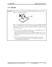
... from the usual polyimide cover), if any tape is peeled off . PORTÉGÉ R500 Maintenance Manual (960-634) [CONFIDENTIAL] 4-31 Pressure may cause data loss or damage to the device. 4.14 HDD/SSD 4 Replacement Procedures 4.14 HDD/SSD 4 Replacement Procedures CAUTION: Take care not to press on the surface. (2) Do not stick any tape...
... from the usual polyimide cover), if any tape is peeled off . PORTÉGÉ R500 Maintenance Manual (960-634) [CONFIDENTIAL] 4-31 Pressure may cause data loss or damage to the device. 4.14 HDD/SSD 4 Replacement Procedures 4.14 HDD/SSD 4 Replacement Procedures CAUTION: Take care not to press on the surface. (2) Do not stick any tape...
Maintenance Manual
Page 248
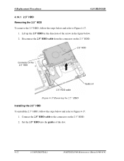
... the guides of the arrow in the figure below. 2. Lift up the 2.5" HDD in the direction of the slot. 4-32 [CONFIDENTIAL] PORTÉGÉ R500 Maintenance Manual (960-634) Disconnect the 2.5" HDD cable from the connector on the 2.5" HDD. 2. Connect the 2.5" HDD cable to the connector on the ... Figure 4-17 Removing the 2.5" HDD Installing the 2.5" HDD To install the 2.5" HDD, follow the steps below and refer to Figure 4-17. 1. 4 Replacement Procedures 4.14 HDD/SSD 4.14.1 2.5" HDD Removing the 2.5" HDD To remove the 2.5"HDD, follow the steps below and refer to Figure 4-17. 1.
... the guides of the arrow in the figure below. 2. Lift up the 2.5" HDD in the direction of the slot. 4-32 [CONFIDENTIAL] PORTÉGÉ R500 Maintenance Manual (960-634) Disconnect the 2.5" HDD cable from the connector on the 2.5" HDD. 2. Connect the 2.5" HDD cable to the connector on the ... Figure 4-17 Removing the 2.5" HDD Installing the 2.5" HDD To install the 2.5" HDD, follow the steps below and refer to Figure 4-17. 1. 4 Replacement Procedures 4.14 HDD/SSD 4.14.1 2.5" HDD Removing the 2.5" HDD To remove the 2.5"HDD, follow the steps below and refer to Figure 4-17. 1.

Maintenance Manual
Page 249
Disconnect the 1.8" HDD cable from the 1.8" HDD. 2. CAUTION: The 1.8-inch HDD cable and SSD cable are the same. 1.8" HDD Cushion x4 1.8" HDD cable Connector of the arrow in the direction of the 1.8" HDD Figure 4-18 Removing the 1.8" HDD Guide x4 PORTÉGÉ R500 Maintenance Manual (960-634) [CONFIDENTIAL] 4-33 Turn over the 1.8" HDD in the figure below and refer to Figure 4-18. 1. 4.14 HDD/SSD 4 Replacement Procedures 4.14.2 1.8" HDD Removing the 1.8" HDD To remove the 1.8" HDD, follow the steps below and remove four cushions from the connector on the 1.8" HDD.
Disconnect the 1.8" HDD cable from the 1.8" HDD. 2. CAUTION: The 1.8-inch HDD cable and SSD cable are the same. 1.8" HDD Cushion x4 1.8" HDD cable Connector of the arrow in the direction of the 1.8" HDD Figure 4-18 Removing the 1.8" HDD Guide x4 PORTÉGÉ R500 Maintenance Manual (960-634) [CONFIDENTIAL] 4-33 Turn over the 1.8" HDD in the figure below and refer to Figure 4-18. 1. 4.14 HDD/SSD 4 Replacement Procedures 4.14.2 1.8" HDD Removing the 1.8" HDD To remove the 1.8" HDD, follow the steps below and remove four cushions from the connector on the 1.8" HDD.
Maintenance Manual
Page 250
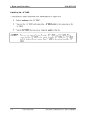
...HDD shall be broken. Turn the 1.8" HDD face up and set it into the guides of system board for 2.5" HDD. 4-34 [CONFIDENTIAL] PORTÉGÉ R500 Maintenance Manual (960-634) CAUTION: There are two types of the slot. When connecting the 1.8" HDD to the connector on the 1.8" HDD. 3. Do not ...connect the 1.8" HDD to the 1.8" HDD. 2. Set four cushions to the system board for 2.5" HDD and 1.8" HDD. 4 Replacement Procedures 4.14 HDD/SSD Installing the 1.8" HDD To install the 1.8" HDD, follow the steps below and refer to Figure 4-18. 1.
...HDD shall be broken. Turn the 1.8" HDD face up and set it into the guides of system board for 2.5" HDD. 4-34 [CONFIDENTIAL] PORTÉGÉ R500 Maintenance Manual (960-634) CAUTION: There are two types of the slot. When connecting the 1.8" HDD to the connector on the 1.8" HDD. 3. Do not ...connect the 1.8" HDD to the 1.8" HDD. 2. Set four cushions to the system board for 2.5" HDD and 1.8" HDD. 4 Replacement Procedures 4.14 HDD/SSD Installing the 1.8" HDD To install the 1.8" HDD, follow the steps below and refer to Figure 4-18. 1.
Maintenance Manual
Page 251
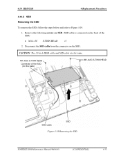
CAUTION: The 1.8-inch HDD cable and SSD cable are the same. 4.14 HDD/SSD 4 Replacement Procedures 4.14.3 SSD Removing the SSD To remove the SSD, follow the steps below and refer to Figure 4-19. 1. M1.4x3C S-THIN HEAD Connector of the SSD) • M1.4×3C S-THIN HEAD ×3 2. Disconnect the SSD cable from the connector on the back of the SSD (On the back) M1.4x3C S-THIN HEAD SSD cable SSD Figure 4-19 Removing the SSD PORTÉGÉ R500 Maintenance Manual (960-634) [CONFIDENTIAL] 4-35 Remove the following screws and SSD. (SSD cable is connected on the SSD.
CAUTION: The 1.8-inch HDD cable and SSD cable are the same. 4.14 HDD/SSD 4 Replacement Procedures 4.14.3 SSD Removing the SSD To remove the SSD, follow the steps below and refer to Figure 4-19. 1. M1.4x3C S-THIN HEAD Connector of the SSD) • M1.4×3C S-THIN HEAD ×3 2. Disconnect the SSD cable from the connector on the back of the SSD (On the back) M1.4x3C S-THIN HEAD SSD cable SSD Figure 4-19 Removing the SSD PORTÉGÉ R500 Maintenance Manual (960-634) [CONFIDENTIAL] 4-35 Remove the following screws and SSD. (SSD cable is connected on the SSD.
Maintenance Manual
Page 252
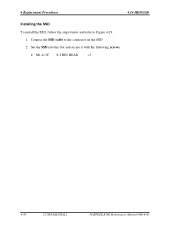
Set the SSD into the slot and secure it with the following screws. • M1.4×3C S-THIN HEAD ×3 4-36 [CONFIDENTIAL] PORTÉGÉ R500 Maintenance Manual (960-634) 4 Replacement Procedures 4.14 HDD/SSD Installing the SSD To install the SSD, follow the steps below and refer to the connector on the SSD. 2. Connect the SSD cable to Figure 4-19. 1.
Set the SSD into the slot and secure it with the following screws. • M1.4×3C S-THIN HEAD ×3 4-36 [CONFIDENTIAL] PORTÉGÉ R500 Maintenance Manual (960-634) 4 Replacement Procedures 4.14 HDD/SSD Installing the SSD To install the SSD, follow the steps below and refer to the connector on the SSD. 2. Connect the SSD cable to Figure 4-19. 1.
Maintenance Manual
Page 262
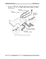
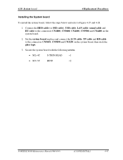
Disconnect the HDD cable (or SSD cable), USB cable, LAN cable, sound cable and BT cable from the connectors CN1800, CN9600, CN4100, CN9500 and CN4400 on the system board. USB cable (Connected to CN9600) BT cable (Connected to CN4400) LAN cable (Connected to CN4100) HDD cable or SSD cable (Connected to CN1800) Sound cable (Connected to CN9500) Figure 4-28 Removing the system board (2) 4-46 [CONFIDENTIAL] PORTÉGÉ R500 Maintenance Manual (960-634) 4 Replacement Procedures 4.18 System board 4.
Disconnect the HDD cable (or SSD cable), USB cable, LAN cable, sound cable and BT cable from the connectors CN1800, CN9600, CN4100, CN9500 and CN4400 on the system board. USB cable (Connected to CN9600) BT cable (Connected to CN4400) LAN cable (Connected to CN4100) HDD cable or SSD cable (Connected to CN1800) Sound cable (Connected to CN9500) Figure 4-28 Removing the system board (2) 4-46 [CONFIDENTIAL] PORTÉGÉ R500 Maintenance Manual (960-634) 4 Replacement Procedures 4.18 System board 4.
Maintenance Manual
Page 263
... ×1 • M3×5C BIND ×2 PORTÉGÉ R500 Maintenance Manual (960-634) [CONFIDENTIAL] 4-47 Connect the HDD cable (or SSD cable), USB cable, LAN cable, sound cable and BT cable to Figure 4-27 and 4-28. 1. 4.18 System board 4 Replacement Procedures Installing the System board To install the system board, follow...
... ×1 • M3×5C BIND ×2 PORTÉGÉ R500 Maintenance Manual (960-634) [CONFIDENTIAL] 4-47 Connect the HDD cable (or SSD cable), USB cable, LAN cable, sound cable and BT cable to Figure 4-27 and 4-28. 1. 4.18 System board 4 Replacement Procedures Installing the System board To install the system board, follow...


