Service Manual
Page 20
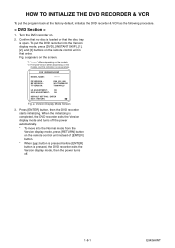
..., and this indication is open. a appears on the screen. *1: "*******" differs depending on the models. *2: Firmware Version differs depending on the remote control unit instead of [ENTER] button. * When [ ] button is pressed before [ENTER] button is pressed, the DVD recorder exits the ... recorder starts initializing. To put the program back at the factory-default, initialize the DVD recorder & VCR as the following procedure. < DVD Section > 1. Fig. a Version Display Mode Screen 3. Turn the DVD recorder on the remote control unit in that the disc tray is one example.
..., and this indication is open. a appears on the screen. *1: "*******" differs depending on the models. *2: Firmware Version differs depending on the remote control unit instead of [ENTER] button. * When [ ] button is pressed before [ENTER] button is pressed, the DVD recorder exits the ... recorder starts initializing. To put the program back at the factory-default, initialize the DVD recorder & VCR as the following procedure. < DVD Section > 1. Fig. a Version Display Mode Screen 3. Turn the DVD recorder on the remote control unit in that the disc tray is one example.
Service Manual
Page 21
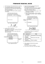
... this indication is one example. Select the firmware version pressing arrow buttons, then press [ENTER]. d appears on the tray. 2. e: 1) When Fig. The file on the remote control unit in Version Up Mode 3. Firm Update Mode VOL_200704130934 1 WL5T34280H1E 2 WL5T34281H1E 3 WL5T34282H1E 4 WL5T34283H1E ver. c Update Disc Screen Fig. d Programming Mode Screen Fig. b VFD in...
... this indication is one example. Select the firmware version pressing arrow buttons, then press [ENTER]. d appears on the tray. 2. e: 1) When Fig. The file on the remote control unit in Version Up Mode 3. Firm Update Mode VOL_200704130934 1 WL5T34280H1E 2 WL5T34281H1E 3 WL5T34282H1E 4 WL5T34283H1E ver. c Update Disc Screen Fig. d Programming Mode Screen Fig. b VFD in...
Service Manual
Page 25
...(DVD MECHANISM & DVD MAIN BOARD ASSEMBLY). Yes Is the control voltage normally inputted into No Pin(85) of the RS1501 (remote control receiver) when the remote control unit is not functioning. Check the key switches and their periphery, and replace P1 (BOARD MCV) if defective. Check...? Yes Check IC1501 and their periphery, and replace P1 (BOARD MCV) if defective. DVD PLAY ----- Terminal voltage of No the RS1501 (remote control receiver)? Re-install some key switches correctly or replace P1 (BOARD MCV) if defective. Check AL+5V line and replace P1 (BOARD...
...(DVD MECHANISM & DVD MAIN BOARD ASSEMBLY). Yes Is the control voltage normally inputted into No Pin(85) of the RS1501 (remote control receiver) when the remote control unit is not functioning. Check the key switches and their periphery, and replace P1 (BOARD MCV) if defective. Check...? Yes Check IC1501 and their periphery, and replace P1 (BOARD MCV) if defective. DVD PLAY ----- Terminal voltage of No the RS1501 (remote control receiver)? Re-install some key switches correctly or replace P1 (BOARD MCV) if defective. Check AL+5V line and replace P1 (BOARD...
Service Manual
Page 31
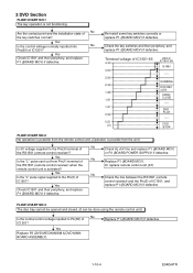
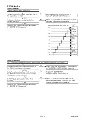
... of the RS1501 (remote control receiver) when the remote control unit is not functioning. Terminal voltage of IC1501-86 4.30 3.60 2.90 2.39 1.98 1.61 1.27 0.92 0.51 (V) KEY-1 IC1501-86 CH DOWN CH UP D/V OUTPUT REC /OTR FF REW PLAY STOP /EJECT POWER FLOW CHART NO.2 No VCR operation is possible from... the remote control unit. (Operation is possible from Pin(1) terminal of No the key switches normal? Replace P1 (BOARD MCV...
... of the RS1501 (remote control receiver) when the remote control unit is not functioning. Terminal voltage of IC1501-86 4.30 3.60 2.90 2.39 1.98 1.61 1.27 0.92 0.51 (V) KEY-1 IC1501-86 CH DOWN CH UP D/V OUTPUT REC /OTR FF REW PLAY STOP /EJECT POWER FLOW CHART NO.2 No VCR operation is possible from... the remote control unit. (Operation is possible from Pin(1) terminal of No the key switches normal? Replace P1 (BOARD MCV...
Service Manual
Page 41
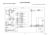
... 18 6G CLK 1 DIN 28 STB 2 8 DISPLAY-CLK 7 DISPLAY-DATA 6 DISPLAY-ENA 5 REMOTE 17 7G 7 P9 8 P8 9 P1 10 P2 11 P3 REMOTE SENSOR RS1501 IIC-BUS SCL 18 IIC-BUS SDA 17 Hi-Fi-H-SW 30 Hi-Fi/NOR-IN... 78 12 P4 13 P5 14 P6 16 P7 VCR-AUDIO-MUTE 31 D-REC 29 Q1501 TIMER+5V...YCA-CS 21 C-SYNC-IN 50 D-V SYNC 24 V-ENV 83 C-ROTA 98 RF-SW 23 H-A-SW 99 BOARD POWER SWITCH KEY SWITCH (VCR) H-A-COMP 100 VIDEO-SW1 59 VIDEO-SW2 58 SW1620 VIDEO-SW3 57 POWER CN2212 CN2211 D1569 POWER 4 POWER-SW 4 1 AL+5V...
... 18 6G CLK 1 DIN 28 STB 2 8 DISPLAY-CLK 7 DISPLAY-DATA 6 DISPLAY-ENA 5 REMOTE 17 7G 7 P9 8 P8 9 P1 10 P2 11 P3 REMOTE SENSOR RS1501 IIC-BUS SCL 18 IIC-BUS SDA 17 Hi-Fi-H-SW 30 Hi-Fi/NOR-IN... 78 12 P4 13 P5 14 P6 16 P7 VCR-AUDIO-MUTE 31 D-REC 29 Q1501 TIMER+5V...YCA-CS 21 C-SYNC-IN 50 D-V SYNC 24 V-ENV 83 C-ROTA 98 RF-SW 23 H-A-SW 99 BOARD POWER SWITCH KEY SWITCH (VCR) H-A-COMP 100 VIDEO-SW1 59 VIDEO-SW2 58 SW1620 VIDEO-SW3 57 POWER CN2212 CN2211 D1569 POWER 4 POWER-SW 4 1 AL+5V...
Service Manual
Page 77
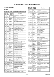
...NU Not Used 13 - NU Not Used 1-16-1 E9KGAPIN OUT Name Function 28 - NU Not Used 12 - NU Not Used 5 IN REMOTE Remote Control Sensor 6 OUT DISPLAYENA FL Display Driver IC Enable Control Output Signal 7 OUT DISPLAYDATA FL Display Driver IC Data Control Output Signal 8 OUT... DISPLAYCLK FL Display Driver IC Clock Control Output Signal 9 - IC PIN FUNCTION DESCRIPTIONS < VCR Section > IC1501 (SYSTEM CONTROL MICROPROCESSOR) Pin IN/ Signal No. GND Ground 49 IN VIDEO-IN Composite Video Signal Input 50 IN C-...
...NU Not Used 13 - NU Not Used 1-16-1 E9KGAPIN OUT Name Function 28 - NU Not Used 12 - NU Not Used 5 IN REMOTE Remote Control Sensor 6 OUT DISPLAYENA FL Display Driver IC Enable Control Output Signal 7 OUT DISPLAYDATA FL Display Driver IC Data Control Output Signal 8 OUT... DISPLAYCLK FL Display Driver IC Clock Control Output Signal 9 - IC PIN FUNCTION DESCRIPTIONS < VCR Section > IC1501 (SYSTEM CONTROL MICROPROCESSOR) Pin IN/ Signal No. GND Ground 49 IN VIDEO-IN Composite Video Signal Input 50 IN C-...

Service Manual
Page 85
... 1B1 P000501410 N2465FL DECK ASSEMBLY CZD014/ VM2465 FM1001 P000490010 MMEZR12XNR01 MOTOR DC FAN 2D65BK100100 W2 P000501450 WPZ0221WJ001 WIRE TIE 220MM BLACK ACCESSORIES X1 P000501430 NB340UD REMOTE CONTROL UNIT NB340UD X5 P000457360 WPZ0152TM014 AV CORD WPZ0152TM014 ! Loca!
... 1B1 P000501410 N2465FL DECK ASSEMBLY CZD014/ VM2465 FM1001 P000490010 MMEZR12XNR01 MOTOR DC FAN 2D65BK100100 W2 P000501450 WPZ0221WJ001 WIRE TIE 220MM BLACK ACCESSORIES X1 P000501430 NB340UD REMOTE CONTROL UNIT NB340UD X5 P000457360 WPZ0152TM014 AV CORD WPZ0152TM014 ! Loca!


