Service Manual
Page 3
... List TABLE OF CONTENTS Specifications 1-1-1 Laser Beam Safety Precautions 1-2-1 Important Safety Precautions 1-3-1 Standard Notes for Servicing 1-4-1 Preparation for Servicing 1-5-1 Cabinet Disassembly Instructions 1-6-1 Electrical Adjustment Instructions 1-7-1 How to Initialize the DVD Recorder & VCR 1-8-1 Firmware Renewal Mode 1-9-1 Troubleshooting 1-10-1 Function Indicator Symbols 1-11-1 Block Diagrams 1-12-1 Schematic Diagrams / BOARD's and Test Points 1-13-1 Waveforms 1-14...
... List TABLE OF CONTENTS Specifications 1-1-1 Laser Beam Safety Precautions 1-2-1 Important Safety Precautions 1-3-1 Standard Notes for Servicing 1-4-1 Preparation for Servicing 1-5-1 Cabinet Disassembly Instructions 1-6-1 Electrical Adjustment Instructions 1-7-1 How to Initialize the DVD Recorder & VCR 1-8-1 Firmware Renewal Mode 1-9-1 Troubleshooting 1-10-1 Function Indicator Symbols 1-11-1 Block Diagrams 1-12-1 Schematic Diagrams / BOARD's and Test Points 1-13-1 Waveforms 1-14...
Service Manual
Page 6
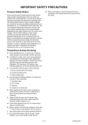
... specified insulating materials for safety. Parts that foreign objects (screws, solder droplets, etc.) do not remain inside the set is under review continuously and new instructions are to safety, other hazards. Prior to shipment from the factory, our products are carefully inspected to confirm with the recognized product safety and electrical...
... specified insulating materials for safety. Parts that foreign objects (screws, solder droplets, etc.) do not remain inside the set is under review continuously and new instructions are to safety, other hazards. Prior to shipment from the factory, our products are carefully inspected to confirm with the recognized product safety and electrical...
Service Manual
Page 8
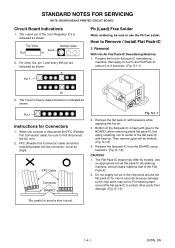
... the hot-air flat pack-IC desoldering machine, then apply hot air to the Flat Pack-IC (about 5 to Remove / Install Flat Pack-IC 1. Pin 1 Instructions for over 6 seconds because damage to the chip parts may differ by models. FFC (Flexible Foil Connector) cable should be sure to protect other ICs...
... the hot-air flat pack-IC desoldering machine, then apply hot air to the Flat Pack-IC (about 5 to Remove / Install Flat Pack-IC 1. Pin 1 Instructions for over 6 seconds because damage to the chip parts may differ by models. FFC (Flexible Foil Connector) cable should be sure to protect other ICs...

Service Manual
Page 11
... may occur due to avoid contacting semi-conductors with your clothing. BOARD Grounding Band 1MΩ BOARD 1MΩ Conductive Sheet or Copper Plate 1-4-4 DVDN_SN Instructions for Handling Semiconductors Electrostatic breakdown of the semi-conductors may be charged on clothing will not escape through the body grounding band, be placed. Because...
... may occur due to avoid contacting semi-conductors with your clothing. BOARD Grounding Band 1MΩ BOARD 1MΩ Conductive Sheet or Copper Plate 1-4-4 DVDN_SN Instructions for Handling Semiconductors Electrostatic breakdown of the semi-conductors may be charged on clothing will not escape through the body grounding band, be placed. Because...
Service Manual
Page 12
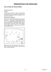
... FOR SERVICING How to Enter the Service Mode About Optical Sensors Caution: An optical sensor system is on this equipment. Carefully read and follow the instructions below. Otherwise the unit may operate erratically. This will stop the function of Tape Start Sensor, Tape End Sensor and Reel Sensors. (If these TPs..., the function of the tape to the start or the end of the sensors will be loaded into the Deck Mechanism Assembly and press the [ O ] (VCR) button.
... FOR SERVICING How to Enter the Service Mode About Optical Sensors Caution: An optical sensor system is on this equipment. Carefully read and follow the instructions below. Otherwise the unit may operate erratically. This will stop the function of Tape Start Sensor, Tape End Sensor and Reel Sensors. (If these TPs..., the function of the tape to the start or the end of the sensors will be loaded into the Deck Mechanism Assembly and press the [ O ] (VCR) button.
Service Manual
Page 13
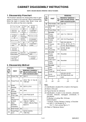
...Panel Rear Unit [13] BOARD Holder [15] Deck Assembly [16] BOARD Power Switch [17] BOARD DVD open / close Switch [14] VCR Chassis Unit [18] BOARD Main [19] Deck Pedestal 2. No. REMOVE/*UNHOOK/ UNLOCK/RELEASE/ UNPLUG/DESOLDER Note [1] Cover Top D1 7(S-1)...Locking Tabs (L-1) (5): Refer to be removed, unhooked, unlocked, released, unplugged, unclamped, or desoldered. ID/ LOC. CABINET DISASSEMBLY INSTRUCTIONS NOTE: BOARD MEANS PRINTED CIRCUIT BOARD. 1. VCR [14] Chassis Unit 5(S-13), 4(S-14), D8 (S-15), (S-16), (S-17), --- (S-18), Board Washer [15] Deck Assembly...
...Panel Rear Unit [13] BOARD Holder [15] Deck Assembly [16] BOARD Power Switch [17] BOARD DVD open / close Switch [14] VCR Chassis Unit [18] BOARD Main [19] Deck Pedestal 2. No. REMOVE/*UNHOOK/ UNLOCK/RELEASE/ UNPLUG/DESOLDER Note [1] Cover Top D1 7(S-1)...Locking Tabs (L-1) (5): Refer to be removed, unhooked, unlocked, released, unplugged, unclamped, or desoldered. ID/ LOC. CABINET DISASSEMBLY INSTRUCTIONS NOTE: BOARD MEANS PRINTED CIRCUIT BOARD. 1. VCR [14] Chassis Unit 5(S-13), 4(S-14), D8 (S-15), (S-16), (S-17), --- (S-18), Board Washer [15] Deck Assembly...
Service Manual
Page 19
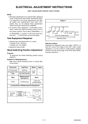
...: May cause Head Switching noise or vertical jitter in the center position: Press either [TRACKING ] or [TRACKING ] button on the front panel first, then the [ O ] (VCR) button on the front panel. NOTE: 1.Electrical adjustments are required after all repairs and replacements have been completed. ELECTRICAL ADJUSTMENT...
...: May cause Head Switching noise or vertical jitter in the center position: Press either [TRACKING ] or [TRACKING ] button on the front panel first, then the [ O ] (VCR) button on the front panel. NOTE: 1.Electrical adjustments are required after all repairs and replacements have been completed. ELECTRICAL ADJUSTMENT...


