
Operating Instructions
Page 1
Please check with your local Sony Authorized Dealer. © 2015 Sony Corporation VPL-FHZ65/FHZ60/FHZ57 VPL-FWZ65/FWZ60 Not all models are available in all countries and area. 4-573-698-17 (1) Data Projector Operating Instructions Before operating the unit, please read this manual and supplied Quick Reference Manual thoroughly and retain it for future reference.
Please check with your local Sony Authorized Dealer. © 2015 Sony Corporation VPL-FHZ65/FHZ60/FHZ57 VPL-FWZ65/FWZ60 Not all models are available in all countries and area. 4-573-698-17 (1) Data Projector Operating Instructions Before operating the unit, please read this manual and supplied Quick Reference Manual thoroughly and retain it for future reference.

Operating Instructions
Page 2
... Overview Location and Function of Controls .... 4 Main Unit 4 Terminals 5 Remote Commander and Control Panel 6 Preparation Connecting the Projector 9 Connecting a Computer 9 Connecting Video Equipment .... 10 Connecting an External Monitor and Audio Equipment 12 Connecting Network Equipment 13 ... for Trapezoidal Distortion of the Projected Image (Keystone Adjustment 19 Correcting Image Twist (Warp Correction Feature 20 Blending Projections from Multiple Projectors on a Screen 22 Turning Off the Power 23 Adjustments and Settings Using a Menu Using a Menu 24 The Picture Menu ...
... Overview Location and Function of Controls .... 4 Main Unit 4 Terminals 5 Remote Commander and Control Panel 6 Preparation Connecting the Projector 9 Connecting a Computer 9 Connecting Video Equipment .... 10 Connecting an External Monitor and Audio Equipment 12 Connecting Network Equipment 13 ... for Trapezoidal Distortion of the Projected Image (Keystone Adjustment 19 Correcting Image Twist (Warp Correction Feature 20 Blending Projections from Multiple Projectors on a Screen 22 Turning Off the Power 23 Adjustments and Settings Using a Menu Using a Menu 24 The Picture Menu ...

Operating Instructions
Page 4
B Overview Location and Function of the projector. http://www.kensington.com/ n Antitheft bar Connects to an optional antitheft cable manufactured by Kensington. f Terminals (page 5) g Front feet (adjustable) (page 19) h LENS RELEASE button (...
B Overview Location and Function of the projector. http://www.kensington.com/ n Antitheft bar Connects to an optional antitheft cable manufactured by Kensington. f Terminals (page 5) g Front feet (adjustable) (page 19) h LENS RELEASE button (...

Operating Instructions
Page 5
Connect external audio equipment to output audio (page 12). • The audio inputs of the projector are shared. As for images, the signal input from INPUT A is output from OUTPUT A, and the signal input from INPUT B is output from the audio ...
Connect external audio equipment to output audio (page 12). • The audio inputs of the projector are shared. As for images, the signal input from INPUT A is output from OUTPUT A, and the signal input from INPUT B is output from the audio ...

Operating Instructions
Page 6
... lens. c Operating a menu (page 24) ENTER /V/v/B/b (arrow) keys MENU key RETURN key RESET key Control Panel d Adjusting the image (page 18) FOCUS key Use this projector.
... lens. c Operating a menu (page 24) ENTER /V/v/B/b (arrow) keys MENU key RETURN key RESET key Control Panel d Adjusting the image (page 18) FOCUS key Use this projector.

Operating Instructions
Page 7
... zoom icon to the point on the image you wish to enlarge. 3 Press the D ZOOM + key or the D ZOOM - Energy-saving mode consists of the projector. ECO: Sets each mode to the optimum energy-saving value. • With No Input: Standby 7 MUTING key Mutes the audio output. depending on the resolution...
... zoom icon to the point on the image you wish to enlarge. 3 Press the D ZOOM + key or the D ZOOM - Energy-saving mode consists of the projector. ECO: Sets each mode to the optimum energy-saving value. • With No Input: Standby 7 MUTING key Mutes the audio output. depending on the resolution...

Operating Instructions
Page 8
... toward the remote control receiver. • The shorter the distance between the Remote Commander and the projector is, the wider the angle within which the Remote Commander can control only the projector with a connecting cable (stereo mini plug (not supplied)) when using the network or network control function...from the Remote Commander. 8 For details on ECO Mode settings, see "With No Input," "With Static Signal," and "Standby Mode" on the projector with the same ID mode as that of the Remote Commander. If you assign a different ID number to each item of the Remote Commander. ...
... toward the remote control receiver. • The shorter the distance between the Remote Commander and the projector is, the wider the angle within which the Remote Commander can control only the projector with a connecting cable (stereo mini plug (not supplied)) when using the network or network control function...from the Remote Commander. 8 For details on ECO Mode settings, see "With No Input," "With Static Signal," and "Standby Mode" on the projector with the same ID mode as that of the Remote Commander. If you assign a different ID number to each item of the Remote Commander. ...
Operating Instructions
Page 9
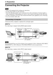
... the plug, not the cable itself. • For more information, refer also to 1920 × 1200 pixels (VPL-FHZ65/ FHZ60/FHZ57) or 1280 × 800 pixels (VPL-FWZ65/FWZ60) for the external monitor. B Preparation Connecting the Projector Notes • Turn off all equipment before making any connections. • Use the proper cables for each...
... the plug, not the cable itself. • For more information, refer also to 1920 × 1200 pixels (VPL-FHZ65/ FHZ60/FHZ57) or 1280 × 800 pixels (VPL-FWZ65/FWZ60) for the external monitor. B Preparation Connecting the Projector Notes • Turn off all equipment before making any connections. • Use the proper cables for each...

Operating Instructions
Page 10
...Video Equipment Connections with a VHS videocassette recorder, DVD player, or BD player are recommended.) • The HDMI terminal of this projector is not compatible with DSD (Direct Stream Digital) signal or CEC (Consumer Electronics Control) signal. VIDEO IN For connecting video equipment ... HDMI-compatible equipment which has the HDMI Logo. • Use a high speed HDMI cable(s) on which the cable type logo is specified. (Sony products are explained for each input signal. stereo mini plug) (not supplied) 10 BNC cable terminal (not supplied) Video equipment Audio output terminal ...
...Video Equipment Connections with a VHS videocassette recorder, DVD player, or BD player are recommended.) • The HDMI terminal of this projector is not compatible with DSD (Direct Stream Digital) signal or CEC (Consumer Electronics Control) signal. VIDEO IN For connecting video equipment ... HDMI-compatible equipment which has the HDMI Logo. • Use a high speed HDMI cable(s) on which the cable type logo is specified. (Sony products are explained for each input signal. stereo mini plug) (not supplied) 10 BNC cable terminal (not supplied) Video equipment Audio output terminal ...

Operating Instructions
Page 11
... equipment which has the HDMI Logo. • Use a high speed HDMI cable(s) on which the cable type logo is specified. (Sony products are recommended.) • The HDMI terminal of this projector is not compatible with an HDMI output terminal. INPUT A For connecting video equipment with a YPBPR output terminal. Video equipment YPBPR output...
... equipment which has the HDMI Logo. • Use a high speed HDMI cable(s) on which the cable type logo is specified. (Sony products are recommended.) • The HDMI terminal of this projector is not compatible with an HDMI output terminal. INPUT A For connecting video equipment with a YPBPR output terminal. Video equipment YPBPR output...

Operating Instructions
Page 15
...; Connect this unit and the HDBaseT transmitter directly without a hub or router. 15 • The transmittable distance of the cable is set to control the projector. If it exceeds 100 m (approx. 328 feet), it may cause the image or the sound to break up, or cause a multifunction in LAN communication...
...; Connect this unit and the HDBaseT transmitter directly without a hub or router. 15 • The transmittable distance of the cable is set to control the projector. If it exceeds 100 m (approx. 328 feet), it may cause the image or the sound to break up, or cause a multifunction in LAN communication...

Operating Instructions
Page 17
... unit or the ? You can select the input source using Direct input select keys on the distance between the projector and screen. How to switch the computer to output to the projector varies, depending on the type of computer. (Example) + 7 Adjust the focus, size, and position of ... the connected equipment. 5 Select the input source. Press the INPUT key on the projector. Press the INPUT key repeatedly or the V/v key to select an image to the projector (page 9). 3 Turn on the projector to external display by changing your computer's setting. The signal icon appears on projection ...
... unit or the ? You can select the input source using Direct input select keys on the distance between the projector and screen. How to switch the computer to output to the projector varies, depending on the type of computer. (Example) + 7 Adjust the focus, size, and position of ... the connected equipment. 5 Select the input source. Press the INPUT key on the projector. Press the INPUT key repeatedly or the V/v key to select an image to the projector (page 9). 3 Turn on the projector to external display by changing your computer's setting. The signal icon appears on projection ...

Operating Instructions
Page 18
... the Remote Commander then press the V/ v/B/b key to adjust the position. Press the LENS SHIFT/SHIFT key on the projector or the Remote Commander then press the V/v/B/b key to adjust the size. Focus lever Zoom lever Peripheral focus ring 18 You can adjust the focus ..., Size, and Position of the Projected Image Focus Size (Zoom) Position (Lens shift) When attaching the Electric focus lens Press the FOCUS key on the projector or the Remote Commander then press the V/ v/B/b key to the center position of the peripheral area by rotating the peripheral focus ring.
... the Remote Commander then press the V/ v/B/b key to adjust the position. Press the LENS SHIFT/SHIFT key on the projector or the Remote Commander then press the V/v/B/b key to adjust the size. Focus lever Zoom lever Peripheral focus ring 18 You can adjust the focus ..., Size, and Position of the Projected Image Focus Size (Zoom) Position (Lens shift) When attaching the Electric focus lens Press the FOCUS key on the projector or the Remote Commander then press the V/ v/B/b key to the center position of the peripheral area by rotating the peripheral focus ring.

Operating Instructions
Page 19
... on your fingers. • Do not push hard on the top of the projector with the front feet (adjustable) extended. Adjusting the tilt of the projector with the front feet (adjustable) When the projector is installed on an uneven surface, you can display a pattern for Trapezoidal Distortion of the Projected Image (Keystone Adjustment...
... on your fingers. • Do not push hard on the top of the projector with the front feet (adjustable) extended. Adjusting the tilt of the projector with the front feet (adjustable) When the projector is installed on an uneven surface, you can display a pattern for Trapezoidal Distortion of the Projected Image (Keystone Adjustment...

Operating Instructions
Page 22
...the ID mode. Then, set "Edge Blending" to adjust the projected positions from Multiple Projectors on the blending start position or the blending width, the menu may overlap with qualified Sony personnel. 22 Finely adjust each tone as necessary. 5 Adjust the color matching setting.... Your own installation may vary according to the situation. • When multiple projectors are set "Edge Blending" to 3) (page 36). ...
...the ID mode. Then, set "Edge Blending" to adjust the projected positions from Multiple Projectors on the blending start position or the blending width, the menu may overlap with qualified Sony personnel. 22 Finely adjust each tone as necessary. 5 Adjust the color matching setting.... Your own installation may vary according to the situation. • When multiple projectors are set "Edge Blending" to 3) (page 36). ...

Operating Instructions
Page 23
Turning Off the Power 1 Press the ?/1 key on the main unit or the 1 key on the Remote Commander. The projector starts shutdown and turns off. 2 Unplug the AC power cord from the wall outlet. 23
Turning Off the Power 1 Press the ?/1 key on the main unit or the 1 key on the Remote Commander. The projector starts shutdown and turns off. 2 Unplug the AC power cord from the wall outlet. 23

Operating Instructions
Page 25
...% of light output of each mode. 25 The higher the setting, the sharper the picture. On/Off: Brightness is set to suit projecting using multiple projectors. Standard: The image becomes brighter, and power consumption becomes higher. Dark images are initialized to produce a "dynamic" picture. Adjusts brightness of "Color Temp." however, the...
...% of light output of each mode. 25 The higher the setting, the sharper the picture. On/Off: Brightness is set to suit projecting using multiple projectors. Standard: The image becomes brighter, and power consumption becomes higher. Dark images are initialized to produce a "dynamic" picture. Adjusts brightness of "Color Temp." however, the...

Operating Instructions
Page 26
... the contrast enhancer. Green (y): Adjusts the chromaticity point of dust and dirt. 26 High/Middle/Low: You can select R/G/B for the selected color. Notes *1: The projector may not be able to a 2.4 gamma curve. Off: Select this option. Auto: Precisely reproduces the image from "Red," "Green," and "Blue." Setting items Expert Setting...
... the contrast enhancer. Green (y): Adjusts the chromaticity point of dust and dirt. 26 High/Middle/Low: You can select R/G/B for the selected color. Notes *1: The projector may not be able to a 2.4 gamma curve. Off: Select this option. Auto: Precisely reproduces the image from "Red," "Green," and "Blue." Setting items Expert Setting...

Operating Instructions
Page 27
This projector is not to be used as a device for medical diagnosis. *4: When a video signal is input, this option is available. *5: When a progressive signal is input, this option is input from the DVI-D input terminal (INPUT B), HDMI input terminal (INPUT C), or HDBaseT input terminal (INPUT D). *2: The display position of the status during the test works together with the "Menu Position" setting (page 32). *3: Available when a computer signal is not available. 27
This projector is not to be used as a device for medical diagnosis. *4: When a video signal is input, this option is available. *5: When a progressive signal is input, this option is input from the DVI-D input terminal (INPUT B), HDMI input terminal (INPUT C), or HDBaseT input terminal (INPUT D). *2: The display position of the status during the test works together with the "Menu Position" setting (page 32). *3: Available when a computer signal is not available. 27

Operating Instructions
Page 28
... the setting, the image farther left. APA*4 *5 Automatically adjusts the projected image to fit the maximum projected image size. Notes *1: • Note that if the projector is used for profit or for public viewing, modifying the original picture by moving up , and as the setting decreases. Setting items Description Aspect*1 Changes...
... the setting, the image farther left. APA*4 *5 Automatically adjusts the projected image to fit the maximum projected image size. Notes *1: • Note that if the projector is used for profit or for public viewing, modifying the original picture by moving up , and as the setting decreases. Setting items Description Aspect*1 Changes...


