Operating Instructions
Page 5
...Rear/Right Side/Bottom 10 Control Panel 12 Connector Panel 12 Remote Commander 13 Setting Up and Projecting Installing the Projector 16 Connecting the Projector 17 Connecting with a Computer ......17 Connecting with a VCR or 15k RGB/Component Equipment 19 Selecting the Menu ...Language ..........21 Projecting 23 Effective Tools for Your Presentation 27 The INSTALL SETTING Menu ..... 34 The INFORMATION Menu 35 Maintenance Maintenance 36 Replacing the Lamp...
...Rear/Right Side/Bottom 10 Control Panel 12 Connector Panel 12 Remote Commander 13 Setting Up and Projecting Installing the Projector 16 Connecting the Projector 17 Connecting with a Computer ......17 Connecting with a VCR or 15k RGB/Component Equipment 19 Selecting the Menu ...Language ..........21 Projecting 23 Effective Tools for Your Presentation 27 The INSTALL SETTING Menu ..... 34 The INFORMATION Menu 35 Maintenance Maintenance 36 Replacing the Lamp...
Operating Instructions
Page 36
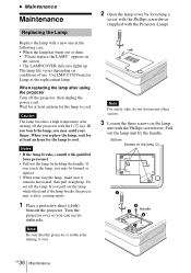
... hour for the lamp to cool. Pull out the lamp unit by holding the handle. Do not tilt the lamp. Use LMP-C150 Projector Lamp as the replacement lamp. appears on the lamp (3) Handle GB 36 Maintenance Caution The lamp becomes a high temperature after using the projector Turn off the projector with qualified Sony personnel. • Pull out the lamp by the handle...
... hour for the lamp to cool. Pull out the lamp unit by holding the handle. Do not tilt the lamp. Use LMP-C150 Projector Lamp as the replacement lamp. appears on the lamp (3) Handle GB 36 Maintenance Caution The lamp becomes a high temperature after using the projector Turn off the projector with qualified Sony personnel. • Pull out the lamp by the handle...
Operating Instructions
Page 37
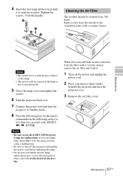
... Remove dust from the outside of the lamp. • The power will not turn on the remote commander in the following keys on if the lamp is securely in until it is not secured properly. 5 Close the lamp cover and tighten the screws. 6 Turn the projector back over. 7 Connect the power cord... and turn the projector to touch the glass surface of the ventilation holes with a...
... Remove dust from the outside of the lamp. • The power will not turn on the remote commander in the following keys on if the lamp is securely in until it is not secured properly. 5 Close the lamp cover and tighten the screws. 6 Turn the projector back over. 7 Connect the power cord... and turn the projector to touch the glass surface of the ventilation holes with a...
Operating Instructions
Page 40
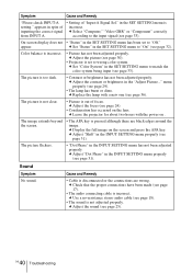
...8226; Contrast or brightness has not been adjusted properly. GB 40 Troubleshooting c Use a no-resistance stereo audio cable (see page 30). • Projector is disconnected or the connections are black edges around the image. c Set "Color System" in the INPUT SETTING menu properly (see page 36).... The picture is not adjusted properly. menu properly (see page 29). • The lamp has burnt or dims. c Replace the lamp with the power on . c Adjust "Dot Phase" in the SET SETTING menu to "Off." Sound Symptom No sound. Symptom ...
...8226; Contrast or brightness has not been adjusted properly. GB 40 Troubleshooting c Use a no-resistance stereo audio cable (see page 30). • Projector is disconnected or the connections are black edges around the image. c Set "Color System" in the INPUT SETTING menu properly (see page 36).... The picture is not adjusted properly. menu properly (see page 29). • The lamp has burnt or dims. c Replace the lamp with the power on . c Adjust "Dot Phase" in the SET SETTING menu to "Off." Sound Symptom No sound. Symptom ...
Operating Instructions
Page 41
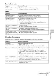
... (VPL-CX5) or SVGA (VPLCS5) (see page 26). c Set "Input-A Signal Sel." c Set the setting of the messages displayed on the power again (see page 17). c Replace the lamp. Please replace the LAMP. • It is blocking the ventilation holes. Frequency is out of the projector. ...The Remote Commander batteries are dead. The LAMP/COVER indicator lights up. • The lamp has reached the end of a computer is blocking the ventilation holes. c Consult with qualified Sony personnel. c Check to see page 36). • The lamp becomes a high temperature. c Input ...
... (VPL-CX5) or SVGA (VPLCS5) (see page 26). c Set "Input-A Signal Sel." c Set the setting of the messages displayed on the power again (see page 17). c Replace the lamp. Please replace the LAMP. • It is blocking the ventilation holes. Frequency is out of the projector. ...The Remote Commander batteries are dead. The LAMP/COVER indicator lights up. • The lamp has reached the end of a computer is blocking the ventilation holes. c Consult with qualified Sony personnel. c Check to see page 36). • The lamp becomes a high temperature. c Input ...
Operating Instructions
Page 44
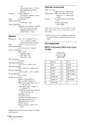
...kg (5 lb 15 oz) Power requirements AC 100 to 240 V, 50/60 Hz Power consumption Max. 240 W (Standby mode: VPL-CS5: 5 W VPL-CX5: 7 W) Heat dissipation 819 BTU Operating temperature 0°C to 35°C (32°F to 95°F) Operating humidity 35...DDC/SCL 8 GND (B) For details, please consult your nearest Sony office. GB 44 Specifications Optional accessories Projector Lamp LMP-C150 (for replacement) (1) Operating Instructions (1) Quick Reference Card (1) Ferrite core (1) Memory Stick (1) (VPL-CX5 only) Design and specifications are subject to 90% Supplied ...
...kg (5 lb 15 oz) Power requirements AC 100 to 240 V, 50/60 Hz Power consumption Max. 240 W (Standby mode: VPL-CS5: 5 W VPL-CX5: 7 W) Heat dissipation 819 BTU Operating temperature 0°C to 35°C (32°F to 95°F) Operating humidity 35...DDC/SCL 8 GND (B) For details, please consult your nearest Sony office. GB 44 Specifications Optional accessories Projector Lamp LMP-C150 (for replacement) (1) Operating Instructions (1) Quick Reference Card (1) Ferrite core (1) Memory Stick (1) (VPL-CX5 only) Design and specifications are subject to 90% Supplied ...
Operating Instructions
Page 48
... Hue 30 I Image Flip 34 INPUT A connector .......12 pin assignment 44 Input-A Signal Sel. .........33 Installation examples .....16 notes 7 unsuitable conditions .... 7 unsuitable installation .. 7 L Lamp Mode 34 Lamp replacement .......... 36 Lamp Timer 35 Language 33 selecting the menu language 21 Location and function of controls connector panel .......... 12 control panel 12 rear/right side/bottom...
... Hue 30 I Image Flip 34 INPUT A connector .......12 pin assignment 44 Input-A Signal Sel. .........33 Installation examples .....16 notes 7 unsuitable conditions .... 7 unsuitable installation .. 7 L Lamp Mode 34 Lamp replacement .......... 36 Lamp Timer 35 Language 33 selecting the menu language 21 Location and function of controls connector panel .......... 12 control panel 12 rear/right side/bottom...


