Operating Instructions
Page 1
Model No. STR-DG500 ©2006 Sony Corporation Serial No. Refer to them whenever you call upon your Sony dealer regarding this product. 2-662-258-12 (2) Multi Channel AV Receiver Operating Instructions Owner's Record The model and serial numbers are located on the rear of the unit. Record the serial number in the space provided below.
Model No. STR-DG500 ©2006 Sony Corporation Serial No. Refer to them whenever you call upon your Sony dealer regarding this product. 2-662-258-12 (2) Multi Channel AV Receiver Operating Instructions Owner's Record The model and serial numbers are located on the rear of the unit. Record the serial number in the space provided below.
Operating Instructions
Page 3
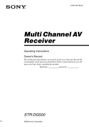
... and "DTS 96/24" are for example, "Models of area code AA only". About This Manual • The instructions in the text, for model STR-DG500. SURROUND BACK L L + - + - The recycling of materials will help to the area code, are clearly indicated in this manual are trademarks of ...Digital Theater Systems, Inc. 3GB Any difference in operation is shown on the remote. About area codes The area code of the receiver you purchased the product. For customers in Europe Disposal of Old Electrical & Electronic Equipment (Applicable in this manual describe the controls ...
... and "DTS 96/24" are for example, "Models of area code AA only". About This Manual • The instructions in the text, for model STR-DG500. SURROUND BACK L L + - + - The recycling of materials will help to the area code, are clearly indicated in this manual are trademarks of ...Digital Theater Systems, Inc. 3GB Any difference in operation is shown on the remote. About area codes The area code of the receiver you purchased the product. For customers in Europe Disposal of Old Electrical & Electronic Equipment (Applicable in this manual describe the controls ...
Marketing Specifications
Page 1
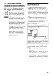
STR-DG500 Key Features 660W-110 Watts X 6 (8ohms 1kHz, THD 0.7%) Digital Cinema Auto Calibration w/ Mic (Auto Speaker Setup) HD Component Video Switching (2 Inputs/1 Output) 2 Optical Inputs /1 Coaxial Input A/V Sync Audio Video Receiver
STR-DG500 Key Features 660W-110 Watts X 6 (8ohms 1kHz, THD 0.7%) Digital Cinema Auto Calibration w/ Mic (Auto Speaker Setup) HD Component Video Switching (2 Inputs/1 Output) 2 Optical Inputs /1 Coaxial Input A/V Sync Audio Video Receiver
Marketing Specifications
Page 2
...Remote Control Color: Black UPC Code: 027242683129 Sony, Remote Commander, and Digital Cinema Sound are approximate. ©2006 Sony Electronics Inc. All Weights and measures are trademarks of Dolby Laboratories. STR-DG500 Features Audio Dolby® Digital Decoding: Yes ...Multi-Channel Input(s): 1 (Rear, 5.1 Channel) Subwoofer Output(s): 1 (Rear) Antenna Terminal (AM Loop): 1 (Rear) Antenna Terminal (FM 75 Ohm): 1 (Rear) Headphone Output(s): 1 (Front- Sony Electronics Inc. •16530 Via Esprillo •San Diego, CA 92127 •1-800-222-7669 •www.sony.com Audio Video Receiver...
...Remote Control Color: Black UPC Code: 027242683129 Sony, Remote Commander, and Digital Cinema Sound are approximate. ©2006 Sony Electronics Inc. All Weights and measures are trademarks of Dolby Laboratories. STR-DG500 Features Audio Dolby® Digital Decoding: Yes ...Multi-Channel Input(s): 1 (Rear, 5.1 Channel) Subwoofer Output(s): 1 (Rear) Antenna Terminal (AM Loop): 1 (Rear) Antenna Terminal (FM 75 Ohm): 1 (Rear) Headphone Output(s): 1 (Front- Sony Electronics Inc. •16530 Via Esprillo •San Diego, CA 92127 •1-800-222-7669 •www.sony.com Audio Video Receiver...
Service Manual
Page 1
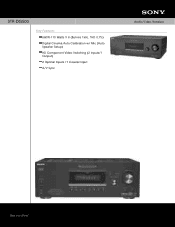
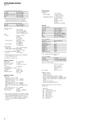
...channel minimum RMS power, with no more than 0.09 % total harmonic distortion from Dolby Laboratories. Continued on next page - STR-DG500/DG600 SERVICE MANUAL Ver. 1.1 2006. 04 Photo: STR-DG600: Silver type US Model Canadian Model STR-DG500/DG600 AEP Model UK Model STR-DG500 E Model STR-DG500/DG600 Australian Model STR-DG500..., THD 10 % 125 W + 125 W 1), 110 W + 110 W 3), 150 W/ch Models of area code US only) With 8 ohm loads, both channels driven, from 20 - 20,000 Hz; MULTI CHANNEL AV RECEIVER 9-887-127-02 2006D04-1 © 2006. 04 Sony Corporation Home Audio Division Published by...
...channel minimum RMS power, with no more than 0.09 % total harmonic distortion from Dolby Laboratories. Continued on next page - STR-DG500/DG600 SERVICE MANUAL Ver. 1.1 2006. 04 Photo: STR-DG600: Silver type US Model Canadian Model STR-DG500/DG600 AEP Model UK Model STR-DG500 E Model STR-DG500/DG600 Australian Model STR-DG500..., THD 10 % 125 W + 125 W 1), 110 W + 110 W 3), 150 W/ch Models of area code US only) With 8 ohm loads, both channels driven, from 20 - 20,000 Hz; MULTI CHANNEL AV RECEIVER 9-887-127-02 2006D04-1 © 2006. 04 Sony Corporation Home Audio Division Published by...
Service Manual
Page 2
...999 kHz) 6) You can change without notice. • Abbreviation CND : Canadian model E2 : 120 V AC area in any AM station, turn off the receiver. After tuning in E model TW : Taiwan model AUS : Australian model KR : Korea model MY : Malaysia model SP : Singapore model TH : Thai model... batteries (2) Optimizer microphone ECM-AC2 (1) Design and specifications are subject to change the AM tuning scale to 10 kHz (or 9 kHz), repeat the procedure. STR-DG500/DG600 Ver. 1.1 1) Measured under the following conditions: Area code US, CND AEP, UK, KR, MY, SP, TH E2, AUS TW Power requirements...
...999 kHz) 6) You can change without notice. • Abbreviation CND : Canadian model E2 : 120 V AC area in any AM station, turn off the receiver. After tuning in E model TW : Taiwan model AUS : Australian model KR : Korea model MY : Malaysia model SP : Singapore model TH : Thai model... batteries (2) Optimizer microphone ECM-AC2 (1) Design and specifications are subject to change the AM tuning scale to 10 kHz (or 9 kHz), repeat the procedure. STR-DG500/DG600 Ver. 1.1 1) Measured under the following conditions: Area code US, CND AEP, UK, KR, MY, SP, TH E2, AUS TW Power requirements...
Service Manual
Page 3
... in E model MY : Malaysia model SP : Singapore model TH : Thai model SAFETY-RELATED COMPONENT WARNING!! NE REMPLACER CES COMPOSANTS QUE PAR DES PIÈCES SONY DONT LES NUMÉROS SONT DONNÉS DANS CE MANUEL OU DANS LES SUPPLÉMENTS PUBLIÉS PAR... and Sanwa SH-63Trd are examples of a passive VOM that have an accurate lowvoltage scale. Leakage current can be measured by means of three methods. 1. STR-DG500/DG600 Ver. 1.1 SAFETY CHECK-OUT (US MODEL) After correcting the original service problem, perform the following safety check before releasing the set to use these...
... in E model MY : Malaysia model SP : Singapore model TH : Thai model SAFETY-RELATED COMPONENT WARNING!! NE REMPLACER CES COMPOSANTS QUE PAR DES PIÈCES SONY DONT LES NUMÉROS SONT DONNÉS DANS CE MANUEL OU DANS LES SUPPLÉMENTS PUBLIÉS PAR... and Sanwa SH-63Trd are examples of a passive VOM that have an accurate lowvoltage scale. Leakage current can be measured by means of three methods. 1. STR-DG500/DG600 Ver. 1.1 SAFETY CHECK-OUT (US MODEL) After correcting the original service problem, perform the following safety check before releasing the set to use these...

Service Manual
Page 4
... Section (DG600 39 4-28. Schematic Diagram - Schematic Diagram - ADCC Section 42 4-33. Power Section 46 5. Front Panel Section 59 5-3. STR-DG500/DG600 Ver. 1.1 TABLE OF CONTENTS 1. DISASSEMBLY 2-1. SB AMP Board (DG600 13 3. Block Diagram - Printed Wiring Boards - Printed Wiring Board...Video Section 36 4-24. XM Section (DG600: US, CND model 40 4-30. GENERAL Description and location of parts (STR-DG500 5 Description and location of parts (STR-DG600: US, CND model 7 2. Back Panel Section 11 2-4. Block Diagram - Printed Wiring Board - S-video Section 38...
... Section (DG600 39 4-28. Schematic Diagram - Schematic Diagram - ADCC Section 42 4-33. Power Section 46 5. Front Panel Section 59 5-3. STR-DG500/DG600 Ver. 1.1 TABLE OF CONTENTS 1. DISASSEMBLY 2-1. SB AMP Board (DG600 13 3. Block Diagram - Printed Wiring Boards - Printed Wiring Board...Video Section 36 4-24. XM Section (DG600: US, CND model 40 4-30. GENERAL Description and location of parts (STR-DG500 5 Description and location of parts (STR-DG600: US, CND model 7 2. Back Panel Section 11 2-4. Block Diagram - Printed Wiring Board - S-video Section 38...
Service Manual
Page 5
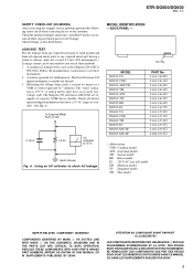
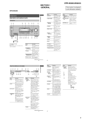
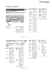
... (page 27). Lights up when multi DECODING lamp channel audio is actually being reproduced. AUTO SW LCR SL SR 8GB 5 STR-DG500: SECTION 1 GENERAL STR-DG500/DG600 This section is not set to "ANALOG" (page 60). E Remote sensor Receives signals from children. H MASTER VOLUME...8 ?/1 SPEAKERS (OFF/A/B /A+B) AUTO CAL MIC PHONES VIDEO 3 IN/PORTABLE AV IN VIDEO L AUDIO R MULTI CHANNEL DECODING DISPLAY INPUT MODE INPUT SELECTOR MASTER VOLUME MEMORY/ TUNING ENTER MODE TUNING 2CH A.F.D. D MULTI CHANNEL Lights up when the sleep timer is selected (page 52). G INPUT MODE...
... (page 27). Lights up when multi DECODING lamp channel audio is actually being reproduced. AUTO SW LCR SL SR 8GB 5 STR-DG500: SECTION 1 GENERAL STR-DG500/DG600 This section is not set to "ANALOG" (page 60). E Remote sensor Receives signals from children. H MASTER VOLUME...8 ?/1 SPEAKERS (OFF/A/B /A+B) AUTO CAL MIC PHONES VIDEO 3 IN/PORTABLE AV IN VIDEO L AUDIO R MULTI CHANNEL DECODING DISPLAY INPUT MODE INPUT SELECTOR MASTER VOLUME MEMORY/ TUNING ENTER MODE TUNING 2CH A.F.D. D MULTI CHANNEL Lights up when the sleep timer is selected (page 52). G INPUT MODE...
Service Manual
Page 6
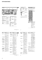
...tactile dots as an example only. Therefore, depending on the TV screen. White (L) Red (R) MULTI CHANNEL INPUT jack Black Connects to perform menu operations. D VIDEO/AUDIO INPUT/OUTPUT section AUDIO IN/ ... turn off the Sony audio/video components that the remote is displayed on the TV screen. Y AUTO CAL Press to select sound fields (MOVIE, MUSIC). STR-DG500/DG600 Rear panel...A AV ?/1 Function Press to use the control buttons to enter the value after selecting a channel, disc or track using the numeric buttons. preset/tune to the AM loop antenna supplied with this receiver (...
...tactile dots as an example only. Therefore, depending on the TV screen. White (L) Red (R) MULTI CHANNEL INPUT jack Black Connects to perform menu operations. D VIDEO/AUDIO INPUT/OUTPUT section AUDIO IN/ ... turn off the Sony audio/video components that the remote is displayed on the TV screen. Y AUTO CAL Press to select sound fields (MOVIE, MUSIC). STR-DG500/DG600 Rear panel...A AV ?/1 Function Press to use the control buttons to enter the value after selecting a channel, disc or track using the numeric buttons. preset/tune to the AM loop antenna supplied with this receiver (...
Service Manual
Page 7
... activated (page 55). TUNING + VIDEO 3 IN/PORTABLE AV IN VIDEO L AUDIO R DIGITAL(OPT) MULTI CHANNEL DECODING DISPLAY INPUT MODE INPUT SELECTOR MASTER VOLUME MEMORY/ CATEGORY ENTER MODE CATEGORY 2CH A.F.D. When you select a sound field using the receiver to "AUTO" and the source signal is a digital ...EX" lights up if the speaker output is turned off (page 30, 38, 39, 60, 85). button. continued 7US Getting Started Getting Started STR-DG500/DG600 Ver. 1.1 Name Function E Display The current status of the selected component or a list of parts Front panel 12 3 4 5 67 89...
... activated (page 55). TUNING + VIDEO 3 IN/PORTABLE AV IN VIDEO L AUDIO R DIGITAL(OPT) MULTI CHANNEL DECODING DISPLAY INPUT MODE INPUT SELECTOR MASTER VOLUME MEMORY/ CATEGORY ENTER MODE CATEGORY 2CH A.F.D. When you select a sound field using the receiver to "AUTO" and the source signal is a digital ...EX" lights up if the speaker output is turned off (page 30, 38, 39, 60, 85). button. continued 7US Getting Started Getting Started STR-DG500/DG600 Ver. 1.1 Name Function E Display The current status of the selected component or a list of parts Front panel 12 3 4 5 67 89...
Service Manual
Page 8
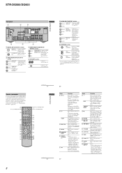
... supplied remote RM-AAP012 to operate the receiver and to control the Sony audio/video components that the remote is assigned to select the searching mode or unit for 5.1 channel sound (page 20). SPEAKERS L R ... Red (R) MULTI CHANNEL INPUT jack Black PRE OUT White (L) jack Red (R) Connects to a TV monitor (page 24). qa qs qd qf qg continued 11US 8 Getting Started 10US Name A AV ?/1 B ?/1 SLEEP C MULTI CH D ...or video input). You can also program the remote to select the wide picture mode. STR-DG500/DG600 Rear panel 1 2 3 DIGITAL OPTICAL VIDEO 1 IN VIDEO 2 IN MD/ ...
... supplied remote RM-AAP012 to operate the receiver and to control the Sony audio/video components that the remote is assigned to select the searching mode or unit for 5.1 channel sound (page 20). SPEAKERS L R ... Red (R) MULTI CHANNEL INPUT jack Black PRE OUT White (L) jack Red (R) Connects to a TV monitor (page 24). qa qs qd qf qg continued 11US 8 Getting Started 10US Name A AV ?/1 B ?/1 SLEEP C MULTI CH D ...or video input). You can also program the remote to select the wide picture mode. STR-DG500/DG600 Rear panel 1 2 3 DIGITAL OPTICAL VIDEO 1 IN VIDEO 2 IN MD/ ...
Service Manual
Page 9
...the sound to Multiplex, Bilingual or Multi channel TV sound of the VCR, DAT deck, or tape deck. Press ALT (G) and then press the numeric buttons to set up the remote. The buttons are factory assigned to control Sony components as references when operating the receiver. wl RM SET UP Press to... you press TOP MENU/ GUIDE or AV MENU, press the control button to display the - STR-DG500/DG600 Name S DISPLAY T Control buttons U TOP MENU/ GUIDE V AV MENU W Ha) XX Function Press to select information displayed on the TV screen of the input buttons, the receiver turns on. menu or on-screen ...
...the sound to Multiplex, Bilingual or Multi channel TV sound of the VCR, DAT deck, or tape deck. Press ALT (G) and then press the numeric buttons to set up the remote. The buttons are factory assigned to control Sony components as references when operating the receiver. wl RM SET UP Press to... you press TOP MENU/ GUIDE or AV MENU, press the control button to display the - STR-DG500/DG600 Name S DISPLAY T Control buttons U TOP MENU/ GUIDE V AV MENU W Ha) XX Function Press to select information displayed on the TV screen of the input buttons, the receiver turns on. menu or on-screen ...

Service Manual
Page 10
FRONT PANEL SECTION 2-3. STANDBY BOARD (Page 13) 2-4. SB AMP BOARD (DG600) (Page 13) 2-5. BACK PANEL SECTION (Page 11) (Page 11) 2-6. SET 2-1. CASE (Page 10) 2-2. DIGITAL BOARD (Page 12) 2-7. MAIN BOARD SECTION (Page 12) Note : Follow the disassembly procedure in the numerical order given. 2-1. CASE 2 two screws (case 3 TP2) 3 two screws (+BVTP 3 × 8) 4 case 1 two screws (case 3 TP2) 10 STR-DG500/DG600 SECTION 2 DISASSEMBLY Note : This set can be disassemble according to the following sequence.
FRONT PANEL SECTION 2-3. STANDBY BOARD (Page 13) 2-4. SB AMP BOARD (DG600) (Page 13) 2-5. BACK PANEL SECTION (Page 11) (Page 11) 2-6. SET 2-1. CASE (Page 10) 2-2. DIGITAL BOARD (Page 12) 2-7. MAIN BOARD SECTION (Page 12) Note : Follow the disassembly procedure in the numerical order given. 2-1. CASE 2 two screws (case 3 TP2) 3 two screws (+BVTP 3 × 8) 4 case 1 two screws (case 3 TP2) 10 STR-DG500/DG600 SECTION 2 DISASSEMBLY Note : This set can be disassemble according to the following sequence.

Service Manual
Page 11
FRONT PANEL SECTION 6 two screws (+BVTP 3 × 8) 2 CNP791 (4P) 1 CNP2000 (4P) STR-DG500/DG600 4 CNP202 (3P) 5 CNP503 (3P) 8 front panel section 2-3. BACK PANEL SECTION 1 CNP901 (2P) 2 CNP806 (3P) 3 CNS505 (23 core) 7 five screws (+BVTP 3 × 8) 0 screw (+BVTP 3 × 8) 7 ...
FRONT PANEL SECTION 6 two screws (+BVTP 3 × 8) 2 CNP791 (4P) 1 CNP2000 (4P) STR-DG500/DG600 4 CNP202 (3P) 5 CNP503 (3P) 8 front panel section 2-3. BACK PANEL SECTION 1 CNP901 (2P) 2 CNP806 (3P) 3 CNS505 (23 core) 7 five screws (+BVTP 3 × 8) 0 screw (+BVTP 3 × 8) 7 ...

Service Manual
Page 12
MAIN BOARD SECTION 7 screw 4 CNP802 (5P) (+BV3 (3-CR)) 6 two screws 3 CNP801 (3P) (+BV3 (3-CR)) 1 CNP600 (5P) 5 two screws (+BV3 (3-CR)) 2 CNP601 (4P) 8 MAIN board section 12 STR-DG500/DG600 2-4. DIGITAL BOARD 3 CNP504 (7P) 2 CNP503 (5P) 1 CNP505 (10P) 5 DIGITAL board 4 screw (+BVTP 3 × 8) 2-5.
MAIN BOARD SECTION 7 screw 4 CNP802 (5P) (+BV3 (3-CR)) 6 two screws 3 CNP801 (3P) (+BV3 (3-CR)) 1 CNP600 (5P) 5 two screws (+BV3 (3-CR)) 2 CNP601 (4P) 8 MAIN board section 12 STR-DG500/DG600 2-4. DIGITAL BOARD 3 CNP504 (7P) 2 CNP503 (5P) 1 CNP505 (10P) 5 DIGITAL board 4 screw (+BVTP 3 × 8) 2-5.

Service Manual
Page 14
...ES D D SP B OPT HDMI C SL SR SBL SBR AAC RDS EQ MONO A.DIRECT k m MHz [MULTI CHANNEL DECODING] LED light on the main power. 1. The message "S.F. CLR." The message "AUTO-BETICAL SELECT" appears...main power. When this mode is connected. STR-DG500/DG600 SECTION 3 TEST MODE FACTORY PRESET MODE * All preset contents are displayed for a moment. AM CHANNEL STEP 9 kHz/10 kHz SELECTION MODE (...used, the receiver scans the broadcasts that the antenna is activated. appears for a moment and select the desired mode. 4. Either the message "C.MODE.AV 1" or "C.MODE.AV 2" appears ...
...ES D D SP B OPT HDMI C SL SR SBL SBR AAC RDS EQ MONO A.DIRECT k m MHz [MULTI CHANNEL DECODING] LED light on the main power. 1. The message "S.F. CLR." The message "AUTO-BETICAL SELECT" appears...main power. When this mode is connected. STR-DG500/DG600 SECTION 3 TEST MODE FACTORY PRESET MODE * All preset contents are displayed for a moment. AM CHANNEL STEP 9 kHz/10 kHz SELECTION MODE (...used, the receiver scans the broadcasts that the antenna is activated. appears for a moment and select the desired mode. 4. Either the message "C.MODE.AV 1" or "C.MODE.AV 2" appears ...
Service Manual
Page 15
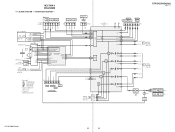
SECTION 4 DIAGRAMS 4-1. TUNER/AUDIO SECTION - BLOCK DIAGRAM - DG600 J400(DG600) J402(DG500) AUX SA-CD/CD MD/TAPE IN IN OUT L RL R L R -5 -6 -3 -4 -1 -2 MD/TAPE DVD AUDIO IN IN LRLR -3 -4 J403 -1 -2 VIDEO 3 IN/ PORTABLE AV IN AUDIO LR -2 -3 J298(2/2) DIR FUNCTION SELECT IC401 R-CH R-CH R-CH R-CH R-CH R-CH DG600:US,CND MODEL XM... MULTI CH IN 46 22 28 32 30 34 SEL 36 SW 38 60 MCU 59 I/F L SEL SL SEL 10 13 12 17 R-CH 11 R-CH 14 R-CH R-CH C SEL SW SEL SBL SEL DIGITAL SECTION B (Page 16) SBL OUT SW OUT C OUT SL OUT L OUT 54 56 51 52 49 STR-DG500...
SECTION 4 DIAGRAMS 4-1. TUNER/AUDIO SECTION - BLOCK DIAGRAM - DG600 J400(DG600) J402(DG500) AUX SA-CD/CD MD/TAPE IN IN OUT L RL R L R -5 -6 -3 -4 -1 -2 MD/TAPE DVD AUDIO IN IN LRLR -3 -4 J403 -1 -2 VIDEO 3 IN/ PORTABLE AV IN AUDIO LR -2 -3 J298(2/2) DIR FUNCTION SELECT IC401 R-CH R-CH R-CH R-CH R-CH R-CH DG600:US,CND MODEL XM... MULTI CH IN 46 22 28 32 30 34 SEL 36 SW 38 60 MCU 59 I/F L SEL SL SEL 10 13 12 17 R-CH 11 R-CH 14 R-CH R-CH C SEL SW SEL SBL SEL DIGITAL SECTION B (Page 16) SBL OUT SW OUT C OUT SL OUT L OUT 54 56 51 52 49 STR-DG500...
Service Manual
Page 16
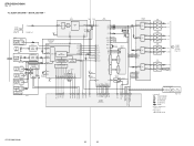
...SHAPER 2 IC1103 WAVE 3 SHAPER 2 SELECTOR IC1302 3 7 5 6 4 8 AB 14 2 VIDEO 3 IN/ PORTABLE AV IN DG600 ADC IC1401 DG600 DG500 DSP IC1501 1 L IN ADC LPF AUDIO I/F DOUT 15 18 SDI1 +5V-2 A.5V 16 SYS CLK RST LRCK 13...RECEIVER IC1301 DOUT 2 DIN2 5 SDIN 8 DIN1 4 INPUT DIN0 3 DATA DEMODULATOR Pa,Pb DETECTION C bit DETECTION MICROPROCESSOR I/F XMCK 20 AUDIO 24 CKOUT 13 BCK 14 LRCK 15 DATAO 16 LOCK ERROR DETECTION 34 21 XOUT DG500... to same as L-ch. • Abbreviation CND: Canadian model (Page 18) STR-DG500/DG600 16 16 STR-DG500/DG600 Ver. 1.1 4-2. DIGITAL SECTION -
...SHAPER 2 IC1103 WAVE 3 SHAPER 2 SELECTOR IC1302 3 7 5 6 4 8 AB 14 2 VIDEO 3 IN/ PORTABLE AV IN DG600 ADC IC1401 DG600 DG500 DSP IC1501 1 L IN ADC LPF AUDIO I/F DOUT 15 18 SDI1 +5V-2 A.5V 16 SYS CLK RST LRCK 13...RECEIVER IC1301 DOUT 2 DIN2 5 SDIN 8 DIN1 4 INPUT DIN0 3 DATA DEMODULATOR Pa,Pb DETECTION C bit DETECTION MICROPROCESSOR I/F XMCK 20 AUDIO 24 CKOUT 13 BCK 14 LRCK 15 DATAO 16 LOCK ERROR DETECTION 34 21 XOUT DG500... to same as L-ch. • Abbreviation CND: Canadian model (Page 18) STR-DG500/DG600 16 16 STR-DG500/DG600 Ver. 1.1 4-2. DIGITAL SECTION -

Service Manual
Page 17
...) PR/CR/R-Y -6 COMPONENT VIDEO -1 Y DVD IN PB/CB/B-Y -2 (ASSIGNABLE) -3 PR/CR/R-Y VIDEO 1 VIDEO 2 DVD -1 J201 (1/2) VIDEO IN -2 J200 (1/2) VIDEO IN -1 VIDEO IN VIDEO 3 IN/ PORTABLE AV IN J298 (1/2) -1 VIDEO DG600 VIDEO 1 -2 S-VIDEO IN J253 (1/2) YG C G J252 (1/2) -1 YG DVD S-VIDEO IN C G VIDEO 2 -2 S-VIDEO IN J252 (2/2) YG C G DG600 COMPONENT VIDEO SELECT IC304 3 CH1... model E2 : 120V AC area in E model MY : Malaysia model SP : Singapore model TH : Thai model SW2 SW2 SW5 SW1 SW4 SW3 OR D251,252 STR-DG500/DG600 17 17 STR-DG500/DG600 Ver. 1.1 4-3.
...) PR/CR/R-Y -6 COMPONENT VIDEO -1 Y DVD IN PB/CB/B-Y -2 (ASSIGNABLE) -3 PR/CR/R-Y VIDEO 1 VIDEO 2 DVD -1 J201 (1/2) VIDEO IN -2 J200 (1/2) VIDEO IN -1 VIDEO IN VIDEO 3 IN/ PORTABLE AV IN J298 (1/2) -1 VIDEO DG600 VIDEO 1 -2 S-VIDEO IN J253 (1/2) YG C G J252 (1/2) -1 YG DVD S-VIDEO IN C G VIDEO 2 -2 S-VIDEO IN J252 (2/2) YG C G DG600 COMPONENT VIDEO SELECT IC304 3 CH1... model E2 : 120V AC area in E model MY : Malaysia model SP : Singapore model TH : Thai model SW2 SW2 SW5 SW1 SW4 SW3 OR D251,252 STR-DG500/DG600 17 17 STR-DG500/DG600 Ver. 1.1 4-3.


