
Service Manual
Page 2
...MENTS PUBLIÉS PAR SONY. All preset stations will be measured by means of three methods. 1. Leakage current can change the tuning scale. Nearly all exposed metal parts to 9 kHz or 10 kHz. Check leakage as the Simpson 229 or RCA WT-540A. STR-DE197 AM tuner section Tuning ... you change the AM tuning scale to any AM station, turn off the receiver. SAFETY-RELATED COMPONENT WARNING!! COMPONENTS IDENTIFIED BY MARK 0 OR DOTTED LINE WITH MARK 0 ON THE SCHEMATIC DIAGRAMS AND IN THE PARTS LIST ARE CRITICAL TO SAFE OPERATION. The Data Precision 245 digital multimeter is ...
...MENTS PUBLIÉS PAR SONY. All preset stations will be measured by means of three methods. 1. Leakage current can change the tuning scale. Nearly all exposed metal parts to 9 kHz or 10 kHz. Check leakage as the Simpson 229 or RCA WT-540A. STR-DE197 AM tuner section Tuning ... you change the AM tuning scale to any AM station, turn off the receiver. SAFETY-RELATED COMPONENT WARNING!! COMPONENTS IDENTIFIED BY MARK 0 OR DOTTED LINE WITH MARK 0 ON THE SCHEMATIC DIAGRAMS AND IN THE PARTS LIST ARE CRITICAL TO SAFE OPERATION. The Data Precision 245 digital multimeter is ...
Service Manual
Page 3
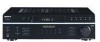
... Board 9 3. Printed Wiring Boards - Main Section 17 4-6. Schematic Diagram - Schematic Diagram - ELECTRICAL PARTS LIST 26 3 DISASSEMBLY 2-1. IC Pin Description 11 4-2. MODEL US AEP CND PART No. 4-253-299-0s 4-253-299-1s 4-253-299-3s • Abbreviation CND: Canadian model STR-DE197 TABLE OF CONTENTS 1. Circuit Boards Location 13 4-3. Panel Section 21 4-10. Case...
... Board 9 3. Printed Wiring Boards - Main Section 17 4-6. Schematic Diagram - Schematic Diagram - ELECTRICAL PARTS LIST 26 3 DISASSEMBLY 2-1. IC Pin Description 11 4-2. MODEL US AEP CND PART No. 4-253-299-0s 4-253-299-1s 4-253-299-3s • Abbreviation CND: Canadian model STR-DE197 TABLE OF CONTENTS 1. Circuit Boards Location 13 4-3. Panel Section 21 4-10. Case...
Service Manual
Page 14
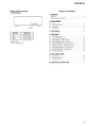
... All resistors are in µF unless otherwise noted. (p: pF) 50 WV or less are not indicated except for printed wiring boards: • X : parts extracted from the component side. • f : internal component. • : Pattern from the side which enables seeing. • Abbreviation CND : Canadian model...normal production tolerances. • Waveforms are taken with part number specified. Voltage variations may be noted due to ground under no mark : FM • Voltages are taken with mark 0 are critical for safety. STR-DE197 THIS NOTE IS COMMON FOR PRINTED WIRING BOARDS AND...
... All resistors are in µF unless otherwise noted. (p: pF) 50 WV or less are not indicated except for printed wiring boards: • X : parts extracted from the component side. • f : internal component. • : Pattern from the side which enables seeing. • Abbreviation CND : Canadian model...normal production tolerances. • Waveforms are taken with part number specified. Voltage variations may be noted due to ground under no mark : FM • Voltages are taken with mark 0 are critical for safety. STR-DE197 THIS NOTE IS COMMON FOR PRINTED WIRING BOARDS AND...

Service Manual
Page 23
...233;. No. 3 4 5 #1 Part No. No. 1 1 1 2 2 Part No. SECTION 5 EXPLODED VIEWS • Color Indication of this parts list. • Abbreviation CND : Canadian model 5-1. CASE SECTION 2 STR-DE197 Ver. 1.2 The components identified by mark 0 or dotted line with part number specified. Description X-4953-448-1 FOOT... have some difference from the original one. NOTE: • The mechanical parts with no reference number in the last of Appearance Parts Example : KNOB, BALANCE (WHITE) ... (RED) R R Parts Color Cabinet's Color • Accessories are given in the exploded views are...
...233;. No. 3 4 5 #1 Part No. No. 1 1 1 2 2 Part No. SECTION 5 EXPLODED VIEWS • Color Indication of this parts list. • Abbreviation CND : Canadian model 5-1. CASE SECTION 2 STR-DE197 Ver. 1.2 The components identified by mark 0 or dotted line with part number specified. Description X-4953-448-1 FOOT... have some difference from the original one. NOTE: • The mechanical parts with no reference number in the last of Appearance Parts Example : KNOB, BALANCE (WHITE) ... (RED) R R Parts Color Cabinet's Color • Accessories are given in the exploded views are...

Service Manual
Page 24
No. 51 51 51 51 51 52 53 53 53 Part No. PHONE board) 57 58 54 56 54 FL201 54 59 54 not supplied (VOLUME board) not supplied (FUNCTION KEY board) 51 53 supplied with ...) (SILVER) KNOB (VOL) (SILVER:for Hair-line Finish) Ref. No. 54 55 56 56 * 57 * 58 59 59 FL201 Part No. FRONT PANEL SECTION 55 54 not supplied 54 (POWER board) not supplied (H. STR-DE197 Ver. 1.2 5-2. Description Remark 4-951-620-01 SCREW (2.6X8), +BVTP 1-773-026-11 WIRE (FLAT TYPE) (15 CORE) A-4751...
No. 51 51 51 51 51 52 53 53 53 Part No. PHONE board) 57 58 54 56 54 FL201 54 59 54 not supplied (VOLUME board) not supplied (FUNCTION KEY board) 51 53 supplied with ...) (SILVER) KNOB (VOL) (SILVER:for Hair-line Finish) Ref. No. 54 55 56 56 * 57 * 58 59 59 FL201 Part No. FRONT PANEL SECTION 55 54 not supplied 54 (POWER board) not supplied (H. STR-DE197 Ver. 1.2 5-2. Description Remark 4-951-620-01 SCREW (2.6X8), +BVTP 1-773-026-11 WIRE (FLAT TYPE) (15 CORE) A-4751...

Service Manual
Page 25
... 3X8 TYPE2 IT-3 25 No. 0 F902 0 F902 Q703 Q704 Q753 Q754 0 T901 0 T901 TN1 TN1 #1 Part No. Ne les remplacer que par une piéce portant le numéro spécifié. STR-DE197 5-3. Description Remark 4-249-675-01 +BV SUMITITE S 4X6 ROUND 3-970-608-01 SUMITITE (B3), +BV A-4751... 1-533-469-12 FUSE, GLASS TUBE (DIA.5) (T2.5AL/250V) (AEP) Ref. No. 101 102 103 103 104 0 105 0 105 * 106 107 107 0 F901 0 F901 Part No. CHASSIS SECTION 102 101 101 T901 #1 F901 102 103 102 F902 Q754 Q753 102 104 Q704 Q703 #1 #1 105 #1 106 #1 not supplied (AC OUTLET board...
... 3X8 TYPE2 IT-3 25 No. 0 F902 0 F902 Q703 Q704 Q753 Q754 0 T901 0 T901 TN1 TN1 #1 Part No. Ne les remplacer que par une piéce portant le numéro spécifié. STR-DE197 5-3. Description Remark 4-249-675-01 +BV SUMITITE S 4X6 ROUND 3-970-608-01 SUMITITE (B3), +BV A-4751... 1-533-469-12 FUSE, GLASS TUBE (DIA.5) (T2.5AL/250V) (AEP) Ref. No. 101 102 103 103 104 0 105 0 105 * 106 107 107 0 F901 0 F901 Part No. CHASSIS SECTION 102 101 101 T901 #1 F901 102 103 102 F902 Q754 Q753 102 104 Q704 Q703 #1 #1 105 #1 106 #1 not supplied (AC OUTLET board...
Service Manual
Page 26
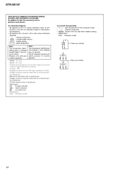
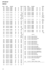
... 1-249-429-11 CARBON R239 1-249-429-11 CARBON 100 5% 1/4W 100 5% 1/4W 100 5% 1/4W (AEP) 10K 5% 1/4W 10K 5% 1/4W 26 Part No. uPC.. : µPC.. STR-DE197 SECTION 6 AC OUTLET DISPLAY ELECTRICAL PARTS LIST NOTE: • Due to standardization, replacements in ohms. METAL:Metal-film resistor. Some delay should be different from the...
... 1-249-429-11 CARBON R239 1-249-429-11 CARBON 100 5% 1/4W 100 5% 1/4W 100 5% 1/4W (AEP) 10K 5% 1/4W 10K 5% 1/4W 26 Part No. uPC.. : µPC.. STR-DE197 SECTION 6 AC OUTLET DISPLAY ELECTRICAL PARTS LIST NOTE: • Due to standardization, replacements in ohms. METAL:Metal-film resistor. Some delay should be different from the...

Service Manual
Page 27
...S236 1-771-410-21 SWITCH, TACTILE (VIDEO 1) 5% 1/4W 5% 1/4W 5% 1/4W 5% 1/4W 5% 1/4W 5% 1/4W 5% 1/4W 5% 1/4W 5% 1/4W 27 R240 R241 R242 Part No. Description 1-249-429-11 CARBON 1-247-879-11 CARBON 1-247-807-31 CARBON R243 1-249-429-11 CARBON R244 1-249-429-11 CARBON R245...11 CARBON CARBON CARBON CARBON CARBON R308 R309 R310 1-247-871-11 CARBON 1-247-871-11 CARBON 1-247-871-11 CARBON STR-DE197 DISPLAY FUNCTION KEY 10K 100K 100 10K 10K 10K 10K 10K 10K 10K 1M 470 100 10K 10K 47K 47K 1K 2.... 10K 10K 10K 10K 47 4.7K 100 100 100 47K 47K 47K 47K 47K 47K Remark Ref. Part No. No.
...S236 1-771-410-21 SWITCH, TACTILE (VIDEO 1) 5% 1/4W 5% 1/4W 5% 1/4W 5% 1/4W 5% 1/4W 5% 1/4W 5% 1/4W 5% 1/4W 5% 1/4W 27 R240 R241 R242 Part No. Description 1-249-429-11 CARBON 1-247-879-11 CARBON 1-247-807-31 CARBON R243 1-249-429-11 CARBON R244 1-249-429-11 CARBON R245...11 CARBON CARBON CARBON CARBON CARBON R308 R309 R310 1-247-871-11 CARBON 1-247-871-11 CARBON 1-247-871-11 CARBON STR-DE197 DISPLAY FUNCTION KEY 10K 100K 100 10K 10K 10K 10K 10K 10K 10K 1M 470 100 10K 10K 47K 47K 1K 2.... 10K 10K 10K 10K 47 4.7K 100 100 100 47K 47K 47K 47K 47K 47K Remark Ref. Part No. No.

Service Manual
Page 31
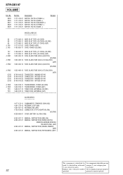
STR-DE197 MAIN POWER VOLUME Ref. Description R787 1-247-847-11 CARBON 4.7K R788 1-249-427-11 CARBON 6.8K... 1-249-393-11 CARBON 10 RR752 1-249-393-11 CARBON 10 < RELAY > RY781 1-755-416-12 RELAY RY782 1-755-416-12 RELAY Remark Ref. Part No. Description 5% 1/4W 5% 1/4W 5% 1/4W 5% 1/4W 5% 1/4W RY783 1-755-416-12 RELAY RY981 1-755-013-11 RELAY 0 RY982 1-755...-21 SWITCH, TACTILE (BALANCE R) The components identified by Les composants identifiés par une mark 0 or dotted line with part number Ne les remplacer que par une piéce specified. portant le numéro spécifié...
STR-DE197 MAIN POWER VOLUME Ref. Description R787 1-247-847-11 CARBON 4.7K R788 1-249-427-11 CARBON 6.8K... 1-249-393-11 CARBON 10 RR752 1-249-393-11 CARBON 10 < RELAY > RY781 1-755-416-12 RELAY RY782 1-755-416-12 RELAY Remark Ref. Part No. Description 5% 1/4W 5% 1/4W 5% 1/4W 5% 1/4W 5% 1/4W RY783 1-755-416-12 RELAY RY981 1-755-013-11 RELAY 0 RY982 1-755...-21 SWITCH, TACTILE (BALANCE R) The components identified by Les composants identifiés par une mark 0 or dotted line with part number Ne les remplacer que par une piéce specified. portant le numéro spécifié...
Service Manual
Page 32
Part No. la sécurité. 32 Replace only with mark marque 0 sont critiques pour 0 are critical for RM...) (AEP) MANUAL, INSTRUCTION (PORTUGUESE) (AEP) The components identified by Les composants identifiés par une mark 0 or dotted line with part number Ne les remplacer que par une piéce specified. Description Remark S225 1-771-410-21 SWITCH, TACTILE (TREBLE +) S226 1-771-410...U185) ANTENNA, LOOP (AM) ANTENNA (FM) (AEP) CONNECTOR (F TYPE ADAPTOR) (FM) (US,CND) COVER, BATTERY (for safety. No. STR-DE197 VOLUME Ref. portant le numéro spécifié.
Part No. la sécurité. 32 Replace only with mark marque 0 sont critiques pour 0 are critical for RM...) (AEP) MANUAL, INSTRUCTION (PORTUGUESE) (AEP) The components identified by Les composants identifiés par une mark 0 or dotted line with part number Ne les remplacer que par une piéce specified. Description Remark S225 1-771-410-21 SWITCH, TACTILE (TREBLE +) S226 1-771-410...U185) ANTENNA, LOOP (AM) ANTENNA (FM) (AEP) CONNECTOR (F TYPE ADAPTOR) (FM) (US,CND) COVER, BATTERY (for safety. No. STR-DE197 VOLUME Ref. portant le numéro spécifié.

Service Manual
Page 33
When performing service and inspection, check the part number of new type, and changed parts list are described in this supplement with the service manual. MAIN BOARD Part No. Former : 1-861-592-11 New : 1-871-790-11 - DISPLAY BOARD Part No. Printed wiring board and schematic diagram of... the MAIN, DISPLAY, VOLUME, H.PHONE, POWER, FUNCTION KEY and AC OUTLET boards. DISPLAY BOARD (COMPONENT SIDE) - STR-DE197 SERVICE MANUAL Ver. 1.3 2006. 09 US Model Canadian Model AEP ...
When performing service and inspection, check the part number of new type, and changed parts list are described in this supplement with the service manual. MAIN BOARD Part No. Former : 1-861-592-11 New : 1-871-790-11 - DISPLAY BOARD Part No. Printed wiring board and schematic diagram of... the MAIN, DISPLAY, VOLUME, H.PHONE, POWER, FUNCTION KEY and AC OUTLET boards. DISPLAY BOARD (COMPONENT SIDE) - STR-DE197 SERVICE MANUAL Ver. 1.3 2006. 09 US Model Canadian Model AEP ...

Service Manual
Page 35
... IGOUTL VOLINL IGOUTR VOLINR BASSR1 BASSR2 BASSL1 • Waveform 1 IC201 eg (X2) 4.19 MHz 2V/DIV, 0.2µsec/DIV 3.6 Vp-p STR-DE197 3 3 TABLE OF CONTENTS 1. no -signal (detuned) conditions. C Q These are taken with a VOM (Input impedance 10 MΩ). Schematic... : Pattern from the side which enables seeing. • Abbreviation CND : Canadian model. • (( )): Page of Supplement-1. Electrical Parts List 9 THIS NOTE IS COMMON FOR PRINTED WIRING BOARDS AND SCHEMATIC DIAGRAMS. (In addition to normal production tolerances. • Waveforms are omitted...
... IGOUTL VOLINL IGOUTR VOLINR BASSR1 BASSR2 BASSL1 • Waveform 1 IC201 eg (X2) 4.19 MHz 2V/DIV, 0.2µsec/DIV 3.6 Vp-p STR-DE197 3 3 TABLE OF CONTENTS 1. no -signal (detuned) conditions. C Q These are taken with a VOM (Input impedance 10 MΩ). Schematic... : Pattern from the side which enables seeing. • Abbreviation CND : Canadian model. • (( )): Page of Supplement-1. Electrical Parts List 9 THIS NOTE IS COMMON FOR PRINTED WIRING BOARDS AND SCHEMATIC DIAGRAMS. (In addition to normal production tolerances. • Waveforms are omitted...

Service Manual
Page 41
... used on the set. • -XX and -X mean standardized parts, so they are in ohms. METAL:Metal-film resistor. uPD.. : µPD.. • CAPACITORS uF : µF • COILS uH : µH STR-DE197 Ver. 1.5 AC OUTLET DISPLAY The components identified by reference number, ...please include the board. Replace only with mark 0 are critical for safety. CNS5 D201 D202 D203 D204 FL201 Part No. Description 1-784-776-11 CONNECTOR, FFC 15P Remark < DIODE...
... used on the set. • -XX and -X mean standardized parts, so they are in ohms. METAL:Metal-film resistor. uPD.. : µPD.. • CAPACITORS uF : µF • COILS uH : µH STR-DE197 Ver. 1.5 AC OUTLET DISPLAY The components identified by reference number, ...please include the board. Replace only with mark 0 are critical for safety. CNS5 D201 D202 D203 D204 FL201 Part No. Description 1-784-776-11 CONNECTOR, FFC 15P Remark < DIODE...
Service Manual
Page 42
... 10K 10K 1M 470 100 10K 10K 47K 47K 1K 2.2K 47K 2.2K 100 1K 2.2K 2.2K 4.7K 10K 22K 47K 1K 2.2K Remark Ref. STR-DE197 DISPLAY Ref. No. R222 R223 R224 R225 R226 Part No. No. Part No.
... 10K 10K 1M 470 100 10K 10K 47K 47K 1K 2.2K 47K 2.2K 100 1K 2.2K 2.2K 4.7K 10K 22K 47K 1K 2.2K Remark Ref. STR-DE197 DISPLAY Ref. No. R222 R223 R224 R225 R226 Part No. No. Part No.

Service Manual
Page 43
Part No. Description FUNCTION KEY BOARD Remark < RESISTOR > R256 R257 R258 R259 R260 1-247-831-11 1-249-421-11 1-249-421-11 1-247-847-11 1-...314-21 JACK (PHONES A-1212-652-A MAIN BOARD, COMPLETE (US,CND) A-1212-659-A MAIN BOARD, COMPLETE (AEP) 1-533-217-41 HOLDER, FUSE < CAPACITOR > Ref. No. STR-DE197 Ver. 1.5 FUNCTION KEY H.PHONE MAIN Ref. No. Description 1-126-964-11 1-126-961-11 1-126-964-11 1-126-963-11 1-136-167-00 ELECT ELECT...C470 C474 C475 C476 C483 C484 C485 C486 C487 C490 C602 C603 C604 C605 C606 C607 C608 C652 C653 C654 C655 C656 C657 C658 C701 Part No.
Part No. Description FUNCTION KEY BOARD Remark < RESISTOR > R256 R257 R258 R259 R260 1-247-831-11 1-249-421-11 1-249-421-11 1-247-847-11 1-...314-21 JACK (PHONES A-1212-652-A MAIN BOARD, COMPLETE (US,CND) A-1212-659-A MAIN BOARD, COMPLETE (AEP) 1-533-217-41 HOLDER, FUSE < CAPACITOR > Ref. No. STR-DE197 Ver. 1.5 FUNCTION KEY H.PHONE MAIN Ref. No. Description 1-126-964-11 1-126-961-11 1-126-964-11 1-126-963-11 1-136-167-00 ELECT ELECT...C470 C474 C475 C476 C483 C484 C485 C486 C487 C490 C602 C603 C604 C605 C606 C607 C608 C652 C653 C654 C655 C656 C657 C658 C701 Part No.
Service Manual
Page 49
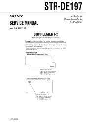
STR-DE197 SERVICE MANUAL Ver. 1.4 2007. 03 US Model Canadian Model AEP Model SUPPLEMENT-2 File this Supplement-2. Printed wiring board and schematic diagram of the MAIN and DISPLAY boards. MAIN BOARD Part No. 1-861-592-1 : Service Manual 1-871-790-1 :Supplement-1 1-861-592-2 :Supplement-2 - DISCRIMINATION - When performing service and inspection, check the part... number of new type, and changed parts list are described in this supplement with the service manual. MAIN BOARD (COMPONENT SIDE) - DISPLAY BOARD (COMPONENT SIDE) - DISPLAY BOARD Part No. 1-861...
STR-DE197 SERVICE MANUAL Ver. 1.4 2007. 03 US Model Canadian Model AEP Model SUPPLEMENT-2 File this Supplement-2. Printed wiring board and schematic diagram of the MAIN and DISPLAY boards. MAIN BOARD Part No. 1-861-592-1 : Service Manual 1-871-790-1 :Supplement-1 1-861-592-2 :Supplement-2 - DISCRIMINATION - When performing service and inspection, check the part... number of new type, and changed parts list are described in this supplement with the service manual. MAIN BOARD (COMPONENT SIDE) - DISPLAY BOARD (COMPONENT SIDE) - DISPLAY BOARD Part No. 1-861...
Service Manual
Page 50
Schematic Diagram -Main Section (1/2 5 3. Printed Wiring Boards -Panel Section 7 5. Schematic Diagram -Main Section (2/2 6 4. STR-DE197 TABLE OF CONTENTS 1. Schematic Diagram -Panel Section 8 6. Electrical Parts List 9 2 Printed Wiring Boards -Main Section 4 2.
Schematic Diagram -Main Section (1/2 5 3. Printed Wiring Boards -Panel Section 7 5. Schematic Diagram -Main Section (2/2 6 4. STR-DE197 TABLE OF CONTENTS 1. Schematic Diagram -Panel Section 8 6. Electrical Parts List 9 2 Printed Wiring Boards -Main Section 4 2.

Service Manual
Page 51
.... • All resistors are in µF unless otherwise noted. (p: pF) 50 WV or less are not indicated except for printed wiring boards: • X : parts extracted from the component side. • f : internal component. • : Pattern from the side which enables seeing. • (( )): Page of Supplement-2. C ...; A : B+ Line. • B : B- Note: The components identified by mark 0 or dotted line with mark 0 are critical for safety. STR-DE197 • IC Block Diagram IC402 R2S15904SP INR4 LOUT ROUT AGND VCC REFIN DATA CLK DGND TRER TREL NC NC BASSL2 28 27 26 INPUT SELECTOR...
.... • All resistors are in µF unless otherwise noted. (p: pF) 50 WV or less are not indicated except for printed wiring boards: • X : parts extracted from the component side. • f : internal component. • : Pattern from the side which enables seeing. • (( )): Page of Supplement-2. C ...; A : B+ Line. • B : B- Note: The components identified by mark 0 or dotted line with mark 0 are critical for safety. STR-DE197 • IC Block Diagram IC402 R2S15904SP INR4 LOUT ROUT AGND VCC REFIN DATA CLK DGND TRER TREL NC NC BASSL2 28 27 26 INPUT SELECTOR...

Service Manual
Page 57
...écifié. Ref. No. uPB.. : µPB.. uPD.. : µPD.. • CAPACITORS uF : µF • COILS uH : µH STR-DE197 DISPLAY The components identified by reference number, please include the board. No. Part No. Description < JUMPER RESISTOR > JR201 1-216-296-11 SHORT CHIP 0 JR202 1-216-296-11 SHORT CHIP 0 JR203 1-216-296...
...écifié. Ref. No. uPB.. : µPB.. uPD.. : µPD.. • CAPACITORS uF : µF • COILS uH : µH STR-DE197 DISPLAY The components identified by reference number, please include the board. No. Part No. Description < JUMPER RESISTOR > JR201 1-216-296-11 SHORT CHIP 0 JR202 1-216-296-11 SHORT CHIP 0 JR203 1-216-296...

Service Manual
Page 58
STR-DE197 DISPLAY MAIN Ref. Part No. Description 1-249-389-11 1-249-389-11 1-247-807-31 1-249-393-11 1-247-807-31 CARBON CARBON CARBON CARBON CARBON R232 R233 R234 ...% 4.7uF 20% 4.7uF 20% 50V 100V 50V 50V 50V C422 1-126-963-11 ELECT 4.7uF 20% 50V 10 No. No. R227 R228 R229 R230 R231 Part No.
STR-DE197 DISPLAY MAIN Ref. Part No. Description 1-249-389-11 1-249-389-11 1-247-807-31 1-249-393-11 1-247-807-31 CARBON CARBON CARBON CARBON CARBON R232 R233 R234 ...% 4.7uF 20% 4.7uF 20% 50V 100V 50V 50V 50V C422 1-126-963-11 ELECT 4.7uF 20% 50V 10 No. No. R227 R228 R229 R230 R231 Part No.

