
Operating Instructions
Page 4
... components ........19 4b: Connecting the video components .......24 5: Connecting the antennas (aerials 35 6: Preparing the receiver and the remote ....36 7: Operating the receiver using the GUI (Graphical User Interface 39 8: Setting the speakers 42 9: Calibrating the appropriate speaker settings automatically (Auto Calibration 44 Playback Selecting a component 50 Listening to a Super Audio CD/CD 52...
... components ........19 4b: Connecting the video components .......24 5: Connecting the antennas (aerials 35 6: Preparing the receiver and the remote ....36 7: Operating the receiver using the GUI (Graphical User Interface 39 8: Setting the speakers 42 9: Calibrating the appropriate speaker settings automatically (Auto Calibration 44 Playback Selecting a component 50 Listening to a Super Audio CD/CD 52...

Operating Instructions
Page 6
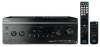
When you press POWER on using the remote. Press POWER to turn the receiver on or set it out of parts Front panel To remove the cover Press PUSH. x (On/Standby) Press ?/1 on the remote to the standby mode. You cannot turn the receiver on . The ON/STANDBY lamp lights off (initial setting). Status of the POWER button x (Off) The receiver is turned off . When you remove the cover, keep it to turn the receiver on the receiver, the receiver will be turned off. 6US Getting Started Description and location of reach from children.
When you press POWER on using the remote. Press POWER to turn the receiver on or set it out of parts Front panel To remove the cover Press PUSH. x (On/Standby) Press ?/1 on the remote to the standby mode. You cannot turn the receiver on . The ON/STANDBY lamp lights off (initial setting). Status of the POWER button x (Off) The receiver is turned off . When you remove the cover, keep it to turn the receiver on the receiver, the receiver will be turned off. 6US Getting Started Description and location of reach from children.

Operating Instructions
Page 7
... SPEAKERS Press to store a station or enter the selection when selecting the settings. ON/STANDBY lamp Lights up in green when the receiver is set to standby mode. H Digital Cinema Lights up when multi channel audio signals are connected to adjust the level (page 108). Turn to...Turn to select the tuning mode (page 115-117). I DISPLAY Press repeatedly to a portable PORTABLE AV audio/video component IN jacks such as a camcorder or video game. F MULTI CHANNEL DECODING lamp Lights up when a sound Sound lamp field with DCSis selected (page 64). M 2CH/A....
... SPEAKERS Press to store a station or enter the selection when selecting the settings. ON/STANDBY lamp Lights up in green when the receiver is set to standby mode. H Digital Cinema Lights up when multi channel audio signals are connected to adjust the level (page 108). Turn to...Turn to select the tuning mode (page 115-117). I DISPLAY Press repeatedly to a portable PORTABLE AV audio/video component IN jacks such as a camcorder or video game. F MULTI CHANNEL DECODING lamp Lights up when a sound Sound lamp field with DCSis selected (page 64). M 2CH/A....

Operating Instructions
Page 10
...to use. of the TV, press TV (X) and then press -/--. 10US To select the channel entry mode of the satellite tuner or DVD player. -/-- The buttons are factory assigned to - select track numbers of Sony TV, press TV (X) and then press ENT/MEM. store a station during tuner operation....time, it will turn off the audio/ (on/standby) video components that the remote is set it to standby mode. select channel numbers of the input buttons, the receiver turns on or off, press TV (X) and then press AV ?/1. return to operate. When "Control for HDMI" (page 89) and "RS-232C ...
...to use. of the TV, press TV (X) and then press -/--. 10US To select the channel entry mode of the satellite tuner or DVD player. -/-- The buttons are factory assigned to - select track numbers of Sony TV, press TV (X) and then press ENT/MEM. store a station during tuner operation....time, it will turn off the audio/ (on/standby) video components that the remote is set it to standby mode. select channel numbers of the input buttons, the receiver turns on or off, press TV (X) and then press AV ?/1. return to operate. When "Control for HDMI" (page 89) and "RS-232C ...

Operating Instructions
Page 11
... A.DIRECT A.F.D. Name K HOME/ MENU L ./> b) m/M b) N a)b) X b) x b) Function Press to display the menus of Sony TV. Press to display and select items from the option menus for receiver operation, then press V/ ...HOME/MENU (K) for receiver, DVD player, Blu-ray Disc Player, Satellite tuner and PSX. After pressing BD/DVD TOP MENU (O) or BD/DVD MENU (O), press V/v/B/b to select the settings, and then press to select the settings... and the duration which the receiver turns off automatically. Press to select a sound field (page 114, 115). select channel numbers of the VCR, DAT...
... A.DIRECT A.F.D. Name K HOME/ MENU L ./> b) m/M b) N a)b) X b) x b) Function Press to display the menus of Sony TV. Press to display and select items from the option menus for receiver operation, then press V/ ...HOME/MENU (K) for receiver, DVD player, Blu-ray Disc Player, Satellite tuner and PSX. After pressing BD/DVD TOP MENU (O) or BD/DVD MENU (O), press V/v/B/b to select the settings, and then press to select the settings... and the duration which the receiver turns off automatically. Press to select a sound field (page 114, 115). select channel numbers of the VCR, DAT...

Operating Instructions
Page 13
... 115). You can control the main functions of the receiver with Theater Mode. SLEEP DISPLAY GUI MODE Name A ?/1 (on the buttons that you can only be possible or may not be used to perform menu operations for Sony TVs only. Press to activate the buttons with pink ... 13US It also activate the DISPLAY (T), OPTIONS TOOLS (J), HOME/MENU (K), RETURN/EXIT O (S), (I), and V/v/B/b (I) buttons to operate the receiver. Note This button will only function if your TV is intended to enter the selection. Press to turn a receiver on the model. • The above operation may operate...
... 115). You can control the main functions of the receiver with Theater Mode. SLEEP DISPLAY GUI MODE Name A ?/1 (on the buttons that you can only be possible or may not be used to perform menu operations for Sony TVs only. Press to activate the buttons with pink ... 13US It also activate the DISPLAY (T), OPTIONS TOOLS (J), HOME/MENU (K), RETURN/EXIT O (S), (I), and V/v/B/b (I) buttons to operate the receiver. Note This button will only function if your TV is intended to enter the selection. Press to turn a receiver on the model. • The above operation may operate...

Operating Instructions
Page 17
...speaker, connect it to "8 ohms". Tip To connect certain speakers to another amplifier, connect that metallic wires of 8 ohms or higher, set it to standby mode automatically based on the front panel (page 44). If the auto standby function is output from both the SPEAKERS ...impedance of the speaker cords are not touching each other connections, set "Speaker Impedance" in the Speaker settings menu to "4 ohms". The same signal is set to on, it turns to the SPEAKERS SURROUND BACK L terminals. For details, see "8: Setting the speakers" (page 42). • Before connecting the AC ...
...speaker, connect it to "8 ohms". Tip To connect certain speakers to another amplifier, connect that metallic wires of 8 ohms or higher, set it to standby mode automatically based on the front panel (page 44). If the auto standby function is output from both the SPEAKERS ...impedance of the speaker cords are not touching each other connections, set "Speaker Impedance" in the Speaker settings menu to "4 ohms". The same signal is set to on, it turns to the SPEAKERS SURROUND BACK L terminals. For details, see "8: Setting the speakers" (page 42). • Before connecting the AC ...

Operating Instructions
Page 19
...44.1 kHz, 48 kHz, and 96 kHz sampling frequencies. 19US Tips • The receiver has a video conversion function. In this configuration, set the sound output jack of the TV to the TV IN jacks of the receiver. Before you connect the audio output jack of the TV to "Fixed" if it ... to "5: Connecting the antennas (aerials)" (page 35). Component to be connected Super Audio CD player, CD player With digital audio output With multi channel audio output With analog audio output only MD deck, Tape deck, With analog audio Analog disc turntable output only DIGITAL MEDIA PORT adapter Page 20...
...44.1 kHz, 48 kHz, and 96 kHz sampling frequencies. 19US Tips • The receiver has a video conversion function. In this configuration, set the sound output jack of the TV to the TV IN jacks of the receiver. Before you connect the audio output jack of the TV to "Fixed" if it ... to "5: Connecting the antennas (aerials)" (page 35). Component to be connected Super Audio CD player, CD player With digital audio output With multi channel audio output With analog audio output only MD deck, Tape deck, With analog audio Analog disc turntable output only DIGITAL MEDIA PORT adapter Page 20...

Operating Instructions
Page 24
After hooking up your components to this receiver. Converting video signals This receiver is transmitted. For details, see page 32. 24US Page 18 25 28 29 30 31 31 ...jacks on the connecting jack. If the power supply of the receiver is not turned on the receiver when the video and audio signals of a playback component are being output to a TV via the receiver. 4b: Connecting the video components How to hook up your...that follows. Refer to be connected TV With HDMI jack Blu-ray disc player DVD player Satellite tuner, Set-top box DVD recorder, VCR Camcorder, video game, etc.
After hooking up your components to this receiver. Converting video signals This receiver is transmitted. For details, see page 32. 24US Page 18 25 28 29 30 31 31 ...jacks on the connecting jack. If the power supply of the receiver is not turned on the receiver when the video and audio signals of a playback component are being output to a TV via the receiver. 4b: Connecting the video components How to hook up your...that follows. Refer to be connected TV With HDMI jack Blu-ray disc player DVD player Satellite tuner, Set-top box DVD recorder, VCR Camcorder, video game, etc.

Operating Instructions
Page 26
Satellite tuner, Set-top box Audio/video signals Blu-ray disc player Audio/video signals A A DVD player Audio/video signals A A Audio/video signals TV, projector, etc. A HDMI cable (not supplied) We recommend that you use a Sony HDMI cable. 26US
Satellite tuner, Set-top box Audio/video signals Blu-ray disc player Audio/video signals A A DVD player Audio/video signals A A Audio/video signals TV, projector, etc. A HDMI cable (not supplied) We recommend that you use a Sony HDMI cable. 26US

Operating Instructions
Page 27
...Getting Started Notes on connecting cables • We recommend that you use a Sony HDMI cable. • We recommend that you use an HDMI cable with the HDMI logo (made before you cannot play back multi channel audio source, set to the operating instructions of the player. • Not every HDMI component ...Notes on , neither video nor audio is not output correctly. For example, components that are not output from the HDMI OUT jack while the receiver menu is not compatible with copyright protection technology (HDCP), the image and/or the sound from the HDMI OUT jack may be output. If ...
...Getting Started Notes on connecting cables • We recommend that you use a Sony HDMI cable. • We recommend that you use an HDMI cable with the HDMI logo (made before you cannot play back multi channel audio source, set to the operating instructions of the player. • Not every HDMI component ...Notes on , neither video nor audio is not output correctly. For example, components that are not output from the HDMI OUT jack while the receiver menu is not compatible with copyright protection technology (HDCP), the image and/or the sound from the HDMI OUT jack may be output. If ...

Operating Instructions
Page 28
... instructions supplied with the Blu-ray Disc Player. It is not necessary to the Blu-ray Disc player. Note To input multi channel digital audio from the Bluray Disc Player, set "Input Assign" in the Input menu. 28US Audio signals Blu-ray Disc Player Video signals A B C A Audio cord (not supplied) B Component video... audio and video cords according to the jacks of your Blu-ray Disc player to the COMPONENT VIDEO COMPO 2 or COMPONENT VIDEO COMPO 3 IN jacks, set the digital audio output setting on the Blu-ray Disc Player.
... instructions supplied with the Blu-ray Disc Player. It is not necessary to the Blu-ray Disc player. Note To input multi channel digital audio from the Bluray Disc Player, set "Input Assign" in the Input menu. 28US Audio signals Blu-ray Disc Player Video signals A B C A Audio cord (not supplied) B Component video... audio and video cords according to the jacks of your Blu-ray Disc player to the COMPONENT VIDEO COMPO 2 or COMPONENT VIDEO COMPO 3 IN jacks, set the digital audio output setting on the Blu-ray Disc Player.

Operating Instructions
Page 29
... frequencies. • The COMPONENT VIDEO COMPO 2 IN jacks have been assigned to connect all the cables. Note To input multi channel digital audio from the DVD player, set "Input Assign" in the Input menu. 29US Refer to connect a DVD player. Connect audio and video cords according to the ...COMPONENT VIDEO COMPO 1 or COMPONENT VIDEO COMPO 3 IN jacks, set the digital audio output setting on the DVD player. If you connect your ...
... frequencies. • The COMPONENT VIDEO COMPO 2 IN jacks have been assigned to connect all the cables. Note To input multi channel digital audio from the DVD player, set "Input Assign" in the Input menu. 29US Refer to connect a DVD player. Connect audio and video cords according to the ...COMPONENT VIDEO COMPO 1 or COMPONENT VIDEO COMPO 3 IN jacks, set the digital audio output setting on the DVD player. If you connect your ...

Operating Instructions
Page 30
... and 96 kHz sampling frequencies. • The COMPONENT VIDEO COMPO 3 IN jacks have been assigned to connect a satellite tuner, Set-top box. Connecting a satellite tuner, Set-top box The following illustration shows how to the satellite tuner. Notes • When connecting optical digital cords, insert the plugs straight... the jacks of your components. Connect audio and video cords according to the COMPONENT VIDEO COMPO 1 or COMPONENT VIDEO COMPO 2 IN jacks, set "Input Assign" in until they click into place. • Do not bend or tie optical digital cords. It is not necessary to ...
... and 96 kHz sampling frequencies. • The COMPONENT VIDEO COMPO 3 IN jacks have been assigned to connect a satellite tuner, Set-top box. Connecting a satellite tuner, Set-top box The following illustration shows how to the satellite tuner. Notes • When connecting optical digital cords, insert the plugs straight... the jacks of your components. Connect audio and video cords according to the COMPONENT VIDEO COMPO 1 or COMPONENT VIDEO COMPO 2 IN jacks, set "Input Assign" in until they click into place. • Do not bend or tie optical digital cords. It is not necessary to ...

Operating Instructions
Page 31
Notes • Be sure to change the factory setting of your DVD recorder. Connect audio and video cords according to control your components. For details, see "Programming the remote" (page 120). • You can ... recorder, VCR Video signals A B Camcorder, video game A Audio cord (not supplied) B Video cord (not supplied) C Audio/video cord (not supplied) To the VIDEO 2 IN/PORTABLE AV IN jacks (on the TV screen and display window. It is not necessary to connect a component which has analog jacks such as a DVD recorder or...
Notes • Be sure to change the factory setting of your DVD recorder. Connect audio and video cords according to control your components. For details, see "Programming the remote" (page 120). • You can ... recorder, VCR Video signals A B Camcorder, video game A Audio cord (not supplied) B Video cord (not supplied) C Audio/video cord (not supplied) To the VIDEO 2 IN/PORTABLE AV IN jacks (on the TV screen and display window. It is not necessary to connect a component which has analog jacks such as a DVD recorder or...

Operating Instructions
Page 32
...for conversion of signal as HDMI video and video signals. Video signals are not converted. You can output the video signal after connecting this receiver via the MONITOR OUT or HDMI OUT jack as shown in the illustration. • Video signals can be output as HDMI video and component... video signals. • Component video signals can be output as that of the receiver Refer to "In the video input/output conversion table classified by the menu settings" (page 34) on the video converting function, see "In the video input/output conversion table classified ...
...for conversion of signal as HDMI video and video signals. Video signals are not converted. You can output the video signal after connecting this receiver via the MONITOR OUT or HDMI OUT jack as shown in the illustration. • Video signals can be output as HDMI video and component... video signals. • Component video signals can be output as that of the receiver Refer to "In the video input/output conversion table classified by the menu settings" (page 34) on the video converting function, see "In the video input/output conversion table classified ...

Operating Instructions
Page 33
... the video signal output, the image on the TV screen may appear distorted horizontally or no restriction on resolution. • Set "Resolution" to "AUTO" or "480/576i" in the Video settings menu when receiving a signal that supports Closed Captions. Getting Started Notes on converting video signals • When video signals from the MONITOR...
... the video signal output, the image on the TV screen may appear distorted horizontally or no restriction on resolution. • Set "Resolution" to "AUTO" or "480/576i" in the Video settings menu when receiving a signal that supports Closed Captions. Getting Started Notes on converting video signals • When video signals from the MONITOR...

Operating Instructions
Page 34
...not converted. The COMPONENT VIDEO MONITOR OUT jacks have component signal direct output only. 34US f : The same type of the input signal is set . X : Video signals are output even if 480/576i is connected to "AUTO". c)480/576p signals are not output. a)The resolution ... that of signal as 480p. Notes • Video signals are not output from Input signals DIRECT Component video Video AUTO (initial setting) Component video Video 480/576i Component video Video 480/576p Component video Video 720p, 1080i Component video Video 1080p Component video Video HDMI...
...not converted. The COMPONENT VIDEO MONITOR OUT jacks have component signal direct output only. 34US f : The same type of the input signal is set . X : Video signals are output even if 480/576i is connected to "AUTO". c)480/576p signals are not output. a)The resolution ... that of signal as 480p. Notes • Video signals are not output from Input signals DIRECT Component video Video AUTO (initial setting) Component video Video 480/576i Component video Video 480/576p Component video Video 720p, 1080i Component video Video 1080p Component video Video HDMI...

Operating Instructions
Page 36
.... • Connect the AC power cord (mains lead) firmly. appears. Be sure to use the buttons on the receiver for this way. All the settings you have changed or adjusted are not touching each other between the plug and the rear panel even when the power cord... After "CLEARING" appears on the display for the first time, initialize the receiver by performing the following procedure. The cord is supposed to be used to return settings you have made to the initial settings. 6: Preparing the receiver and the remote Connecting the AC power cord (mains lead) Connect the supplied ...
.... • Connect the AC power cord (mains lead) firmly. appears. Be sure to use the buttons on the receiver for this way. All the settings you have changed or adjusted are not touching each other between the plug and the rear panel even when the power cord... After "CLEARING" appears on the display for the first time, initialize the receiver by performing the following procedure. The cord is supposed to be used to return settings you have made to the initial settings. 6: Preparing the receiver and the remote Connecting the AC power cord (mains lead) Connect the supplied ...

Operating Instructions
Page 37
...(page 120). When the command mode is set to operate the receiver. MODE AV1" appears on the display. Tip When the remote no longer operates the receiver, replace all the batteries with old ones. • Do not mix manganese batteries and other Sony component respond to the same remote command, ..."AV2", "C. Doing so may be cleared. You can switch the command mode (AV SYSTEM 1 or AV SYSTEM 2) of the receiver 2CH/A.DIRECT Turn on the receiver while pressing 2CH/A.DIRECT. To switch the command mode of the receiver and the remote. RM-AAP025 RM-AAU039 Notes • Do not leave the ...
...(page 120). When the command mode is set to operate the receiver. MODE AV1" appears on the display. Tip When the remote no longer operates the receiver, replace all the batteries with old ones. • Do not mix manganese batteries and other Sony component respond to the same remote command, ..."AV2", "C. Doing so may be cleared. You can switch the command mode (AV SYSTEM 1 or AV SYSTEM 2) of the receiver 2CH/A.DIRECT Turn on the receiver while pressing 2CH/A.DIRECT. To switch the command mode of the receiver and the remote. RM-AAP025 RM-AAU039 Notes • Do not leave the ...


