Operating Instructions
Page 3
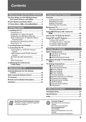
...Removing from P&P and PIP 28 Using TV Settings Media Category Icons 29 Adjusting TV Settings 29 Watching TV 29 Accessing External Inputs 29 Navigating through TV Home Menu on XMB 30 TV...Up the Channel List - Installing the TV 6 Carrying the TV 6 Preparation for Table-Top Stand 6 Preparation for HDMI 25 How to Use TV Guide On Screen 26 Using P&P and...TV Against a Wall or Enclosed Area 8 Bundling the Connecting Cables 8 Securing the TV 9 2. Contents Welcome to the World of optional equipment connection diagrams. Customer Support http://www.sony.com/tvsupport Canada http://www.sony...
...Removing from P&P and PIP 28 Using TV Settings Media Category Icons 29 Adjusting TV Settings 29 Watching TV 29 Accessing External Inputs 29 Navigating through TV Home Menu on XMB 30 TV...Up the Channel List - Installing the TV 6 Carrying the TV 6 Preparation for Table-Top Stand 6 Preparation for HDMI 25 How to Use TV Guide On Screen 26 Using P&P and...TV Against a Wall or Enclosed Area 8 Bundling the Connecting Cables 8 Securing the TV 9 2. Contents Welcome to the World of optional equipment connection diagrams. Customer Support http://www.sony.com/tvsupport Canada http://www.sony...
Operating Instructions
Page 6
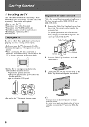
... the assembling steps required to the Table-Top Stand. 6 Installing the TV This TV can be mounted on a wall using a WallMount Bracket or placed on a TV stand (except models: KDL-52V4100 and KDL-52W4100). 1 Remove the Table-Top Stand and screws from the bottom center. ~ • Do not put stress on the LCD panel or the frame around the screen. •...
... the assembling steps required to the Table-Top Stand. 6 Installing the TV This TV can be mounted on a wall using a WallMount Bracket or placed on a TV stand (except models: KDL-52V4100 and KDL-52W4100). 1 Remove the Table-Top Stand and screws from the bottom center. ~ • Do not put stress on the LCD panel or the frame around the screen. •...
Operating Instructions
Page 7
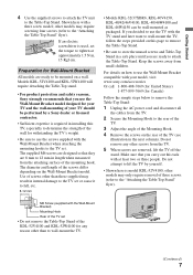
.... Getting Started 4 Use the supplied screws to attach the TV unit to lift the TV by a Sony dealer or licensed contractor. • Sufficient expertise is model KDL-52V4100; Shown here with the TV stand and later want to the rear of the TV. 3 Adjust the angle of the Mounting Hook. 4 Remove the screws on the Wall-Mount Bracket model.
.... Getting Started 4 Use the supplied screws to attach the TV unit to lift the TV by a Sony dealer or licensed contractor. • Sufficient expertise is model KDL-52V4100; Shown here with the TV stand and later want to the rear of the TV. 3 Adjust the angle of the Mounting Hook. 4 Remove the screws on the Wall-Mount Bracket model.
Service Manual
Page 3
... Board Schematic Diagram 78 H4 Board Schematic Diagram 80 3-5. Bezel Assembly and LCD Panel 86 4-5. Screw Legend 87 SECTION 5: ELECTRICAL PARTS LIST 88 APPENDIX A: ENCRYPTION KEY COMPONENTS A-1 KDL-52V4100/52W4100 3 Rear Cover Removal 13 1-2. Viewing Service Adjustment Data 53 2-2. Stand and Under Cover Removal 15 1-6. Resetting to View Service Data ......... 54 2-5. Circuit Boards Location 55 3-2. Switch...
... Board Schematic Diagram 78 H4 Board Schematic Diagram 80 3-5. Bezel Assembly and LCD Panel 86 4-5. Screw Legend 87 SECTION 5: ELECTRICAL PARTS LIST 88 APPENDIX A: ENCRYPTION KEY COMPONENTS A-1 KDL-52V4100/52W4100 3 Rear Cover Removal 13 1-2. Viewing Service Adjustment Data 53 2-2. Stand and Under Cover Removal 15 1-6. Resetting to View Service Data ......... 54 2-5. Circuit Boards Location 55 3-2. Switch...

Service Manual
Page 15
AC INLET REMOVAL 1 Remove 2 screws 2 Remove 1 screw 2 AC Bracket AC Inlet 1 Bottom Bracket KDL-52V4100/52W4100 15 STAND AND UNDER COVER REMOVAL 1 Remove 4 screws 2 Remove 1 screw 1 Under Cover KDL-52V4100/52W4100 Stand Assembly 2 1-6. 1-5.
AC INLET REMOVAL 1 Remove 2 screws 2 Remove 1 screw 2 AC Bracket AC Inlet 1 Bottom Bracket KDL-52V4100/52W4100 15 STAND AND UNDER COVER REMOVAL 1 Remove 4 screws 2 Remove 1 screw 1 Under Cover KDL-52V4100/52W4100 Stand Assembly 2 1-6. 1-5.


