Service Manual
Page 1
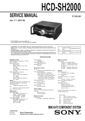
... 500 mA Disc player section System Compact disc and digital audio system Laser Diode Properties Emission Duration: Continuous Laser Output*: Less than 88 dB Tuner section FM stereo, FM/AM superheterodyne tuner Antenna: FM lead antenna AM loop antenna FM tuner section Tuning range 87.5 MHz - 108.0 MHz (50 kHz step) CD CD Mechanism Type CDM86B-DVBU101 Section Optical Pick-up Block with 7 mm aperture. SPECIFICATIONS Amplifi...
... 500 mA Disc player section System Compact disc and digital audio system Laser Diode Properties Emission Duration: Continuous Laser Output*: Less than 88 dB Tuner section FM stereo, FM/AM superheterodyne tuner Antenna: FM lead antenna AM loop antenna FM tuner section Tuning range 87.5 MHz - 108.0 MHz (50 kHz step) CD CD Mechanism Type CDM86B-DVBU101 Section Optical Pick-up Block with 7 mm aperture. SPECIFICATIONS Amplifi...
Service Manual
Page 2
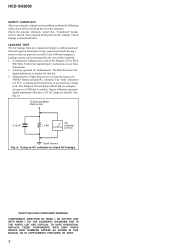
... the antenna terminals, metal trim, "metallized" knobs, screws, and all battery operated digital multimeters that have an accurate low-voltage scale. SAFETY-RELATED COMPONENT WARNING! REPLACE THESE COMPONENTS WITH SONY PARTS WHOSE PART NUMBERS APPEAR AS SHOWN IN THIS MANUAL OR IN SUPPLEMENTS PUBLISHED BY SONY. 2 HCD-SH2000 SAFETY CHECK-OUT After correcting the original service problem, perform the following safety check before releasing the set to check...
... the antenna terminals, metal trim, "metallized" knobs, screws, and all battery operated digital multimeters that have an accurate low-voltage scale. SAFETY-RELATED COMPONENT WARNING! REPLACE THESE COMPONENTS WITH SONY PARTS WHOSE PART NUMBERS APPEAR AS SHOWN IN THIS MANUAL OR IN SUPPLEMENTS PUBLISHED BY SONY. 2 HCD-SH2000 SAFETY CHECK-OUT After correcting the original service problem, perform the following safety check before releasing the set to check...
Service Manual
Page 3
.... SERVICING NOTES 4 2. DMB21 Board 8 2-5. TEST MODE 11 4. Block Diagram - Printed Wiring Board - MAIN Board (Conductor Side) (Suffix 11 21 5-7. DMB21 Board (Conductor Side 33 5-19. DAMP Board (Component Side 37 5-23. Schematic Diagram - DAMP Board (4/4 42 5-28. Printed Wiring Boards - Main Section 65 6-2. CDM Section 69 7. CD MECHANISM DECK BLOCK (1 9 2-7. Schematic Diagram - DISPLAY Board 44 5-30. Schematic Diagram - MIC Board 52 6. Side Panel A, Side Panel B and Top Panel...
.... SERVICING NOTES 4 2. DMB21 Board 8 2-5. TEST MODE 11 4. Block Diagram - Printed Wiring Board - MAIN Board (Conductor Side) (Suffix 11 21 5-7. DMB21 Board (Conductor Side 33 5-19. DAMP Board (Component Side 37 5-23. Schematic Diagram - DAMP Board (4/4 42 5-28. Printed Wiring Boards - Main Section 65 6-2. CDM Section 69 7. CD MECHANISM DECK BLOCK (1 9 2-7. Schematic Diagram - DISPLAY Board 44 5-30. Schematic Diagram - MIC Board 52 6. Side Panel A, Side Panel B and Top Panel...
Service Manual
Page 4
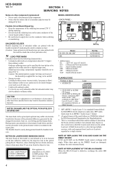
... African model PLAYABLE DISC Format of discs • AUDIO CD Logo • CD-R/-RW in AUDIO CD format • CD-R/-RW in DATA CD format, containing MP3 audio tracks 1) that conforms to ISO 9660 2) Level 1/Level 2, Joliet (in the repair parts. Conventional discs begin at an area called the Lead-in hazardous radiation exposure. HCD-SH2000 Ver. 1.1 SECTION 1 SERVICING NOTES Notes on chip component replacement •...
... African model PLAYABLE DISC Format of discs • AUDIO CD Logo • CD-R/-RW in AUDIO CD format • CD-R/-RW in DATA CD format, containing MP3 audio tracks 1) that conforms to ISO 9660 2) Level 1/Level 2, Joliet (in the repair parts. Conventional discs begin at an area called the Lead-in hazardous radiation exposure. HCD-SH2000 Ver. 1.1 SECTION 1 SERVICING NOTES Notes on chip component replacement •...
Service Manual
Page 11
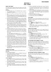
... thus the channel step is changed . The cold reset is used to check the fluorescent indicator tube, LEDs, keys, [MASTER VOLUME] jog, model, destination and software version. COLD RESET The cold reset clears all LEDs light up . Press @/1 button to turn off automatically. 8. Use this mode when returning the set to flat the same time. Press @/1 button to turn on the system. 6. Procedure: 5. Select CD function and without...
... thus the channel step is changed . The cold reset is used to check the fluorescent indicator tube, LEDs, keys, [MASTER VOLUME] jog, model, destination and software version. COLD RESET The cold reset clears all LEDs light up . Press @/1 button to turn off automatically. 8. Use this mode when returning the set to flat the same time. Press @/1 button to turn on the system. 6. Procedure: 5. Select CD function and without...
Service Manual
Page 12
... the factory use to turn on the system. 2. The message "LOCKED" will not eject when [EJECT] button is disc. When this mode is activated, the disc will be ejected. This mode only applied when there is pressed. Originally, frequency of FM 1-FM 20 and AM 1-AM10 are set to be displayed on the system. 2. Select CD function. 3. HCD-SH2000 DISC THEFT PREVENTION MODE This mode let prevent disc to...
... the factory use to turn on the system. 2. The message "LOCKED" will not eject when [EJECT] button is disc. When this mode is activated, the disc will be ejected. This mode only applied when there is pressed. Originally, frequency of FM 1-FM 20 and AM 1-AM10 are set to be displayed on the system. 2. Select CD function. 3. HCD-SH2000 DISC THEFT PREVENTION MODE This mode let prevent disc to...
Service Manual
Page 13
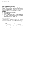
... ohm. 3. You cannot use SG whose output impedance is received in good condition". Carrier frequency : A = 87.5 MHz, B = 98 MHz, C = 108 MHz Deviation : 75 kHz Modulation : 1 kHz ANT input : 35 dBu (EMF) Note: Please use 75 ohm "coaxial cable" to connect SG and the set + 75 - The stop of A, B and C detected and automatic scanning stops. Please use video cable for checking. HCD-SH2000 13 Set to FM antenna input directly. Procedure: 1. Turn the power on. 2. TUNER...
... ohm. 3. You cannot use SG whose output impedance is received in good condition". Carrier frequency : A = 87.5 MHz, B = 98 MHz, C = 108 MHz Deviation : 75 kHz Modulation : 1 kHz ANT input : 35 dBu (EMF) Note: Please use 75 ohm "coaxial cable" to connect SG and the set + 75 - The stop of A, B and C detected and automatic scanning stops. Please use video cable for checking. HCD-SH2000 13 Set to FM antenna input directly. Procedure: 1. Turn the power on. 2. TUNER...
Service Manual
Page 16
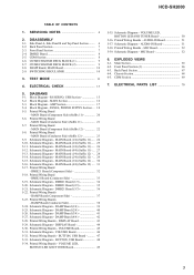
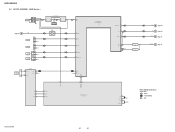
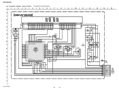
SIGNAL PATH : AUDIO : TUNER (FM/AM) : MIC HCD-SH2000 16 16 HCD-SH2000 5-2. MAIN Section - BLOCK DIAGRAM - J1300 MIC IN A (Page 15) L-OUT J1200 TV R-CH J1201 PC GAME AUDIO IN DVD/SAT AUDIO IN J500 L R L R R-CH R-CH R-CH IC1300 MIC AMP 5 7 3 1 RV1300 MIC LEVEL MIN MAX IC501 OP AMP 5 7 46 MIC 39 GAME_L 43 TV IN-L 45 PC IN-L 40 GAME IN-L 42 DVD/SAT IN-L ANTENNA FM/AM IC1602 TUNER (FM...
SIGNAL PATH : AUDIO : TUNER (FM/AM) : MIC HCD-SH2000 16 16 HCD-SH2000 5-2. MAIN Section - BLOCK DIAGRAM - J1300 MIC IN A (Page 15) L-OUT J1200 TV R-CH J1201 PC GAME AUDIO IN DVD/SAT AUDIO IN J500 L R L R R-CH R-CH R-CH IC1300 MIC AMP 5 7 3 1 RV1300 MIC LEVEL MIN MAX IC501 OP AMP 5 7 46 MIC 39 GAME_L 43 TV IN-L 45 PC IN-L 40 GAME IN-L 42 DVD/SAT IN-L ANTENNA FM/AM IC1602 TUNER (FM...
Service Manual
Page 17
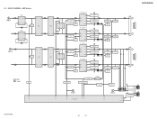
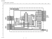
... /FAN-LOCK 61 HCD-SH2000 17 17 D Lch (Page 16) AMPLIFIER IC502 5 INPUT+ OUTPUT 1 7 OUTPUT INPUT+ 3 R-CH AMPLIFIER IC503 5 INPUT+ OUTPUT 1 7 OUTPUT INPUT+ 3 3 INPUT+ OUTPUT 1 MUTE Q601 OP AMP IC805 5 INPUT+ OUTPUT 7 C Lch (Page 16) R-CH 3 INPUT+ OUTPUT 1 MUTE Q600 OP AMP IC600 5 INPUT+ OUTPUT 7 SIGNAL PATH : AUDIO MUTE Q207 51 /LINE-MUTE DAMP-CLK /DAMP-RESET NO USE /SD-SLOW RESONANCE D1403 D1435 HCD-SH2000 LOW SPEAKER IMPEDANCE USE 4ȍ 2 INA- AMP Section - AOUT 1 PREAMP IC1403 5 INB+ BOUT 7 BUFFER IC1410 5 7 3 1 2 INA- BLOCK DIAGRAM -
... /FAN-LOCK 61 HCD-SH2000 17 17 D Lch (Page 16) AMPLIFIER IC502 5 INPUT+ OUTPUT 1 7 OUTPUT INPUT+ 3 R-CH AMPLIFIER IC503 5 INPUT+ OUTPUT 1 7 OUTPUT INPUT+ 3 3 INPUT+ OUTPUT 1 MUTE Q601 OP AMP IC805 5 INPUT+ OUTPUT 7 C Lch (Page 16) R-CH 3 INPUT+ OUTPUT 1 MUTE Q600 OP AMP IC600 5 INPUT+ OUTPUT 7 SIGNAL PATH : AUDIO MUTE Q207 51 /LINE-MUTE DAMP-CLK /DAMP-RESET NO USE /SD-SLOW RESONANCE D1403 D1435 HCD-SH2000 LOW SPEAKER IMPEDANCE USE 4ȍ 2 INA- AMP Section - AOUT 1 PREAMP IC1403 5 INB+ BOUT 7 BUFFER IC1410 5 7 3 1 2 INA- BLOCK DIAGRAM -

Service Manual
Page 18
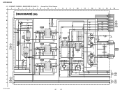
... 21 /FL-DRIVER-CS SYSTEM CONTROLLER IC100 (4/4) 10 - 33 34 - 49 REMOTE CONTROL RECEIVER IC982 MASTER DJ CONTROL S1000 ROTARY ENCODER 4 SIRCS 97 MASTER-VOL D1151 (USB B : BLUE) D1154 (USB B : RED) D1150 (USB A : BLUE) LED DRIVE Q303 LED DRIVE Q301 100 USBB-LED-BLUE MTK-POWER-CTL 43 95 USBB-LED-RED 82 USBA-LED-BLUE D1000 - S1262 S1001 - PANEL, POWER SUPPLY Section...
... 21 /FL-DRIVER-CS SYSTEM CONTROLLER IC100 (4/4) 10 - 33 34 - 49 REMOTE CONTROL RECEIVER IC982 MASTER DJ CONTROL S1000 ROTARY ENCODER 4 SIRCS 97 MASTER-VOL D1151 (USB B : BLUE) D1154 (USB B : RED) D1150 (USB A : BLUE) LED DRIVE Q303 LED DRIVE Q301 100 USBB-LED-BLUE MTK-POWER-CTL 43 95 USBB-LED-RED 82 USBA-LED-BLUE D1000 - S1262 S1001 - PANEL, POWER SUPPLY Section...

Service Manual
Page 19
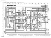
...; Waveforms are taken with a oscilloscope. no -signal (detuned) conditions. F : AUDIO E : USB f : TUNER J : AUDIO (DIGITAL) • Abbreviation E2 : 120 V AC area in E model E51 : Chilean and Peruvian models EA : Saudi Arabia model MX : Mexican model MY : Malaysia model SAF : South African model HCD-SH2000 19 19 HCD-SH2000 Ver. 1.1 Parts face side: Parts on the parts face side seen from (Component Side) the parts face are omitted. t Indication of transistor C Q These...
...; Waveforms are taken with a oscilloscope. no -signal (detuned) conditions. F : AUDIO E : USB f : TUNER J : AUDIO (DIGITAL) • Abbreviation E2 : 120 V AC area in E model E51 : Chilean and Peruvian models EA : Saudi Arabia model MX : Mexican model MY : Malaysia model SAF : South African model HCD-SH2000 19 19 HCD-SH2000 Ver. 1.1 Parts face side: Parts on the parts face side seen from (Component Side) the parts face are omitted. t Indication of transistor C Q These...
Service Manual
Page 26
... 10 16V 10 16V 0.1 0.1 C886 C783 C893 C892 C784 9 R799 4.7k 4.5 4.5 1 OUTPUT VCC 8 2 INPUT- OUTPUT 7 4.5 R853 4.7k 4.5 4.5 3 INPUT+ INPUT- 6 4.5 53 4 GND INPUT+ 5 C780 22p 50V IC805 22p 50V OP-AMP IC805 54 BA4558F R851 47k R852 0 C782 47k R850 C777 10 16V R792 C769 4.7k R793 ... 3P JL401 1 13.5V JL402 2 RED_LED - Q604 LED DRIVER 3.2 C804 1000p 50V C809 23 24 25 MAIN 6 26 BOARD (4/4) 27 (Page 27) 28 29 30 MAIN 7 BOARD 31 (4/4) 32 (Page 27) HCD-SH2000 26 26 SCHEMATIC DIAGRAM - HCD-SH2000 5-11. MAIN BOARD (3/4) (Suffix 11) - &#...
... 10 16V 10 16V 0.1 0.1 C886 C783 C893 C892 C784 9 R799 4.7k 4.5 4.5 1 OUTPUT VCC 8 2 INPUT- OUTPUT 7 4.5 R853 4.7k 4.5 4.5 3 INPUT+ INPUT- 6 4.5 53 4 GND INPUT+ 5 C780 22p 50V IC805 22p 50V OP-AMP IC805 54 BA4558F R851 47k R852 0 C782 47k R850 C777 10 16V R792 C769 4.7k R793 ... 3P JL401 1 13.5V JL402 2 RED_LED - Q604 LED DRIVER 3.2 C804 1000p 50V C809 23 24 25 MAIN 6 26 BOARD (4/4) 27 (Page 27) 28 29 30 MAIN 7 BOARD 31 (4/4) 32 (Page 27) HCD-SH2000 26 26 SCHEMATIC DIAGRAM - HCD-SH2000 5-11. MAIN BOARD (3/4) (Suffix 11) - &#...
Service Manual
Page 30
...replace with single. MAIN board (Suffix-12) that has not been changed appears as TYPE A, and the changed in the midway of production. OUTPUT 7 4.5 R853 4.7k 4.5 4.5 3 INPUT+ INPUT- 6 4.5 53 4 GND INPUT+ 5 C780 22p 50V IC805 22p 50V OP-AMP... RED_LED - SCHEMATIC DIAGRAM - When these parts on the ...AMP IC600 BA4558F 4.5 9 1 OUTPUT VCC 8 4.5 4.5 2 INPUT- JL403 3 BLUE_LED C808 1000p 50V C811 1000p 50V CN704 3P JL404 1 JL405 2 JL406 3 13.5V RED_LED BLUE_LED -&% 41&",&3 3 1000p 50V Q607 RT3TAAM-TP-1 0 0 Q607 - HCD-SH2000 5-15. Q604 LED DRIVER...
...replace with single. MAIN board (Suffix-12) that has not been changed appears as TYPE A, and the changed in the midway of production. OUTPUT 7 4.5 R853 4.7k 4.5 4.5 3 INPUT+ INPUT- 6 4.5 53 4 GND INPUT+ 5 C780 22p 50V IC805 22p 50V OP-AMP... RED_LED - SCHEMATIC DIAGRAM - When these parts on the ...AMP IC600 BA4558F 4.5 9 1 OUTPUT VCC 8 4.5 4.5 2 INPUT- JL403 3 BLUE_LED C808 1000p 50V C811 1000p 50V CN704 3P JL404 1 JL405 2 JL406 3 13.5V RED_LED BLUE_LED -&% 41&",&3 3 1000p 50V Q607 RT3TAAM-TP-1 0 0 Q607 - HCD-SH2000 5-15. Q604 LED DRIVER...
Service Manual
Page 44
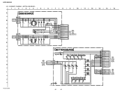
SCHEMATIC DIAGRAM - HCD-SH2000 5-29. DISPLAY BOARD - • See page 54 for IC Block Diagrams. 1 2 3 4 5 6 7 8 9 10 11 12 13 14 15 A B C D E F G H I J DISPLAY BOARD FL901 FLUORESCENT INDICATOR TUBE E+3.3V SIRCS IC982 REMOTE CONTROL SIGNAL RECEIVER IC982 PNA4823M03S0 VCC OUT IR GND 3.4 2.8 JL900 R900 22 C901 0.22 JL901 55 R922 0 JL902 C902 0.1 JL903 JL904 JL905 JL906 JL907 JL909 JL910 JL911 JL913 ...
SCHEMATIC DIAGRAM - HCD-SH2000 5-29. DISPLAY BOARD - • See page 54 for IC Block Diagrams. 1 2 3 4 5 6 7 8 9 10 11 12 13 14 15 A B C D E F G H I J DISPLAY BOARD FL901 FLUORESCENT INDICATOR TUBE E+3.3V SIRCS IC982 REMOTE CONTROL SIGNAL RECEIVER IC982 PNA4823M03S0 VCC OUT IR GND 3.4 2.8 JL900 R900 22 C901 0.22 JL901 55 R922 0 JL902 C902 0.1 JL903 JL904 JL905 JL906 JL907 JL909 JL910 JL911 JL913 ...
Service Manual
Page 46
HCD-SH2000 5-31. SCHEMATIC DIAGRAM - VOLUME BOARD - 1 2 3 4 5 6 7 8 9 10 11 12 13 14 15 A B C D E F G H I J VOLUME BOARD K DISPLAY BOARD CN900 (Page 44) O BUTTON BOARD NO1252 (Page 48) LED+13.5V LED_GND -VG DGND FL_DRIVER_CLK FL_DRIVER_DATA FL_DRIVER_CS +3.3V SIRCS E+3.3V NO1002 11P JL1054 11 JL1055 10 JL1056 9 JL1057 8 JL1062 7 JL1063 6 JL1064 5 JL1075 4 JL1078 3 JL1079 1 AD-KEY-0 STBY-LED DGND MIC DET MIC SIGNAL A+9V MIC GND...
HCD-SH2000 5-31. SCHEMATIC DIAGRAM - VOLUME BOARD - 1 2 3 4 5 6 7 8 9 10 11 12 13 14 15 A B C D E F G H I J VOLUME BOARD K DISPLAY BOARD CN900 (Page 44) O BUTTON BOARD NO1252 (Page 48) LED+13.5V LED_GND -VG DGND FL_DRIVER_CLK FL_DRIVER_DATA FL_DRIVER_CS +3.3V SIRCS E+3.3V NO1002 11P JL1054 11 JL1055 10 JL1056 9 JL1057 8 JL1062 7 JL1063 6 JL1064 5 JL1075 4 JL1078 3 JL1079 1 AD-KEY-0 STBY-LED DGND MIC DET MIC SIGNAL A+9V MIC GND...
Service Manual
Page 48
...-LED-RED 5 USBB-LED-BLUE 6 USB A +5V 7 D-A 8 D+A 9 USB A GND 10 USB B+5V 11 D-B 12 D+B 13 USB B GND MAIN C BOARD (2/4) CN300 (Page 25) (Suffix 11) (Page 29) (Suffix 12) 11 12 13 14 15 F G H I J HCD-SH2000 N BUTTON LED BOARD CN1280 (Page 50) BUTTON BOARD D1251 SLI-325URT31WR R1250 JL1250 1k S1251 S1253 SEARCH S1255 GROOVE S1257 PRESET...
...-LED-RED 5 USBB-LED-BLUE 6 USB A +5V 7 D-A 8 D+A 9 USB A GND 10 USB B+5V 11 D-B 12 D+B 13 USB B GND MAIN C BOARD (2/4) CN300 (Page 25) (Suffix 11) (Page 29) (Suffix 12) 11 12 13 14 15 F G H I J HCD-SH2000 N BUTTON LED BOARD CN1280 (Page 50) BUTTON BOARD D1251 SLI-325URT31WR R1250 JL1250 1k S1251 S1253 SEARCH S1255 GROOVE S1257 PRESET...

Service Manual
Page 61
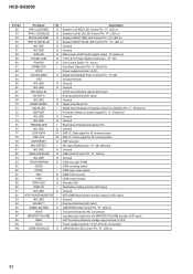
... 44 HUB-RESET O MTK Hub Board reset pin 45 HUB-VBUS-DETECT O Hub Power (V-DET) Control Port 46 FLASH-MEMORY O Update software recovery 47 AUDIO-DATA O Serial data output to audio signal processor, R2A15216FP 48 NO-USE O Unused 49 AUDIO-CLK O Serial data transfer clock signal output to audio signal processor, R2A15216FP 50 NO-USE O Unused 51 /LINE-MUTE O Muting Control Switch for several hundreds msec and then change to...
... 44 HUB-RESET O MTK Hub Board reset pin 45 HUB-VBUS-DETECT O Hub Power (V-DET) Control Port 46 FLASH-MEMORY O Update software recovery 47 AUDIO-DATA O Serial data output to audio signal processor, R2A15216FP 48 NO-USE O Unused 49 AUDIO-CLK O Serial data transfer clock signal output to audio signal processor, R2A15216FP 50 NO-USE O Unused 51 /LINE-MUTE O Muting Control Switch for several hundreds msec and then change to...
Service Manual
Page 62
... pulse input from the MASTER VOLUME encoder (A/D input) A/D Converter reference voltage input terminal (+3.3V) Power supply terminal (+3.3V) (for IIC communcation DSP reset pin Mic Input Detection pin. "H": 13V Fan Control Switch "H": fan on Amplifier Pin. "H": ON Ground terminal Unused Unused VACS level detection signal (A/D input) Key input terminal (A/D input) Unused Digital Amp Reset Pin Digital Amp Shutdown Protection Detect on Fan Block Detection Pin. "H": Mic detected Unused USB A LED Control Pin. HCD-SH2000 Pin...
... pulse input from the MASTER VOLUME encoder (A/D input) A/D Converter reference voltage input terminal (+3.3V) Power supply terminal (+3.3V) (for IIC communcation DSP reset pin Mic Input Detection pin. "H": 13V Fan Control Switch "H": fan on Amplifier Pin. "H": ON Ground terminal Unused Unused VACS level detection signal (A/D input) Key input terminal (A/D input) Unused Digital Amp Reset Pin Digital Amp Shutdown Protection Detect on Fan Block Detection Pin. "H": Mic detected Unused USB A LED Control Pin. HCD-SH2000 Pin...

Service Manual
Page 64
... used O Component video (Pr/Cr) signal output terminal Not used - Not used - Ground terminal O Master clock signal output to the A/D converter and D/A converter O Bit clock signal output to the A/D converter and D/A converter O Muting signal output to the SD-RAM - Ground terminal I AC coupled RF signal input from the optical pick-up block I Power monitor terminal I Spindle motor hall sensor input from the system controller O Communication initialization request acknowledge signal output to the D/A converter - HCD-SH2000...
... used O Component video (Pr/Cr) signal output terminal Not used - Not used - Ground terminal O Master clock signal output to the A/D converter and D/A converter O Bit clock signal output to the A/D converter and D/A converter O Muting signal output to the SD-RAM - Ground terminal I AC coupled RF signal input from the optical pick-up block I Power monitor terminal I Spindle motor hall sensor input from the system controller O Communication initialization request acknowledge signal output to the D/A converter - HCD-SH2000...

Service Manual
Page 70
METAL OXIDE: Metal oxide-film resistor. Some delay should be different from the parts specified in the diagrams or the components used on the set. • -XX and -X mean standardized parts, so they are seldom required for routine service. Part No. Part No. lm BUTTON LED BOARD < CONNECTOR > CN1280 1-564-719-11 PIN, CONNECTOR (SMALL TYPE) 3P < JUMPER RESISTOR...
METAL OXIDE: Metal oxide-film resistor. Some delay should be different from the parts specified in the diagrams or the components used on the set. • -XX and -X mean standardized parts, so they are seldom required for routine service. Part No. Part No. lm BUTTON LED BOARD < CONNECTOR > CN1280 1-564-719-11 PIN, CONNECTOR (SMALL TYPE) 3P < JUMPER RESISTOR...


