Service Manual
Page 11
... and software version. To release from Common Test mode 1. Procedure: 1. Press [CD] button and @/1 button simultaneously. SECTION 3 TEST MODE HCD-SH2000 PANEL TEST MODE This mode is used to its maximum. 2. Press [PRESET EQ] button repeatedly until a message "GEQ FLAT" appears on ...to check operations of 0, 9, 8, 7 ... Press [ x ] button and @/1 button simultaneously for Saudi Arabian, European and Russian models. Select CD function and without dics inserted. 7. A message "MECHA LOCK" is displayed on the fluorescent indicator tube. 5. In the key check mode, the fl...
... and software version. To release from Common Test mode 1. Procedure: 1. Press [CD] button and @/1 button simultaneously. SECTION 3 TEST MODE HCD-SH2000 PANEL TEST MODE This mode is used to its maximum. 2. Press [PRESET EQ] button repeatedly until a message "GEQ FLAT" appears on ...to check operations of 0, 9, 8, 7 ... Press [ x ] button and @/1 button simultaneously for Saudi Arabian, European and Russian models. Select CD function and without dics inserted. 7. A message "MECHA LOCK" is displayed on the fluorescent indicator tube. 5. In the key check mode, the fl...
Service Manual
Page 12
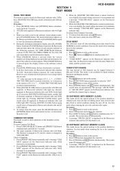
...system. 2. Press @/1 button to load all the factory use preset frequencies into FM 1-FM 20 and AM 1-AM 10. Select CD function. 3. FACTORY PRESET This mode is disc. The message "LOCKED" will not eject when [EJECT] button is changed to turn on the ... 3 seconds, message "FACTORY" appears on the fluorescent indicator tube. Procedure: 1. The function is pressed. Procedure: 1. Press [SEARCH] button and [TUNER/BAND] button simultaneously and hold for 3 seconds. HCD-SH2000 DISC THEFT PREVENTION MODE This mode let prevent disc to the minimum frequency. The message "LOCKED"...
...system. 2. Press @/1 button to load all the factory use preset frequencies into FM 1-FM 20 and AM 1-AM 10. Select CD function. 3. FACTORY PRESET This mode is disc. The message "LOCKED" will not eject when [EJECT] button is changed to turn on the ... 3 seconds, message "FACTORY" appears on the fluorescent indicator tube. Procedure: 1. The function is pressed. Procedure: 1. Press [SEARCH] button and [TUNER/BAND] button simultaneously and hold for 3 seconds. HCD-SH2000 DISC THEFT PREVENTION MODE This mode let prevent disc to the minimum frequency. The message "LOCKED"...
Service Manual
Page 13
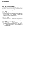
Input the following signal from Signal Generator to FM tuner function and scan the input FM signal with automatic scanning. 4. Please use 75 ohm "coaxial cable" to connect SG and the set + 75 - Set to FM ... : 1 kHz ANT input : 35 dBu (EMF) Note: Please use SG whose output impedance is received in good condition". You cannot use video cable for checking. HCD-SH2000 13 Confirm that input Frequency of automatic scanning means "The station signal is 75 ohm. 3. The stop of A, B and C detected and automatic scanning...
Input the following signal from Signal Generator to FM tuner function and scan the input FM signal with automatic scanning. 4. Please use 75 ohm "coaxial cable" to connect SG and the set + 75 - Set to FM ... : 1 kHz ANT input : 35 dBu (EMF) Note: Please use SG whose output impedance is received in good condition". You cannot use video cable for checking. HCD-SH2000 13 Confirm that input Frequency of automatic scanning means "The station signal is 75 ohm. 3. The stop of A, B and C detected and automatic scanning...
Service Manual
Page 24
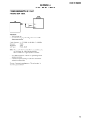
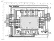
SAF, EA 1k - HCD-SH2000 Ver. 1.1 5-9. MAIN BOARD (1/4) (Suffix 11) - • See page 53 for Waveforms. • See page 61 for IC Pin Function Descriptions. 1 2 3 4 5 6 7 8 9 10 11 12 13 14 15 A MAIN BOARD (1/4) B 80 79 78 77 72 71 70 69 68 C162 C163 100 0.1 16V 63 61 60 ... SWITCHING Q204 RT1N141C-TP-1 0 3.1 0 9 11 10 R258 R259 4.7k 10k 14 13.4 12.7 LED SWITCH Q205 2SB1690TL 13.4 MAIN 3 BOARD (3/4) (Page 26) 12 58 13 HCD-SH2000 24 24 EA 4.7k - E2, E51, MX *2 R290 330 - SCHEMATIC DIAGRAM -
SAF, EA 1k - HCD-SH2000 Ver. 1.1 5-9. MAIN BOARD (1/4) (Suffix 11) - • See page 53 for Waveforms. • See page 61 for IC Pin Function Descriptions. 1 2 3 4 5 6 7 8 9 10 11 12 13 14 15 A MAIN BOARD (1/4) B 80 79 78 77 72 71 70 69 68 C162 C163 100 0.1 16V 63 61 60 ... SWITCHING Q204 RT1N141C-TP-1 0 3.1 0 9 11 10 R258 R259 4.7k 10k 14 13.4 12.7 LED SWITCH Q205 2SB1690TL 13.4 MAIN 3 BOARD (3/4) (Page 26) 12 58 13 HCD-SH2000 24 24 EA 4.7k - E2, E51, MX *2 R290 330 - SCHEMATIC DIAGRAM -

Service Manual
Page 28
... SWITCH Q205 2SB1690TL 13.4 MAIN 3 BOARD (3/4) (Page 30) 12 58 13 HCD-SH2000 28 28 SAF 1k - SCHEMATIC DIAGRAM - SAF, EA 1k - HCD-SH2000 Ver. 1.1 5-13. MAIN BOARD (1/4) (Suffix 12) - • See page 53 for Waveforms. • See page 61 for IC Pin Function Descriptions. 1 2 3 4 5 6 7 8 9 10 11 12 13 14 15 A MAIN BOARD (1/4) B 80...
... SWITCH Q205 2SB1690TL 13.4 MAIN 3 BOARD (3/4) (Page 30) 12 58 13 HCD-SH2000 28 28 SAF 1k - SCHEMATIC DIAGRAM - SAF, EA 1k - HCD-SH2000 Ver. 1.1 5-13. MAIN BOARD (1/4) (Suffix 12) - • See page 53 for Waveforms. • See page 61 for IC Pin Function Descriptions. 1 2 3 4 5 6 7 8 9 10 11 12 13 14 15 A MAIN BOARD (1/4) B 80...

Service Manual
Page 57
... (1/3)) SYSTEM CLOCK SYSTEM CLOCK MANAGER BCK 1 DATA 2 LRCK 3 DGND 4 NC 5 VCC (5V) 6 POWER SUPPLY AUDIO SERIAL PORT SERIAL CONTROL PORT 4x/8x OVERSAMPLING DIGITAL FILTER & FUNCTION CONTROL ENHANCED MULTILEVEL DELTA-SIGMA MODULATOR ZERO DETECT VOUTL 7 VOUTR 8 D/A CONVERTER OUTPUT AMP & LOW-PASS FILTER D/A CONVERTER OUTPUT AMP & LOW-PASS FILTER 16 SCK 15... MODE1 26 MODE0 25 BCKO 24 LRCKO 23 SDOUT 22 VDD 21 DGND 20 TDMI 19 OFMT0 18 OFMT1 17 OWL0 16 OWL1 15 RDY HCD-SH2000 57
... (1/3)) SYSTEM CLOCK SYSTEM CLOCK MANAGER BCK 1 DATA 2 LRCK 3 DGND 4 NC 5 VCC (5V) 6 POWER SUPPLY AUDIO SERIAL PORT SERIAL CONTROL PORT 4x/8x OVERSAMPLING DIGITAL FILTER & FUNCTION CONTROL ENHANCED MULTILEVEL DELTA-SIGMA MODULATOR ZERO DETECT VOUTL 7 VOUTR 8 D/A CONVERTER OUTPUT AMP & LOW-PASS FILTER D/A CONVERTER OUTPUT AMP & LOW-PASS FILTER 16 SCK 15... MODE1 26 MODE0 25 BCKO 24 LRCKO 23 SDOUT 22 VDD 21 DGND 20 TDMI 19 OFMT0 18 OFMT1 17 OWL0 16 OWL1 15 RDY HCD-SH2000 57

Service Manual
Page 61
... pin 43 MTK_POWER_CTRL O Power Control pin for several hundreds msec and then change to "H". 13 XOUT O Main system clock output terminal (8MHz) 14 VSS - HCD-SH2000 • IC Pin Function Descriptions MAIN BOARD (1/4) IC100 R5F3650KBDFA (SYSTEM CONTROL) Pin No. 1 2 3 4 5 6 7 8 9 10 11 12 Pin Name I/O Description FL-DATA O Serial data output signal to FL...
... pin 43 MTK_POWER_CTRL O Power Control pin for several hundreds msec and then change to "H". 13 XOUT O Main system clock output terminal (8MHz) 14 VSS - HCD-SH2000 • IC Pin Function Descriptions MAIN BOARD (1/4) IC100 R5F3650KBDFA (SYSTEM CONTROL) Pin No. 1 2 3 4 5 6 7 8 9 10 11 12 Pin Name I/O Description FL-DATA O Serial data output signal to FL...


