Operating Guide
Page 4
... other hazards. Refer all servicing to rain or water. - Service Damage Requiring Service Unplug the set from the wall outlet and disconnect the antenna or cable system. If the set exhibits a distinct change in damage and will prevent damage to the set due to determine that have fallen into the set...
... other hazards. Refer all servicing to rain or water. - Service Damage Requiring Service Unplug the set from the wall outlet and disconnect the antenna or cable system. If the set exhibits a distinct change in damage and will prevent damage to the set due to determine that have fallen into the set...

Operating Guide
Page 6
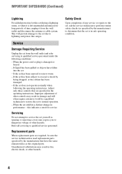
...cable must be determined by the following measures: - Model No. Increase the separation between the equipment and receiver. - Refer to Subpart B of Part 15 of FCC Rules. DCR-HC28 Serial No. Your camcorder is not dustproof, dripproof or waterproof. Viewfinder Battery pack LCD panel • The camcorder... does cause harmful interference to correct the interference by one or more of your Sony dealer regarding this product. Using the camcorder • Do not hold the camcorder by turning the equipment off and on a circuit different from that interference will not...
...cable must be determined by the following measures: - Model No. Increase the separation between the equipment and receiver. - Refer to Subpart B of Part 15 of FCC Rules. DCR-HC28 Serial No. Your camcorder is not dustproof, dripproof or waterproof. Viewfinder Battery pack LCD panel • The camcorder... does cause harmful interference to correct the interference by one or more of your Sony dealer regarding this product. Using the camcorder • Do not hold the camcorder by turning the equipment off and on a circuit different from that interference will not...
Operating Guide
Page 11
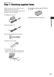
The number in the parentheses indicates the number of the grip belt, as illustrated below, using the strap. 11 Getting Started Getting Started Step 1: Checking supplied items Make sure that item supplied. AC Adaptor (1) (p. 12) Rechargeable battery pack NP-FP30 (1) (p. 12, 66) Operating Guide (This manual) (1) Power cord (1) (p. 12) A/V connecting cable (1) (p. 32, 48) Lens cap (1) (p. 15, 24) • To attach the lens cap Attach the lens cap to the metal fittings of that you have following items supplied with your camcorder.
The number in the parentheses indicates the number of the grip belt, as illustrated below, using the strap. 11 Getting Started Getting Started Step 1: Checking supplied items Make sure that item supplied. AC Adaptor (1) (p. 12) Rechargeable battery pack NP-FP30 (1) (p. 12, 66) Operating Guide (This manual) (1) Power cord (1) (p. 12) A/V connecting cable (1) (p. 32, 48) Lens cap (1) (p. 15, 24) • To attach the lens cap Attach the lens cap to the metal fittings of that you have following items supplied with your camcorder.
Operating Guide
Page 32
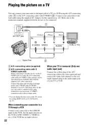
... A/V OUT jack (Yellow) (White) (Red) VCRs or TVs : Signal flow 2 A A/V connecting cable (supplied) B A/V connecting cable with the supplied A/V cable connection. When connecting your camcorder to a TV through a VCR Connect your camcorder to [V-OUT/LCD] (p. 47). Playing the picture on a TV You can connect your camcorder to the audio input jack of your TV or VCR. Set...
... A/V OUT jack (Yellow) (White) (Red) VCRs or TVs : Signal flow 2 A A/V connecting cable (supplied) B A/V connecting cable with the supplied A/V cable connection. When connecting your camcorder to a TV through a VCR Connect your camcorder to [V-OUT/LCD] (p. 47). Playing the picture on a TV You can connect your camcorder to the audio input jack of your TV or VCR. Set...

Operating Guide
Page 48
...TV. • When you connect a device via the S VIDEO jack, by using the A/V connecting cable with an S VIDEO cable, pictures can connect your camcorder to another device via an A/V connecting cable, set [DISP OUT] to a VCR/DVD device, etc., using the supplied AC Adaptor for this...connection is not necessary. You can be reproduced more faithfully than with the supplied A/V cable connection. S VIDEO connection only will not output audio. 48 C i.LINK cable (optional) Use an i.LINK cable to connect your camcorder to [LCD] (the default setting) (p. 47). Dubbing/Editing Dubbing to the ...
...TV. • When you connect a device via the S VIDEO jack, by using the A/V connecting cable with an S VIDEO cable, pictures can connect your camcorder to another device via an A/V connecting cable, set [DISP OUT] to a VCR/DVD device, etc., using the supplied AC Adaptor for this...connection is not necessary. You can be reproduced more faithfully than with the supplied A/V cable connection. S VIDEO connection only will not output audio. 48 C i.LINK cable (optional) Use an i.LINK cable to connect your camcorder to [LCD] (the default setting) (p. 47). Dubbing/Editing Dubbing to the ...
Operating Guide
Page 49
... output via the DV Interface (i.LINK): - When dubbing to a VCR. • When connected using an i.LINK cable, the recorded picture becomes rough when a picture is complete, stop your camcorder and the VCR/DVD device. • To record the date/time and camera settings data when connected by the ...A/V connecting cable, display them on the screen (p. 39, 47). • The following cannot be displayed or ...
... output via the DV Interface (i.LINK): - When dubbing to a VCR. • When connected using an i.LINK cable, the recorded picture becomes rough when a picture is complete, stop your camcorder and the VCR/DVD device. • To record the date/time and camera settings data when connected by the ...A/V connecting cable, display them on the screen (p. 39, 47). • The following cannot be displayed or ...

Operating Guide
Page 50
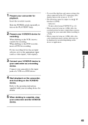
...the instruction manuals supplied with an i.LINK cable. • The indicator appears when you connect your camcorder and other devices via an i.LINK cable. (This indicator may also appear on the PLAY/ EDIT lamp. 50 4 Set your camcorder to the wall outlet using the i.LINK cable (optional). Touch t [PAGE3] t [...TV, VCR/DVD or an i.LINK-compatible device using the supplied AC Adaptor for recording in your camcorder to insert a cassette for this operation (p. 12). Using an i.LINK cable (optional), you are recording from a VCR/DVD device: Start playing the cassette or the disc ...
...the instruction manuals supplied with an i.LINK cable. • The indicator appears when you connect your camcorder and other devices via an i.LINK cable. (This indicator may also appear on the PLAY/ EDIT lamp. 50 4 Set your camcorder to the wall outlet using the i.LINK cable (optional). Touch t [PAGE3] t [...TV, VCR/DVD or an i.LINK-compatible device using the supplied AC Adaptor for recording in your camcorder to insert a cassette for this operation (p. 12). Using an i.LINK cable (optional), you are recording from a VCR/DVD device: Start playing the cassette or the disc ...

Operating Guide
Page 51
... recorded in 4CH MIC mode. - When the write-protect tab of the tape. - On sections recorded in a TV color system other than that of your camcorder is set to start recording. 7 Stop recording. Dubbing sound to a recorded tape You can record audio by using the internal stereo microphone. • You cannot... record additional audio: - Check the picture on the LCD screen or the viewfinder. On blank sections of the cassette is connected via an i.LINK cable. - When your camcorder (p. 64). -
... recorded in 4CH MIC mode. - When the write-protect tab of the tape. - On sections recorded in a TV color system other than that of your camcorder is set to start recording. 7 Stop recording. Dubbing sound to a recorded tape You can record audio by using the internal stereo microphone. • You cannot... record additional audio: - Check the picture on the LCD screen or the viewfinder. On blank sections of the cassette is connected via an i.LINK cable. - When your camcorder (p. 64). -
Operating Guide
Page 58
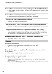
... high. This is not correctly displayed. • Deactivate the NightShot plus function (p. 26), or cancel the BACK LIGHT function (p. 26). The color of the A/V connecting cable are not clear or do not appear. • Clean the head using an S VIDEO plug, make sure the red and white plugs of the picture...
... high. This is not correctly displayed. • Deactivate the NightShot plus function (p. 26), or cancel the BACK LIGHT function (p. 26). The color of the A/V connecting cable are not clear or do not appear. • Clean the head using an S VIDEO plug, make sure the red and white plugs of the picture...

Operating Guide
Page 60
...sound) side until the sound is not connected properly. You cannot dub correctly using the A/V connecting cable. • The A/V connecting cable is heard appropriately (p. 52). You cannot view the video your camcorder is connected to the input jack of the connected device. • Set [DISP OUT] to... a computer The computer does not recognize your camcorder (p. 48). Make sure that the A/V connecting cable is seeing on the camcorder, then connect it again. 60 Pictures from the computer, then connect it again. Connecting to [LCD]...
...sound) side until the sound is not connected properly. You cannot dub correctly using the A/V connecting cable. • The A/V connecting cable is heard appropriately (p. 52). You cannot view the video your camcorder is connected to the input jack of the connected device. • Set [DISP OUT] to... a computer The computer does not recognize your camcorder (p. 48). Make sure that the A/V connecting cable is seeing on the camcorder, then connect it again. 60 Pictures from the computer, then connect it again. Connecting to [LCD]...

Operating Guide
Page 62
...low. • Change the battery (p. 12, 66). QZ The tape is locked - Use a cleaning cassette. (p. 69) Cannot start Easy Handycam. (p. 22, 54) Cannot cancel Easy Handycam. (p. 22, 54) 62 Eject the cassette (p. 69) % Moisture condensation. Cannot add audio. (p. 51) Not recorded in SP mode. ...Disconnect the i.LINK cable. (p. 51) Not recorded in 12-bit audio. Use a new one. (p. 66) Z Re-attach the power source. (p. 12) Use new ...
...low. • Change the battery (p. 12, 66). QZ The tape is locked - Use a cleaning cassette. (p. 69) Cannot start Easy Handycam. (p. 22, 54) Cannot cancel Easy Handycam. (p. 22, 54) 62 Eject the cassette (p. 69) % Moisture condensation. Cannot add audio. (p. 51) Not recorded in SP mode. ...Disconnect the i.LINK cable. (p. 51) Not recorded in 12-bit audio. Use a new one. (p. 66) Z Re-attach the power source. (p. 12) Use new ...

Operating Guide
Page 66
... • When charging the battery pack while the AC Adaptor is connected to your camcorder, after charging is complete, disconnect the cable from your camcorder and put it in an ambient temperature of between your camcorder, and displays the remaining battery time in recording standby or playback pause. • Have...this temperature range, you can use it up , and insert it in a dry, cool place. • To discharge the battery pack on your camcorder right before you start using a large capacity battery pack: NP-FP71/FP90/FH70/FH100 (optional). • Be sure to set [A.SHUT OFF] ...
... • When charging the battery pack while the AC Adaptor is connected to your camcorder, after charging is complete, disconnect the cable from your camcorder and put it in an ambient temperature of between your camcorder, and displays the remaining battery time in recording standby or playback pause. • Have...this temperature range, you can use it up , and insert it in a dry, cool place. • To discharge the battery pack on your camcorder right before you start using a large capacity battery pack: NP-FP71/FP90/FH70/FH100 (optional). • Be sure to set [A.SHUT OFF] ...
Operating Guide
Page 67
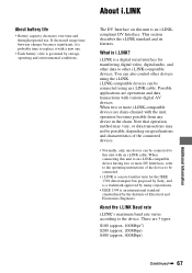
... 200Mbps) S400 (approx. 400Mbps) Additional Information Continued , 67 If decreased usage time between charges becomes significant, it with an i.LINK cable. The DV Interface on specifications and characteristics of Electrical and Electronics Engineers. i.LINK is a digital serial interface for the IEEE 1394 data ...transport bus proposed by Sony, and is a trademark approved by many corporations. • IEEE 1394 is probably time to other i.LINK-compatible devices. ...
... 200Mbps) S400 (approx. 400Mbps) Additional Information Continued , 67 If decreased usage time between charges becomes significant, it with an i.LINK cable. The DV Interface on specifications and characteristics of Electrical and Electronics Engineers. i.LINK is a digital serial interface for the IEEE 1394 data ...transport bus proposed by Sony, and is a trademark approved by many corporations. • IEEE 1394 is probably time to other i.LINK-compatible devices. ...

Operating Guide
Page 68
... - Noise may not be sent in one second. If sand or dust gets in one second. If your camcorder and have it checked by a Sony dealer before connecting (or disconnecting) an i.LINK cable. Doing so might cause heat to record properly. - Mbps stands for the device to other i.LINK (DV ...or anywhere dusty. This damages the inside the casing, unplug your camcorder gets wet, it . • Keep metal contacts clean. To use i.LINK functions on this unit For details on the product. About the required i.LINK cable Use the Sony i.LINK 4-pin-to a device with DV devices. Near AM receivers...
... - Noise may not be sent in one second. If sand or dust gets in one second. If your camcorder and have it checked by a Sony dealer before connecting (or disconnecting) an i.LINK cable. Doing so might cause heat to record properly. - Mbps stands for the device to other i.LINK (DV ...or anywhere dusty. This damages the inside the casing, unplug your camcorder gets wet, it . • Keep metal contacts clean. To use i.LINK functions on this unit For details on the product. About the required i.LINK cable Use the Sony i.LINK 4-pin-to a device with DV devices. Near AM receivers...

Operating Guide
Page 70
...using the supplied AC Adaptor during the operation. 1 Slide the POWER switch to OFF(CHG). 2 Eject the cassette from your camcorder, then disconnect any connecting cables except the AC Adaptor from step 4 again. • You cannot calibrate the LCD screen if it in contact with the ...Continued) • The video heads will wear after using your Sony dealer or local authorized Sony service facility to have the video heads replaced. If you operate your hands. - Using chemicals such as described above substances on your camcorder about 5 seconds. 4 Touch the "×" displayed on ...
...using the supplied AC Adaptor during the operation. 1 Slide the POWER switch to OFF(CHG). 2 Eject the cassette from your camcorder, then disconnect any connecting cables except the AC Adaptor from step 4 again. • You cannot calibrate the LCD screen if it in contact with the ...Continued) • The video heads will wear after using your Sony dealer or local authorized Sony service facility to have the video heads replaced. If you operate your hands. - Using chemicals such as described above substances on your camcorder about 5 seconds. 4 Touch the "×" displayed on ...

Operating Guide
Page 74
...MIX 52 AUDIO MODE 46 AUTO SHTR (Auto shutter 43 A.SHUT OFF (Auto shut off 47 A/V connecting cable .....32, 48 A/V OUT jack 32, 48 B BACK LIGHT 26, 57 BATT (battery) release lever...Double speed Playback........ 40 Dubbing 48, 51 DV Interface 48, 50, 53 E EASY button 22 Easy Handycam 22, 35 EDITSEARCH 30, 44 END SCH (END SEARCH 30, 57 EXPOSURE 38, 59 F FADER...57 Frame-by-frame Playback ....40 Full charge 13 G Getting started 11 Grip belt 15 H Holding the camcorder .........15 I Icon....... See Display indicators ID-1/ID-2 44 Indicators 29 INDOOR 38 "InfoLITHIUM" battery pack 66 ...
...MIX 52 AUDIO MODE 46 AUTO SHTR (Auto shutter 43 A.SHUT OFF (Auto shut off 47 A/V connecting cable .....32, 48 A/V OUT jack 32, 48 B BACK LIGHT 26, 57 BATT (battery) release lever...Double speed Playback........ 40 Dubbing 48, 51 DV Interface 48, 50, 53 E EASY button 22 Easy Handycam 22, 35 EDITSEARCH 30, 44 END SCH (END SEARCH 30, 57 EXPOSURE 38, 59 F FADER...57 Frame-by-frame Playback ....40 Full charge 13 G Getting started 11 Grip belt 15 H Holding the camcorder .........15 I Icon....... See Display indicators ID-1/ID-2 44 Indicators 29 INDOOR 38 "InfoLITHIUM" battery pack 66 ...

Operating Guide
Page 75
... button 22, 24 Rechargeable battery pack See Battery Recording 24 Recording capacity 28 Recording time 13 REMAIN 46 RESET button 27 Reversal Playback 40 S S VIDEO cable 32, 48 S VIDEO jack 32, 48 Searching for the starting point 30 Self-diagnosis display...........61 SEPIA 43 Setting the date and time ......19 SETUP...
... button 22, 24 Rechargeable battery pack See Battery Recording 24 Recording capacity 28 Recording time 13 REMAIN 46 RESET button 27 Reversal Playback 40 S S VIDEO cable 32, 48 S VIDEO jack 32, 48 Searching for the starting point 30 Self-diagnosis display...........61 SEPIA 43 Setting the date and time ......19 SETUP...


