Operating Instructions
Page 9
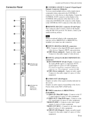
... piece of video equipment. For details, contact your authorized Sony dealers. AUDIO (Stereo minijack) : Inputs an audio signal. VIDEO IN (BNC) : Connects to the video signal output of a piece of video equipment. Connect the CONTROL S OUT connector on this display to the .... IN CONTROL S OUT REMOTE Connector Panel 1 2 3 4 5 DVI-HDCP INPUT 1 AUDIO RGB/COMPONENT INPUT 2 AUDIO L AUDIO OUT R S VIDEO IN OUT VIDEO IN 6 7 OPTION1 Slot (VIDEO/COM ) VIDEO INPUT ADAPTOR OUT AUDIO IN L R 8 OPTION2 Slot (VIDEO) (Only for the FWD-40LX1) Location and Function of Parts and...
... piece of video equipment. For details, contact your authorized Sony dealers. AUDIO (Stereo minijack) : Inputs an audio signal. VIDEO IN (BNC) : Connects to the video signal output of a piece of video equipment. Connect the CONTROL S OUT connector on this display to the .... IN CONTROL S OUT REMOTE Connector Panel 1 2 3 4 5 DVI-HDCP INPUT 1 AUDIO RGB/COMPONENT INPUT 2 AUDIO L AUDIO OUT R S VIDEO IN OUT VIDEO IN 6 7 OPTION1 Slot (VIDEO/COM ) VIDEO INPUT ADAPTOR OUT AUDIO IN L R 8 OPTION2 Slot (VIDEO) (Only for the FWD-40LX1) Location and Function of Parts and...
Operating Instructions
Page 10
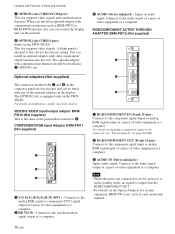
...install an optional adaptor with video signal input/ output function into... a piece of video equipment or a computer. A blank panel is not connected ...display. You can control the display unit via the network. 8 OPTION2 slot (VIDEO port) (Only for system expansion, BKM-FW series, refer to an AC power or is equipped only on the Option Adaptors for the FWD-40LX1) This slot supports video...or component (YUV) signal output of a piece of video equipment or a computer. 2 HD VD IN : ...(VIDEO/COM port) This slot supports video signals and communication function. Location and Function of video...
...install an optional adaptor with video signal input/ output function into... a piece of video equipment or a computer. A blank panel is not connected ...display. You can control the display unit via the network. 8 OPTION2 slot (VIDEO port) (Only for system expansion, BKM-FW series, refer to an AC power or is equipped only on the Option Adaptors for the FWD-40LX1) This slot supports video...or component (YUV) signal output of a piece of video equipment or a computer. 2 HD VD IN : ...(VIDEO/COM port) This slot supports video signals and communication function. Location and Function of video...
Operating Instructions
Page 17
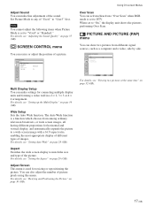
... Screen This menu is set to "Vivid" or "Standard." Note You cannot adjust the following items when Picture Mode is used for connecting multiple display units and forming a video wall in a 2 × 2, 3 × 3 or 4 × 4 arrangement. For details, see "Viewing two pictures at the same time" on page 29 (GB). Aspect Switches...
... Screen This menu is set to "Vivid" or "Standard." Note You cannot adjust the following items when Picture Mode is used for connecting multiple display units and forming a video wall in a 2 × 2, 3 × 3 or 4 × 4 arrangement. For details, see "Viewing two pictures at the same time" on page 29 (GB). Aspect Switches...
Operating Instructions
Page 18
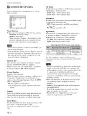
.../V Sync Sync On Green Video signal Synchronizing signal See "Pin assignment" on page 44 (GB) for which only synchronizing signals can enjoy viewing pictures while reducing power consumption. DTV: When connected to a PC. Signals can display closed captions. Color Matrix Sets the Color Matrix to show pictures ... Select Set ENTER Exit MENU Power Saving Reduces power consumption while showing pictures. In this case, an image will not be displayed even if a video signal is reduced so that you may lose the energy saving effects if you try to the signal input at pin 13 of...
.../V Sync Sync On Green Video signal Synchronizing signal See "Pin assignment" on page 44 (GB) for which only synchronizing signals can enjoy viewing pictures while reducing power consumption. DTV: When connected to a PC. Signals can display closed captions. Color Matrix Sets the Color Matrix to show pictures ... Select Set ENTER Exit MENU Power Saving Reduces power consumption while showing pictures. In this case, an image will not be displayed even if a video signal is reduced so that you may lose the energy saving effects if you try to the signal input at pin 13 of...
Operating Instructions
Page 19
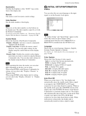
... 19 (GB) Illumination Switches the brightness of the "SONY" logo on the front of the Remote Commander. Control Mode Selects the function of the display unit. You can only make settings for more than about five minutes. Display + Remote: Activates a remote commander supplied with the Remote... be set the Security Lock option. Index Number Sets the index number of video signals. Remote Only: Disables the controls on the display unit when you can select the on the display unit for setting, you set the Color System automatically. When using ENTER on...
... 19 (GB) Illumination Switches the brightness of the "SONY" logo on the front of the Remote Commander. Control Mode Selects the function of the display unit. You can only make settings for more than about five minutes. Display + Remote: Activates a remote commander supplied with the Remote... be set the Security Lock option. Index Number Sets the index number of video signals. Remote Only: Disables the controls on the display unit when you can select the on the display unit for setting, you set the Color System automatically. When using ENTER on...
Operating Instructions
Page 21
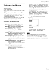
...connectors of the option 1 or 2 slot. Watching the Picture Before you start • Power on the display. • Power on the connected equipment and play a video source. • To display the input signal information and Picture Mode on the screen when turning on the power or switching the input signal..., set "Display" in the Custom Setup menu to disturbance of the sync signal. 21 (GB) The selected...
...connectors of the option 1 or 2 slot. Watching the Picture Before you start • Power on the display. • Power on the connected equipment and play a video source. • To display the input signal information and Picture Mode on the screen when turning on the power or switching the input signal..., set "Display" in the Custom Setup menu to disturbance of the sync signal. 21 (GB) The selected...

Operating Instructions
Page 23
... set to composite video. Option 1/2 Video The signal mode of Apple Computer, Inc. Notes • When inputting an HDTV signal, input the tri-level sync signal to the 2nd pin of RGB/COMPONENT (D-sub 15 pin) on -screen display of the unit's status On-screen display Significance 640×... the Picture a) VGA is no input signal. c) Mac (Macintosh) is component video. Actual on the INPUT2 connector or the BKM-FW12. • If colors appear too light after inputting a DVD signal to the display unit, adjust the "Chroma" setting in the Adjust Picture menu. • When...
... set to composite video. Option 1/2 Video The signal mode of Apple Computer, Inc. Notes • When inputting an HDTV signal, input the tri-level sync signal to the 2nd pin of RGB/COMPONENT (D-sub 15 pin) on -screen display of the unit's status On-screen display Significance 640×... the Picture a) VGA is no input signal. c) Mac (Macintosh) is component video. Actual on the INPUT2 connector or the BKM-FW12. • If colors appear too light after inputting a DVD signal to the display unit, adjust the "Chroma" setting in the Adjust Picture menu. • When...
Operating Instructions
Page 28
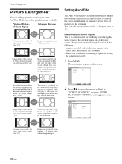
... being enlarged. Images are enlarged to suite your taste. How ya doing ? Full Images from a video camera or DVD software with aspect ratio information (ID-1 type) Images are displayed while enlarging to 16:9. Identification Control Signal This is displayed on a television screen. Original Picture (Picture Type) Enlarged Picture Wide Zoom Ordinary pictures with...
... being enlarged. Images are enlarged to suite your taste. How ya doing ? Full Images from a video camera or DVD software with aspect ratio information (ID-1 type) Images are displayed while enlarging to 16:9. Identification Control Signal This is displayed on a television screen. Original Picture (Picture Type) Enlarged Picture Wide Zoom Ordinary pictures with...
Operating Instructions
Page 32
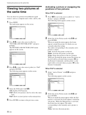
... the cursor (yellow) to "PICTURE AND PICTURE (PAP)" and press ENTER. When you can show two pictures from different signal sources, such as a computer and a video, side by side at the same time You can currently adjust the setting. PICTURE AND PICTURE(PAP) PAP: Active Picture: Picture Size: Picture Position P&P Left...
... the cursor (yellow) to "PICTURE AND PICTURE (PAP)" and press ENTER. When you can show two pictures from different signal sources, such as a computer and a video, side by side at the same time You can currently adjust the setting. PICTURE AND PICTURE(PAP) PAP: Active Picture: Picture Size: Picture Position P&P Left...
Operating Instructions
Page 33
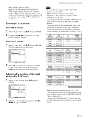
While not showing the menu screen, the main picture will be activated when you press < on the Remote Commander, and the inset picture will be activated when you press , on a picture When P&P is selected 1 Select "Picture Size" with M/m and press ENTER. 2 Keep pressing Zooming in on the Remote Commander. Swap: Swaps the main and the inset pictures. Sub: Activates the inset picture.
While not showing the menu screen, the main picture will be activated when you press < on the Remote Commander, and the inset picture will be activated when you press , on a picture When P&P is selected 1 Select "Picture Size" with M/m and press ENTER. 2 Keep pressing Zooming in on the Remote Commander. Swap: Swaps the main and the inset pictures. Sub: Activates the inset picture.
Operating Instructions
Page 34
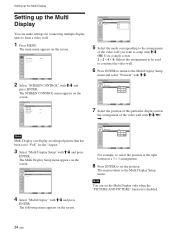
... you want to setup with M/m. Setting up the Multi Display Setting up the Multi Display You can display an enlarged picture that has been set to "Full" for connecting multiple display units to form a video wall. 1 Press MENU. SCREEN CONTROL Multi Display Setup Wide Setup Wide Mode: Full Adjust Screen Over Scan: On Select Set ENTER...
... you want to setup with M/m. Setting up the Multi Display Setting up the Multi Display You can display an enlarged picture that has been set to "Full" for connecting multiple display units to form a video wall. 1 Press MENU. SCREEN CONTROL Multi Display Setup Wide Setup Wide Mode: Full Adjust Screen Over Scan: On Select Set ENTER...
Operating Instructions
Page 43
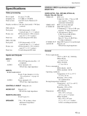
... Active Matrix LCD Panel Display resolution 1366 dots (horizontal) × 768 lines (vertical) FWD-40LX1: Pixel pitch 0.648 (horizontal) × 0.648 (vertical) mm (1⁄32 × 1⁄32 inches) Picture size 885 (horizontal) × 498 (vertical) mm (34 7⁄8 × 19 5⁄8 inches) Panel size 40-inch (diagonal 1016 mm) FWD-32LX1R: Pixel pitch Picture size Panel size 0.510...
... Active Matrix LCD Panel Display resolution 1366 dots (horizontal) × 768 lines (vertical) FWD-40LX1: Pixel pitch 0.648 (horizontal) × 0.648 (vertical) mm (1⁄32 × 1⁄32 inches) Picture size 885 (horizontal) × 498 (vertical) mm (34 7⁄8 × 19 5⁄8 inches) Panel size 40-inch (diagonal 1016 mm) FWD-32LX1R: Pixel pitch Picture size Panel size 0.510...
Operating Instructions
Page 44
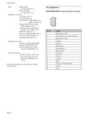
...215;3) (1) BNC-RCA adaptor (1) Remote Commander RM-980 (1) Size AAA (R03) batteries (2) Operating instructions (1) Optional accessories Display stand SU-42FW/32FW Speaker SS-SP40FW/32FW Option Adaptors for system expansion, BKM-FW series Safety regulations UL1950, CSA No...ground Not used Ground Ground SDA H sync or Composite Video V sync SCL 44 (GB) Specifications Mass FWD-40LX1: 27.5 kg (60 lb 10 oz) FWD-32LX1R: 17.5 kg (38 lb 9 oz) Supplied accessories AC power cord (1) AC plug holder (2) Cable holder FWD-40LX1: (4) FWD-32LX1R: (6) Digital RGB (DVI-D) Signal Cable (Single ...
...215;3) (1) BNC-RCA adaptor (1) Remote Commander RM-980 (1) Size AAA (R03) batteries (2) Operating instructions (1) Optional accessories Display stand SU-42FW/32FW Speaker SS-SP40FW/32FW Option Adaptors for system expansion, BKM-FW series Safety regulations UL1950, CSA No...ground Not used Ground Ground SDA H sync or Composite Video V sync SCL 44 (GB) Specifications Mass FWD-40LX1: 27.5 kg (60 lb 10 oz) FWD-32LX1R: 17.5 kg (38 lb 9 oz) Supplied accessories AC power cord (1) AC plug holder (2) Cable holder FWD-40LX1: (4) FWD-32LX1R: (6) Digital RGB (DVI-D) Signal Cable (Single ...


