
Instruction Manual
Page 3
...the manufacturer, as a bookcase, or built-in the cabinet are not sure of the type of the set from battery power, or other similar surface. - Never cover the slots and openings with water for future reference. Do not defeat the safety purpose of power source indicated on an...the cord exits from overheating, these safety instructions completely before cleaning or polishing it is not likely to the set may be blocked or covered. - To ensure reliable operation of any kind into the power outlet only one blade wider than the other materials. - IMPORTANT SAFEGUARDS ...
...the manufacturer, as a bookcase, or built-in the cabinet are not sure of the type of the set from battery power, or other similar surface. - Never cover the slots and openings with water for future reference. Do not defeat the safety purpose of power source indicated on an...the cord exits from overheating, these safety instructions completely before cleaning or polishing it is not likely to the set may be blocked or covered. - To ensure reliable operation of any kind into the power outlet only one blade wider than the other materials. - IMPORTANT SAFEGUARDS ...
Instruction Manual
Page 9
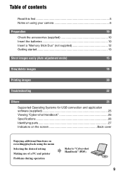
...camera 6 Preparation 10 Check the accessories (supplied 10 Insert the batteries 10 Insert a "Memory Stick Duo" (not supplied 12 Getting started 13 Shoot images easily (Auto adjustment mode) 15 View/delete images 18 Printing images 20 Troubleshooting 22 Others 25 Supported Operating Systems for USB connection and application software (supplied 25 Viewing "Cyber-shot... Handbook 25 Specifications 26 Identifying parts 27 Indicators on the screen Back cover Enjoying additional functions on recording/playback using ...
...camera 6 Preparation 10 Check the accessories (supplied 10 Insert the batteries 10 Insert a "Memory Stick Duo" (not supplied 12 Getting started 13 Shoot images easily (Auto adjustment mode) 15 View/delete images 18 Printing images 20 Troubleshooting 22 Others 25 Supported Operating Systems for USB connection and application software (supplied 25 Viewing "Cyber-shot... Handbook 25 Specifications 26 Identifying parts 27 Indicators on the screen Back cover Enjoying additional functions on recording/playback using ...
Instruction Manual
Page 10
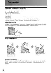
... damage by being dropped, etc. Close the battery/ "Memory Stick Duo" cover. Preparation Check the accessories (supplied) Accessories (supplied) list • LR6 (size AA) alkaline batteries (2) • A/V cable (1) • USB cable (1) • Wrist strap (1) • CD-ROM (Cyber-shot application software, handbook "Cyber-shot Handbook") (1) • Operating instructions for digital still camera "Instruction Manual" (this manual) (1) Attach the wrist...
... damage by being dropped, etc. Close the battery/ "Memory Stick Duo" cover. Preparation Check the accessories (supplied) Accessories (supplied) list • LR6 (size AA) alkaline batteries (2) • A/V cable (1) • USB cable (1) • Wrist strap (1) • CD-ROM (Cyber-shot application software, handbook "Cyber-shot Handbook") (1) • Operating instructions for digital still camera "Instruction Manual" (this manual) (1) Attach the wrist...

Instruction Manual
Page 12
...turn off the power as data may vary, depending on the battery manufacturer/type, environmental conditions, product setting, etc. • The alkaline battery (supplied) is for trial use . To remove a "Memory Stick Duo" Open the battery/"Memory Stick Duo" cover, then push the "Memory Stick Duo" in until it clicks....Duo" can be recorded on the various capacities of still images and approximate movie recording time that can be corrupted. Access lamp The camera has approx. 25 MB of still images (Image quality is recommended. The table below shows the approximate total number of "Memory ...
...turn off the power as data may vary, depending on the battery manufacturer/type, environmental conditions, product setting, etc. • The alkaline battery (supplied) is for trial use . To remove a "Memory Stick Duo" Open the battery/"Memory Stick Duo" cover, then push the "Memory Stick Duo" in until it clicks....Duo" can be recorded on the various capacities of still images and approximate movie recording time that can be corrupted. Access lamp The camera has approx. 25 MB of still images (Image quality is recommended. The table below shows the approximate total number of "Memory ...

Instruction Manual
Page 13
... (Setup) setting, then press B again. 3 Select (Setup2) with V, then press B. 2 4 Select [Clock Set] with V, then press B. 5 Select [OK] with the power off as the cover opens and the lens portion extends. The POWER lamp goes out. • When turning on the power, do not touch the lens portion as this... may cause a malfunction. • If the camera is running on battery power and you do not leave the camera with the lens portion extended for a long period of time with v, then press z. 13 Also, do not operate the...
... (Setup) setting, then press B again. 3 Select (Setup2) with V, then press B. 2 4 Select [Clock Set] with V, then press B. 5 Select [OK] with the power off as the cover opens and the lens portion extends. The POWER lamp goes out. • When turning on the power, do not touch the lens portion as this... may cause a malfunction. • If the camera is running on battery power and you do not leave the camera with the lens portion extended for a long period of time with v, then press z. 13 Also, do not operate the...
Instruction Manual
Page 22
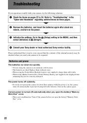
...Sony dealer or local authorized Sony service facility. The power turns off the camera before you do not operate the camera for about one minute, and turn on the power. 3 Initialize the settings. Camera power is on the camera again. Replace them sufficiently. • When using the camera in the "Cyber-shot... Handbook" regarding unlisted items on these pages. 2 Remove the batteries, and insert the batteries again after about three minutes while the power is turned off automatically to be checked when you open the battery/"Memory Stick Duo" cover. 22...
...Sony dealer or local authorized Sony service facility. The power turns off the camera before you do not operate the camera for about one minute, and turn on the power. 3 Initialize the settings. Camera power is on the camera again. Replace them sufficiently. • When using the camera in the "Cyber-shot... Handbook" regarding unlisted items on these pages. 2 Remove the batteries, and insert the batteries again after about three minutes while the power is turned off automatically to be checked when you open the battery/"Memory Stick Duo" cover. 22...
Instruction Manual
Page 27
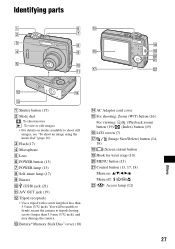
...edit images • For details on : v/V/b/B/z Menu off: / / / V Access lamp (12) 27 You will be unable to firmly secure the camera to shoot still images, see "To shoot an image using the mode dial" (page 16). C Flash (17) D Microphone E Lens F POWER button ... (19) L Tripod receptacle • Use a tripod with a screw length of less than 5.5 mm (7/32 inch), and may damage the camera. wa 5 q; M Battery/"Memory Stick Duo" cover (10) N AC Adaptor cord cover O For shooting: Zoom (W/T) button (16) For viewing: / (Playback zoom) button (19)/ (Index) button (19) P LCD screen ...
...edit images • For details on : v/V/b/B/z Menu off: / / / V Access lamp (12) 27 You will be unable to firmly secure the camera to shoot still images, see "To shoot an image using the mode dial" (page 16). C Flash (17) D Microphone E Lens F POWER button ... (19) L Tripod receptacle • Use a tripod with a screw length of less than 5.5 mm (7/32 inch), and may damage the camera. wa 5 q; M Battery/"Memory Stick Duo" cover (10) N AC Adaptor cord cover O For shooting: Zoom (W/T) button (16) For viewing: / (Playback zoom) button (19)/ (Index) button (19) P LCD screen ...

Service Manual
Page 6
... a slot. 3 Pull the battery case in the direction of arrow A. 1 1 2 1 2 4 3 1 Mode dial Take it off pulling over to upward. The following flow chart shows the disassembly procedure. 2-1. DISASSEMBLY 2. Push down adjusting rib width when attaching. 2 Shutter button 3 Shutter button spring DSC-S500 3 1 Two tapping screws (M1.7x3.5) silver 2 Middle cover assembly (right) 3 Tapping screw...
... a slot. 3 Pull the battery case in the direction of arrow A. 1 1 2 1 2 4 3 1 Mode dial Take it off pulling over to upward. The following flow chart shows the disassembly procedure. 2-1. DISASSEMBLY 2. Push down adjusting rib width when attaching. 2 Shutter button 3 Shutter button spring DSC-S500 3 1 Two tapping screws (M1.7x3.5) silver 2 Middle cover assembly (right) 3 Tapping screw...

Service Manual
Page 10
EXPLODED VIEWS 4-1-1. No. 1 2 3 4 5 Part No. Description 2-699-483-01 LID, Battery Case 2-682-974-01 Mode Dial 2-682-975-01 Shutter Button 2-682-976-01 Shutter Button Spring DSC-S500 4-1 REPAIR PARTS LIST 2 1 1 7 8 9 1 1 1 4 3 Main Frame Block (See page 4-3.) 6 1 Front Block (See page 4-2.) 5 1 Ref. Description 2-682-984-01 Screw TP1.7*3.5 X-2149-431-1 Cover Assy, Rear X-2149-248-1 Belt (left), Inner X-2109-765-1 Middle Cover Assy (right) 2-694-421-01 Screw TP1.7*16 Ref. OVERALL SECTION 4. No. 6 7 8 9 Part No. 4-1.
EXPLODED VIEWS 4-1-1. No. 1 2 3 4 5 Part No. Description 2-699-483-01 LID, Battery Case 2-682-974-01 Mode Dial 2-682-975-01 Shutter Button 2-682-976-01 Shutter Button Spring DSC-S500 4-1 REPAIR PARTS LIST 2 1 1 7 8 9 1 1 1 4 3 Main Frame Block (See page 4-3.) 6 1 Front Block (See page 4-2.) 5 1 Ref. Description 2-682-984-01 Screw TP1.7*3.5 X-2149-431-1 Cover Assy, Rear X-2149-248-1 Belt (left), Inner X-2109-765-1 Middle Cover Assy (right) 2-694-421-01 Screw TP1.7*16 Ref. OVERALL SECTION 4. No. 6 7 8 9 Part No. 4-1.


