
Limited Warranty (US Only)
Page 1
...prepaid, in Japan 4-557-172-02 General Stereo/Hifi Components/Tape Decks ® CD Players/Mini Disc Players/Audio Systems Hifi Audio LIMITED WARRANTY Sony Electronics Inc. ("Sony") warrants this Product is determined to be presented to obtain warranty service. LABOR: For a period of incidental or ...states do not allow the exclusion or limitation of one (1) year. This warranty gives you specific legal rights, and you . PARTS: In addition, Sony will repair or replace the Product, at its original packaging or packaging affording an equal degree of protection, to you. Proof of...
...prepaid, in Japan 4-557-172-02 General Stereo/Hifi Components/Tape Decks ® CD Players/Mini Disc Players/Audio Systems Hifi Audio LIMITED WARRANTY Sony Electronics Inc. ("Sony") warrants this Product is determined to be presented to obtain warranty service. LABOR: For a period of incidental or ...states do not allow the exclusion or limitation of one (1) year. This warranty gives you specific legal rights, and you . PARTS: In addition, Sony will repair or replace the Product, at its original packaging or packaging affording an equal degree of protection, to you. Proof of...

Operating Instructions
Page 2
...electrician for replacement of the obsolete outlet. 10) Protect the power cord from that may cause harmful interference to Part 15 of the FCC Rules. However, there is intended to alert the user to provide reasonable protection against harmful...To prevent fire or shock hazard, do not place objects filled with news papers, table-cloths, curtains, etc. DAV-LF1H Serial No 2US WARNING This equipment has been tested and found to comply with this product will not occur in the... and, if not installed and used in this manual could void your Sony dealer regarding this product.
...electrician for replacement of the obsolete outlet. 10) Protect the power cord from that may cause harmful interference to Part 15 of the FCC Rules. However, there is intended to alert the user to provide reasonable protection against harmful...To prevent fire or shock hazard, do not place objects filled with news papers, table-cloths, curtains, etc. DAV-LF1H Serial No 2US WARNING This equipment has been tested and found to comply with this product will not occur in the... and, if not installed and used in this manual could void your Sony dealer regarding this product.

Operating Instructions
Page 5
... Discs 102 Troubleshooting 102 Self-diagnosis Function 106 (When letters/numbers appear in the display) Specifications 107 Glossary 109 Language Code List 113 Index to Parts and Controls 114 Guide to the Control Menu Display ... 120 DVD Setup Display List 123 AMP Menu List 124 Index 125 5US
... Discs 102 Troubleshooting 102 Self-diagnosis Function 106 (When letters/numbers appear in the display) Specifications 107 Glossary 109 Language Code List 113 Index to Parts and Controls 114 Guide to the Control Menu Display ... 120 DVD Setup Display List 123 AMP Menu List 124 Index 125 5US

Operating Instructions
Page 7
... information, see the operating instructions for the recording device. In this product. Please be aware that among those recorded in PHOTO CD format • Data part of format conforming to standard size. continued 7US MP3 audio tracks and JPEG image files of CD-Extras •... in Packet Write format cannot be playable by this case, view the disc by some cases, CD-R/CD-RW/DVD-R/DVDRW/DVD+R/DVD+RW cannot be played on this system due to the recording quality or physical condition of the disc, or the characteristics of discs that some playback functions may not be played...
... information, see the operating instructions for the recording device. In this product. Please be aware that among those recorded in PHOTO CD format • Data part of format conforming to standard size. continued 7US MP3 audio tracks and JPEG image files of CD-Extras •... in Packet Write format cannot be playable by this case, view the disc by some cases, CD-R/CD-RW/DVD-R/DVDRW/DVD+R/DVD+RW cannot be played on this system due to the recording quality or physical condition of the disc, or the characteristics of discs that some playback functions may not be played...

Operating Instructions
Page 11
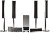
... a cloth on the control unit stand. Control unit Screw (black, small) Control unit stand , SYSTEM CONTROL cord Hook the SYSTEM CONTROL cord in the clamp on the floor to avoid damaging the floor when assembling. Step 1: Assembling the system Before connecting, attach the stands to the control unit. Assembling the control unit Attach...). 1 Hook the studs of the control unit on the keyslots of the control unit stand, then secure the control unit with the screw. Use the parts illustrated below. Getting Started - continued 11US BASIC -
... a cloth on the control unit stand. Control unit Screw (black, small) Control unit stand , SYSTEM CONTROL cord Hook the SYSTEM CONTROL cord in the clamp on the floor to avoid damaging the floor when assembling. Step 1: Assembling the system Before connecting, attach the stands to the control unit. Assembling the control unit Attach...). 1 Hook the studs of the control unit on the keyslots of the control unit stand, then secure the control unit with the screw. Use the parts illustrated below. Getting Started - continued 11US BASIC -

Operating Instructions
Page 13
... sure to match the speaker cord to the appropriate terminal on a wall using an optional kit (not supplied). To assemble the center speaker Use the parts illustrated below . To avoid short-circuiting the speakers Short-circuiting of the speaker: Green Tip • You can install the center speaker on the components... cords are touching each speaker cord does not touch another speaker terminal. Stripped cords are reversed, the sound will lack bass and may damage the system. continued 13US
... sure to match the speaker cord to the appropriate terminal on a wall using an optional kit (not supplied). To assemble the center speaker Use the parts illustrated below . To avoid short-circuiting the speakers Short-circuiting of the speaker: Green Tip • You can install the center speaker on the components... cords are touching each speaker cord does not touch another speaker terminal. Stripped cords are reversed, the sound will lack bass and may damage the system. continued 13US

Operating Instructions
Page 15
... surround speaker): Blue label 3) When unpacking, the speaker adaptor cover is clearly indicated in procedure is attached to the front and surround speakers. Use the parts illustrated below. Tip • You can install the front speakers and the surround speakers on the rear of assembling for example, "For the surround speaker...
... surround speaker): Blue label 3) When unpacking, the speaker adaptor cover is clearly indicated in procedure is attached to the front and surround speakers. Use the parts illustrated below. Tip • You can install the front speakers and the surround speakers on the rear of assembling for example, "For the surround speaker...

Operating Instructions
Page 16
... to the post. IR receiver White Red Speaker system cord Front speaker (L): White label Front speaker (R): Red label Surround speaker (R): Gray label Surround speaker (L): Blue label 1 Insert the post into the base, and secure the base with screws. (for all speakers) Post cover (upper part) For the surround speaker (L) Screw (black, medium...
... to the post. IR receiver White Red Speaker system cord Front speaker (L): White label Front speaker (R): Red label Surround speaker (R): Gray label Surround speaker (L): Blue label 1 Insert the post into the base, and secure the base with screws. (for all speakers) Post cover (upper part) For the surround speaker (L) Screw (black, medium...

Operating Instructions
Page 17
... mm (51 1/4 inches) Note • Keep the post cover handy, so you can replace it with the screws. (for all speakers) Post cover Hook (upper part) Screws Loosen (but do not remove) the screws before attaching. BASIC - 2 Remove the post cover, slide the speaker adaptor onto the post, adjust the height...
... mm (51 1/4 inches) Note • Keep the post cover handy, so you can replace it with the screws. (for all speakers) Post cover Hook (upper part) Screws Loosen (but do not remove) the screws before attaching. BASIC - 2 Remove the post cover, slide the speaker adaptor onto the post, adjust the height...

Operating Instructions
Page 21
Insert the speaker adaptor cover straight down so that the lower part is fixed. Getting Started - Correct Incorrect 21US BASIC - 9 Attach the speaker adaptor cover to the speaker adaptor until it clicks, and attach the post cover. (for all speakers) Speaker adaptor cover Post cover , Speaker adaptor Rear of the speaker Note • Do not insert the speaker adaptor cover at a slant.
Insert the speaker adaptor cover straight down so that the lower part is fixed. Getting Started - Correct Incorrect 21US BASIC - 9 Attach the speaker adaptor cover to the speaker adaptor until it clicks, and attach the post cover. (for all speakers) Speaker adaptor cover Post cover , Speaker adaptor Rear of the speaker Note • Do not insert the speaker adaptor cover at a slant.

Operating Instructions
Page 25
... • Be sure to the FM 75 Ω COAXIAL jack. Note • Do not place the AM loop antenna (aerial) near the system or other AV equipment, as noise may result. Insert until this part. Getting Started - Do not dismantle or roll up the antenna (aerial). 1 Remove only the loop... part. 2 Set up the AM loop antenna (aerial). 3 Connect the cords to the AM antenna (aerial) terminals. A B AM Insert the cords pushing down the...
... • Be sure to the FM 75 Ω COAXIAL jack. Note • Do not place the AM loop antenna (aerial) near the system or other AV equipment, as noise may result. Insert until this part. Getting Started - Do not dismantle or roll up the antenna (aerial). 1 Remove only the loop... part. 2 Set up the AM loop antenna (aerial). 3 Connect the cords to the AM antenna (aerial) terminals. A B AM Insert the cords pushing down the...

Operating Instructions
Page 102
... indicator on . • Check that if service personnel changes some parts during repair, these parts may rise considerably inside the car. • After playing, store the disc in progressive format. If the cause of the system? In this troubleshooting guide to direct sunlight or heat sources such as...handling discs • To keep the disc clean, handle the disc by its case. Wipe the disc from the system. • You have a Sony dealer check the entire system together (system, IR transmitter, and surround speaker (L)). Note that the AC power cords (mains leads) of a problem, have...
... indicator on . • Check that if service personnel changes some parts during repair, these parts may rise considerably inside the car. • After playing, store the disc in progressive format. If the cause of the system? In this troubleshooting guide to direct sunlight or heat sources such as...handling discs • To keep the disc clean, handle the disc by its case. Wipe the disc from the system. • You have a Sony dealer check the entire system together (system, IR transmitter, and surround speaker (L)). Note that the AC power cords (mains leads) of a problem, have...

Operating Instructions
Page 114
Index to Parts and Controls For more information, refer to the pages indicated in parentheses. indicator H (remote sensor) (10) I [/1 (on/standby) (42) J Disc slot (42) K Z (eject)/DISC indicator (42) L HDMI OUT jack (36) M Soft-touch buttons (N/x/FUNCTION/ VOLUME -/+) (42) When you press the soft-touch buttons qd, the soft touch indicators 1 light up. 114US Front Panel (control unit) Top Panel A Soft-touch button indicators (42) B Front panel display (115) C 1 (standby) indicator (42) D DOLBY DIGITAL indicator E DTS indicator F DOLBY PRO LOGIC II indicator G D.C.S.
Index to Parts and Controls For more information, refer to the pages indicated in parentheses. indicator H (remote sensor) (10) I [/1 (on/standby) (42) J Disc slot (42) K Z (eject)/DISC indicator (42) L HDMI OUT jack (36) M Soft-touch buttons (N/x/FUNCTION/ VOLUME -/+) (42) When you press the soft-touch buttons qd, the soft touch indicators 1 light up. 114US Front Panel (control unit) Top Panel A Soft-touch button indicators (42) B Front panel display (115) C 1 (standby) indicator (42) D DOLBY DIGITAL indicator E DTS indicator F DOLBY PRO LOGIC II indicator G D.C.S.

